Table of Contents
Advertisement
Quick Links
RADA VZ1 10 Thermostatic Bar Valve
Installation and User Guide
Installer: This Manual is the property of the customer and must be retained with
the product for maintenance and operational purposes.
Model Name:
Product Code:
Date of Manufacture:
(Your guarantee information is included in this guide. Please keep these details
safe as you will need them when registering your product guarantee.)
IMPORTANT
Affix Sticker Here
1
For SPARES,
ADVICE or REPAIRS
please call us free
on 0344 571 1777
(UK only)
1320703-W2-B
Advertisement
Table of Contents

Related Manuals for Kohler rada VZ1 10


Summary of Contents for Kohler rada VZ1 10
- Page 1 RADA VZ1 10 Thermostatic Bar Valve Installation and User Guide For SPARES, ADVICE or REPAIRS please call us free on 0344 571 1777 (UK only) IMPORTANT Installer: This Manual is the property of the customer and must be retained with the product for maintenance and operational purposes.
-
Page 2: Type 2 Valves
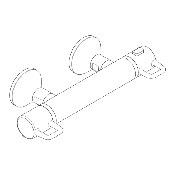
Rada VZ1 10 Chrome HP-S The Rada VZ1 10 is a thermostatic shower valve with a separate control lever for on/off and temperature control. The Rada VZ1 10 incorporates a wax capsule temperature sensing unit which provides an almost immediate response to changes in pressures or temperature of the incoming water supplies to maintain the selected temperature. -
Page 3: Pack Contents
Pack Contents 1 x 6 l/min Flow Regulator 1 x Bar Valve 1 x Component Pack, Containing: 1 x Pair of Handles 1 x Plastic Pipe Guide 2 x Wall Brackets 2 x Olives ... - Page 4 Dimensions COLD 150 mm 135 mm ø 45 mm 70 mm 300 mm 83 mm 1320703-W2-B...
-
Page 5: Recommended Usage
Ensure that any pipework that could become frozen is properly insulated. DO NOT perform any unspecified modifications to the shower or its accessories. When servicing only use genuine Kohler Rada replacement parts. If the shower is dismantled during installation or servicing then, upon completion, an inspection must be made to ensure all connections are tight and that there are no leaks. -
Page 6: Using The Shower
Using the Shower The shower must be operated and maintained in accordance with the requirements of this guide. Make sure you fully understand how to operate the shower before use, read all instructions and retain this guide for future reference. DO NOT switch the shower on if there is a possibility that the water in the shower unit or fittings is frozen. -
Page 7: Specifications
Specifications Pressures Maximum Static Pressure 1000 kPa (10 bar) Maximum Maintained Pressure 500 kPa (5 bar) Minimum Maintained Pressure 100 kPa (1 bar) (Gas Water Heater) (for optimum performance supplies should be nominally equal) Minimum Maintained Pressure 10 kPa (0.1 bar) (Gravity System) (0.1 bar = 1 Metre head from cold tank base to shower handset outlet) -
Page 8: Flow Rates
Flow Rates Typical Flow Rates on Low Pressure System (0.1 bar to 1 bar) Outlet Temperature = 39°C 65/15°C Inlet Temperature with 6 L/min Flow Regulator Pressure loss (bar)* *Note: Pressure Loss = Inlet Pressure - Outlet Pressure (measured at valve outlet) 1320703-W2-B... -
Page 9: Installation
Suitable Plumbing Installations The Thermostatic Mixer can be installed with all systems with balanced pressures. Mixed gravity and mains supplies are not recommended. Installation Warning! This product does not allow for reversed inlets and will deliver unstable temperatures if fitted incorrectly. General Installation of the shower must be carried out in accordance with these instructions by qualified, competent personnel. - Page 10 11. The water supplies to this product should be isolated if the product is not to be used for a long period of time. If the product or pipework is at risk of freezing during this period they should also be drained of water. 12.
- Page 11 Installation of Bar Valve 25 mm 25 mm COLD Plastic Pipe Guide Fit the plastic pipe guide over the inlet Note: Connections are; Hot-Left, pipes. Level the pipe guide and secure Cold- Right. to the wall to hold in position. Leave the guide in place and finish the wall.
- Page 12 Install the olives and the connectors. Tighten finger tight and then another 1/4 to 1/2 turn. Turn on the water supply and flush the pipework. Note: Supplied olives must be used. Ensure pipe manufacturer’s instructions are followed (i.e. use pipe inserts for plastic pipe). Attach the bar valve to the wall fixings.
- Page 13 Mixing Valve Install the shower fittings, refer to the Installation Guide packed with the product. Flow Regulator Check for leaks on all connections Washer Shower Hose you have made. A 6 l/min flow regulator can be fitted into the outlet. Note: Orientate flow regulator as shown above.
- Page 14 5. Remove the fixing screw holding on the handle attachment components using a 3 mm Allen key. Remove the two attachment components. 6. Temperature adjuster can be moved 3 positions in either direction, one position equals 1˚C. Rotate adjuster anti-clockwise to increase temperature and rotate clockwise to decrease temperature.
-
Page 15: Operation
Operation Temperature Decrease Override Button Temperature Increase Temperature Temperature Handle Adjusting the Temperature The temperature is controlled by rotating the temperature handle. For safety reasons, the temperature is limited by an override stop. To obtain a higher temperature, press the override button on the temperature handle and continue to rotate the handle. Adjusting the Flow The flow is controlled by rotating the flow handle. -
Page 16: Fault Diagnosis
Fault Diagnosis If you require a Rada trained service engineer or agent, refer to ‘Customer Service’. Symptom Cause / R ectification Water too hot or too cold Inlets reversed (hot supply to cold supply).Rework inlet pipework. Check filters for any blockage. Check the maximum temperature setting (If you have a combination type boiler it may not be producing sufficient hot water at the desired flow rate). -
Page 17: Spare Parts
Spare Parts 1836.179 Fixing Kit 1836.174 Inlet Seal / Filter 1900.069 Handle Attachment Pack 1900.070 Concealing Plates 1900.051 Single Outlet Valve 1900.077 Flow Regulator Kit (2 x 6 L/min) (Not Illustrated) 1900.069 Handle Attachment Pack 1 x Pair of Handles 1900.068 1320703-W2-B... - Page 18 Notes 1320703-W2-B...
- Page 19 Notes 1320703-W2-B...
-
Page 20: Customer Services Guarantee
Kohler Mira Limited. Cromwell Road, K/E S.A.S. Cheltenham, 3 rue de Brennus, The company reserves the right Gloucestershire 93631, La Plaine Saint-Denis, to alter product specifi cations GL52 5EP France without notice. 14648 1473740-W6-A 1320703-W2-B © Kohler Mira Limited, January 2022...
Need help?
Do you have a question about the rada VZ1 10 and is the answer not in the manual?
Questions and answers