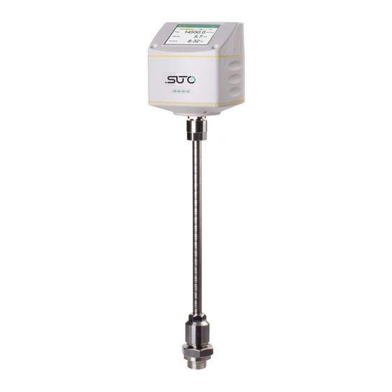
SUTO S430 Instruction And Operation Manual
Pitot tube flow sensor
Hide thumbs
Also See for S430:
- Instruction and operation manual (52 pages) ,
- Instruction and operation manual (32 pages) ,
- Instruction and operation manual (52 pages)
Table of Contents
Advertisement
Quick Links
Advertisement
Table of Contents

Related Manuals for SUTO S430


Summary of Contents for SUTO S430
- Page 1 English Instruction and operation manual S430 Pitot tube flow sensor...
- Page 2 The device is destined exclusively for the described application. SUTO offers no guarantee for the suitability for any other purpose. SUTO is also not liable for consequential damage resulting from the delivery, capability or use of this device.
-
Page 3: Table Of Contents
7.3 Configuration using the optional sensor display......26 7.3.1 Starting process................26 7.3.2 About the home page...............26 7.3.3 Configuration instructions..............27 8. Sensor signal outputs..............28 8.1 Analog output..............28 8.2 Pulse output.................28 8.3 Pulse Connection Diagram............30 8.4 Modbus output ..............30 8.5 M-Bus output ..............31 S430... - Page 4 9. Calibration................32 10. Maintenance................32 11. Disposal or waste..............32 12. Warranty................32 Appendix..................34 S430...
-
Page 5: Safety Instructions
• Consider all regulations for electrical installations. • The system must be disconnected from any power supply during maintenance work. • Any electrical work on the system is only allowed by authorized qualified personal. S430... - Page 6 • Always observe the direction of the flow when installing the sensor. The direction is indicated on the housing. • Do not exceed the maximum operation temperature at the sensors tip. • Avoid condensation on the sensor element as this will affect the accuracy enormously. S430...
-
Page 7: Application
, pressure in bar, temperature in °C. Other units can be programmed by the optional display or the service kit. The S430 flow sensor is not developed to be used in explosive areas. For the use in explosive areas please contact the manufacturer. -
Page 8: Features
• Tube diameters from 1” up to 10”, larger diameters on request. • No mechanical wear parts. • All parts which are in contact with the medium are made of stainless steel. • Optional display directly on the sensor, showing velocity, volume flow and consumption, temperature, pressure. S430... -
Page 9: Technical Data
Protection class IP65 Dimensions See dimensional drawing on chapter 5 Display (optional) 2.4” colour graphics display with keypad (optional) Tube diameter 1” to 10” (bigger diameters on request) Screwing thread G1/2” (ISO 228/1) Weight 1.10 kg S430... -
Page 10: Electrical Data
Ambient/process humidity <90% Process pressure at 0.6 MPa Working range: Flow range for air at 6 barg, 50°C and 90% humidity. For other gas and condition please see appendix or download flow range software from the homepage of the manufacturer. S430... - Page 11 4. Technical Data Cut-off flow of S430 is pressure depending. Following chart shows the relationship at tube of 100 mm, 50°C and 90% humidity. For other tube and conditions please download “Flow range” software from the homepage of the manufacturer.
-
Page 12: Dimensional Drawing
5. Dimensional drawing 5. Dimensional drawing S430... -
Page 13: Installation
6. Installation 6. Installation Before you install the sensor, make sure that all components listed below are included in your package. Qty Description Item No. S430 Sensor S695 4300/S695 4302 Sealing ring No P/N Alignment key No P/N M12 plug... -
Page 14: Inlet And Outlet Sections
L1 : Length of inlet section L2 : Length of outlet section D : Diameter of tube Please keep at least 8 x D upstream and 3 x D downstream to ensure an significant influence to the measuerement due to up and downstreampipe bends. S430... -
Page 15: Insertion Angles
Installation in a vertical pipe is possible, required the flow is from bottom up and the sensor has at least a 10 degree angle (recommended is 20 degree). ATTENTION: Do not install in vertical pipes if the flow is from top to down. S430... -
Page 16: Calculating The Insertion Depth
Centre installation is the default and recommended installation type. Insertion depth= x+ y ; OD=Outer diameter of pipe Example for a 2” pipe and a 87 mm ball valve: y=87 mm ; OD=60.3 mm 60.3 mm =30.15 mm Insertion depth=30.15 mm+ 87 mm=117.15 mm S430... -
Page 17: Non-Centre Installation
Insertion depth= x+ y+ 100 x is the wall thickness of pipes Example for a 12” pipe, the wall thickness of pipes 9 mm and a 87 mm ball valve: x=9 mm ; y=87 mm Insertion depth=9 mm+ 87 mm+ 100 mm=196 mm S430... -
Page 18: Installation Of The Sensor
10. Tighten clamp sleeve with clamping torque 20...30 Nm. 11. During the final check control the installation depth again because sometimes the shaft is moved from its original position due the compressed air. S430... -
Page 19: Performing The Zero Flow Calibration
1. On your mobile device, download the S4C-FS App from the SUPPORT > Downloads menu on https://suto-itec.com or from Google Play store as needed. 2. Turn on Bluetooth on your mobile device. 3. Launch the S4C-FS App. S430... - Page 20 Note: Only through scanning the QR code can you edit system settings and perform calibrations. 5. Click the System icon. On the System screen that appears, click Calibration and follow the onscreen instructions to perform the zero flow calibration. S430...
-
Page 21: Using The Local Display
1. Hold the flow sensor firmly. 2. Release the clamp sleeve from the connection head very slowly while keeping your hand on the top of the sensor head. 3. Pull out the shaft slowly until the sensor is fully returned into the value. S430... -
Page 22: Making Electrical Connection
Connection pins connector plug M12 Connection pins (view from the clamping side) Pin assignment connector plug M12 Output Version Connector Pin 1 Pin 2 Pin 3 Pin 4 Pin 5 Modbus Pulse and analog M-Bus Wire colour brown white blue black grey S430... -
Page 23: Configuration
App S4C-FS, local display (optional), or service kit (optional). Note: You can also use these tools to view parameter values and error messages. 7.1 Description of sensor settings Settings provided on S430 come into the following categories. 7.1.1 Flow settings Parameter Description Pipe diameter Enter the pipe diameter in the unit of mm. -
Page 24: Unit Settings
7.1.4 Factory settings Configure filter grade at the scale of 0 to 127. 7.1.5 Output settings Configure output settings for Modbus such as the device address, Baud rate, Parity, and Stop bit 7.1.6 Language setting Select the UI language. S430... -
Page 25: Configuration Using The Service App S4C-Fs
App from the Google Play store or our Website. To change settings using the App, you must scan the QR code on the calibration certificate. This ensures that only valid users can change the sensor settings. For more detailed instructions, refer to steps described on page 20. S430... -
Page 26: Configuration Using The Optional Sensor Display
Now the display goes to the standard mode, showing the online values, flow, velocity and pressure, alternately. 7.3.2 About the home page Home page: • Status bar • Moving bar to indicate flow and cut-off value • Measuring values S430... -
Page 27: Configuration Instructions
3. Use the Up and Down keys to choose the parameter that you want to change. 4. Use the Up and Down keys to select desired entry box or adjust the values. 5. Press the Enter key to confirm the changes. S430... -
Page 28: Sensor Signal Outputs
The sensor will send out one pulse per consumption unit. This pulse output can be connected to an external pulse counter to count the total consumption. The number of m per second are summed up and indicated after one second. Pulse length depends on consumption rate. S430... - Page 29 In case the flow rate is higher than 50 m /s, l/s of ft /s, the S430 can not output the pulses with default settings (one pulse per consumption unit). For this the pulse can be set by our service software or a connected display to 1 pulse per 10 consumption units or 1 pulse per 100 consumption units.
-
Page 30: Pulse Connection Diagram
Device address Framing / parity / stop bit : 8, E, 1 Response time : 1 second Response delay : 0 ms Inter-frame spacing : 7 char Remarks • Modbus communication settings can be changed by the service software. S430... -
Page 31: M-Bus Output
Fabrication No. Baud rate / parity : 2400 bps / even Device address : primary address: 1; secondary address: serial number Response delay / : 7ms / 500ms timeout Channel Data information Field Unit Range coding (DIF) Counter Flow S430... - Page 32 Please contact the manufacturer for details. 12. Warranty SUTO provides a warranty for this product of 24 months covering the material and workmanship under the stated operating conditions from the date of delivery. Please report any findings immediately and within the warranty time.
- Page 33 • If the serial number has been changed, damaged or removed. Other claims, especially those for damage occurring outside the instrument are not included unless responsibility is legally binding. Warranty repairs do not extend the period of warranty. ATTENTION! Batteries have a reduced warranty time of 12 month. S430...
- Page 34 0.840 700.00 232754.32 3879.24 3879238.6 64653.98 136994.1 276458.4 4607.64 76.79 0.840 800.00 304005.64 5066.76 5066760.6 84446.01 178931.0 361088.5 6018.14 100.30 0.840 900.00 384757.14 6412.62 6412618.9 106876.98 226459.6 457002.6 7616.71 126.95 0.840 1000.00 475008.81 7916.81 7916813.5 131946.89 279579.7 564200.8 9403.35 156.72 S430...
- Page 35 S430...
- Page 36 FCC Statement: This device complies with part 15 of the FCC rules Operation is subject to the following two conditions: (1) this device may not cause harmful interference, and (2) this device must accept any interference received, including interference that may cause undesired operation. NOTE: The manufacturer is not responsible for any radio or TV interference caused by unauthorized modifications to this equipment.
- Page 37 SUTO iTEC GmbH SUTO iTEC (ASIA) Co., Ltd. Werkstr. 2 Room 10, 6/F, Block B, Cambridge Plaza 79426 Buggingen 188 San Wan Road, Sheung Shui, N.T. Germany Hong Kong Tel: +49 (0) 7631 936889-0 Tel: +852 2328 9782 Fax: +49 (0) 7631 936889-19...
Need help?
Do you have a question about the S430 and is the answer not in the manual?
Questions and answers