
Related Manuals for SUTO S431 OEM


Summary of Contents for SUTO S431 OEM
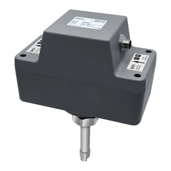
- Page 1 English Instruction and Operation Manual S431 OEM Pitot Tube Compressor Flow Meter (Inline)
- Page 2 The device is designed exclusively for the described application. SUTO offers no guarantee for suitability for any other purpose. SUTO is also not liable for consequential damage that results from the delivery, capability, or use of this device.
-
Page 3: Table Of Contents
9.2 Using Service App S4C-FS............22 9.2.1 Flow Settings..............23 9.2.2 Unit Settings...............24 9.2.3 Calibration..............25 9.2.4 Uploading Settings............26 9.2.5 Downloading Settings..........26 10 Signal outputs.................27 10.1 Analog output..............27 10.2 Pulse output..............27 10.2.1 Pulse connection diagram...........29 10.3 Modbus output ..............30 11 Maintenance................32 12 Disposal or waste..............32 S431 OEM... -
Page 4: Safety Instructions
• Consider all regulations for electrical installations. • The system must be disconnected from any power supply during maintenance work. • Any electrical work on the system is only allowed by authorized qualified personal. S431 OEM... - Page 5 • Always observe the direction of the flow when installing the sensor. The flow direction is indicated on the housing. • Do not exceed the maximum operating temperature at the sensor tip. • Avoid condensation on the sensor element because it will affect the accuracy enormously. S431 OEM...
-
Page 6: Registered Trademarks
• Avoid direct UV and solar radiation during storage. • For the storage, the humidity must be <95% with no condensation. 2 Registered trademarks Trademark Trademark owner SUTO ® SUTO iTEC MODBUS ® Modbus Organization, Hopkinton, USA Android™, Google LLC Google Play S431 OEM... -
Page 7: Rf Exposure Information And Statement
• Consult the dealer or an experienced radio/TV technician for help 。 • This device and its antenna(s) must not be co-located or operating in conjunction with any other antenna or transmitter. S431 OEM... -
Page 8: Application
4 Application 4 Application The S431 OEM Pitot Tube Compressor Flow Meter (Inline) is designed to measure the air delivery of a compressor. It can be installed at the discharge side inside the compressor where wet and contaminated air occurs. -
Page 9: Technical Data
0 ... 16 bar(g) Sensor Piezzo resistive sensor Temperature Accuracy 0.5 °C Selectable units °C, °F Measuring range -40 ... +230 °C Sensor Pt1000 Reference conditions Selectable conditions 20 °C 1000 mbar (ISO1217) 0 °C 1013 mbar (DIN1343) freely adjustable S431 OEM... -
Page 10: Signal / Interface And Supply
CE, RoHS, FCC Process connection M32 x 1.5 mm, with SW36 wrench to fasten the Weight 1.4 kg Operating conditions Medium Wet/dry air, other gases Medium quality Non corrosive Medium temperature -20 ... +120 °C Medium humidity No requirements S431 OEM... - Page 11 Ambient humidity <95 % rH Storage temperature -30 ... 70 °C Transport temperature -10 ... 70 °C Pipe sizes >=DN50 * The specified accuracy is valid only within the minimum and maximum flows that are indicated in section 6.4. S431 OEM...
-
Page 12: Flow Ranges
The exact range can be calculated using Flow Range software, which can be downloaded from www.suto-itec.com. • To fast access the tool download page, enter "flowrange" (without spaces) in the search field, and then click the search result. -
Page 13: Dimensional Drawing
7 Dimensional drawing 7 Dimensional drawing S431 OEM... -
Page 14: Installation
Before you install the sensor, make sure that all components listed below are included in your package. Qty Description Order No. S431 OEM Pitot Tube Horizontal pipes: S695 4310 Compressor Flow Meter (Inline) Option reverse flow direction: A4319 Vertical pipes: S695 4311... - Page 15 • The sensor is for indoor use only! At an outdoor installation, the sensor must be protected from solar radiation and rain. Remark: If there is any combination of the following situations, the longest straight inlet section must be maintained. Expansion Reduction 90° Bend 2×90° Bend S431 OEM...
-
Page 16: Welding Nipple And Welding Fixture
Welding nipple DN50 ... DN80 for horizontal pipes installation A4310 A4311 Welding nipple DN100 ... DN900 for horizontal pipes installation A4312 Welding nipple DN50 ... DN80 for vertical pipes installation A4313 Welding nipple DN100 ... DN900 for vertical pipes installation S431 OEM... - Page 17 8 Installation Horizontal pipe installation - S695 4310 S4695 4310 horizontal pipe installation Horizontal pipe installation - A4319 A4319 Horizontal pipe installation Valid installation angle from 20 ... 90º option S431 OEM...
- Page 18 Vertical pipe installation - S695 4311 In addition, you also can use the customized welding fixture for welding processing to get the best positioning and welding quality, as shown below. fixture fixture Welding in a horizontal pipe Welding in a vertical pipe S431 OEM...
-
Page 19: Removing The Sensor
Follow the steps below to re-install the sensor after maintenance: 1. Place the O-ring into the recess of the connection nut. 2. Insert the sensor back to the pipe. 3. Tighten the connection nut. S431 OEM... -
Page 20: Performing The Electrical Connection
Positive 4 … 20 mA signal (isolated) isolated Negative 4 ... 20 mA signal (isolated) isolated Isolated pulse output (switch) Modbus/RTU data + Modbus/RTU data - Not applicable ATTENTION! Do not screw the M12 connector using force. Otherwise it might damage the connection pins. S431 OEM... -
Page 21: Configuration
Service App S4C-FS. Search and installation of the S4C-FS are as follows: 1. On your Android device, download the S4C-FS app from Google Play Store or from the SUTO website. 2. Install S4C-FS. 9.1 Registering Before using the S4C-FS App, you must register. -
Page 22: Using Service App S4C-Fs
Scan QR Code: In the System menu select Scan QR Code. After scanning the QR code signal icon changes from Orange to Green. After finishing this step you can return to the online screen and see online values. S431 OEM... -
Page 23: Flow Settings
Sensor installation depth You have to select the insertion depth of either 25 mm (DN50 … DN80) or 50 mm (>DN100). Cut-Off velocity Select between 20 or 10 m/s (standard velocity). The velocity values below this setting appear as zero. S431 OEM... -
Page 24: Unit Settings
9 Configuration 9.2.2 Unit Settings Select the desired physical unit for the different measurement channels. S431 OEM... -
Page 25: Calibration
Since the compressor specific settings have been stored in a cloud database, the operator can download the settings of the replaced sensor into the replacement sensor through the mobile app. The replaced sensor can be return to a SUTO service facility for re- calibration and maintenance. S431 OEM... -
Page 26: Uploading Settings
User will be asked to enter the serial number of the previous S431. In case the settings can be found on the cloud server it will be downloaded into the new sensor unit. S431 OEM... -
Page 27: Signal Outputs
The S431 sends out one pulse per a consumption unit by default. This pulse output can be connected to an external pulse counter to count the total consumption. The number of m per second are accumulated and indicated after one second. The pulse length depends on consumption rate. S431 OEM... - Page 28 For example, with the setting of 1 pulse per 10 m , the S431 sends one pulse each 10 m Example: Volume flow Pulse length Max. consumption [ms] 10,800 ≦ 10,800 > 10,800 28,800 > 28,800 57,600 S431 OEM...
-
Page 29: Pulse Connection Diagram
10 Signal outputs 10.2.1 Pulse connection diagram Using the isolated pulse switch (M12 connector: Pin4 and Pin5) Variant 1: Variant 2: S431 OEM... -
Page 30: Modbus Output
• Byte order (32-bit data): MID-LITTLE-ENDIAN. • To properly decode the 4-byte float and unsigned integer data in the response message, the master must change the byte order from the MID-LITTLE-ENDIAN received to the order that it is using (LITTLE-ENDIAN or BIG-ENDIAN). S431 OEM... - Page 31 Bit Description Description Measurement over range Pressure sensor broken Temperature over range Temperature sensor broken Pressure over range NTC broken Pulse over range Flow direction 0: standard 1: reversed Calibration overdue BT module connected Differential pressure sensor broken S431 OEM...
-
Page 32: Maintenance
The device, the accessories and its packings must be disposed according to your local statutory requirements. The dispose can also be carried by the manufacturer of the product. Please contact the manufacturer for details. S431 OEM... - Page 33 SUTO iTEC GmbH SUTO iTEC (ASIA) Co., Ltd. Grißheimer Weg 21 Room 10, 6/F, Block B, Cambridge Plaza D-79423 Heitersheim 188 San Wan Road, Sheung Shui, N.T. Germany Hong Kong Tel: +49 (0) 7634 50488 00 Tel: +852 2328 9782...
Need help?
Do you have a question about the S431 OEM and is the answer not in the manual?
Questions and answers