Table of Contents
Advertisement
Quick Links
®
™
EMC
VNX
Family
™
VNX7500
Hardware Information Guide
REV A03
October, 2011
This guide describes one of five models available in the VNX Series, the EMC
VNX7500™. This document provides an overview of the architecture, components, and
features of the VNX7500. The specific aspects of the Block and File (Unified) VNX7500
platform hardware and its major components include the front and rear connectors and
LED indicators on the storage processor enclosure (SPE), the 1U and 2U standby power
supply (SPS), the Control Station, the Data Mover enclosure, and the 2U, 25 (2.5-inch), the
3U, 15 (3.5-inch), or the 4U, 60 (2.5-inch or 3.5-inch) disk drive disk-array enclosure
(DAE).
This guide is available online at https://mydocs.emc.com/VNX/. Go to the About VNX
section, and then select Learn about VNX. Next, follow the steps in the wizard.
Topics include:
Product software and hardware release revisions ...................................................... 4
◆
Revision history ........................................................................................................ 4
◆
Where to get help...................................................................................................... 4
◆
How this document is organized ............................................................................... 5
◆
Related documentation............................................................................................. 5
◆
Overview................................................................................................................... 6
◆
VNX7500 Block and File product description ............................................................. 8
◆
System component description ............................................................................... 17
◆
I/O modules............................................................................................................ 45
◆
Disk-array enclosure (DAE) ...................................................................................... 63
◆
Cabling ................................................................................................................... 95
◆
VNX7500 DAE cabling ............................................................................................. 96
◆
®
Advertisement
Table of Contents

Subscribe to Our Youtube Channel
Related Manuals for EMC2 VNX VNX7500


Summary of Contents for EMC2 VNX VNX7500
-
Page 1: Table Of Contents
® ™ Family ™ VNX7500 Hardware Information Guide REV A03 October, 2011 ® This guide describes one of five models available in the VNX Series, the EMC VNX7500™. This document provides an overview of the architecture, components, and features of the VNX7500. The specific aspects of the Block and File (Unified) VNX7500 platform hardware and its major components include the front and rear connectors and LED indicators on the storage processor enclosure (SPE), the 1U and 2U standby power supply (SPS), the Control Station, the Data Mover enclosure, and the 2U, 25 (2.5-inch), the... -
Page 2: Product Software And Hardware Release Revisions
Product software and hardware release revisions Product software and hardware release revisions As part of an effort to improve its product lines, EMC periodically releases revisions of its software and hardware. Therefore, some functions described in this document might not be supported by all versions of the software or hardware currently in use. -
Page 3: How This Document Is Organized
How this document is organized How this document is organized The major sections of this guide are listed in the following table. Title Description “Overview” on page 6 Describes the software and hardware features of a typical VNX7500 along with a front view example of the VNX7500. “VNX7500 Block and File Describes and shows the front and rear views of a typical product description”... -
Page 4: Overview
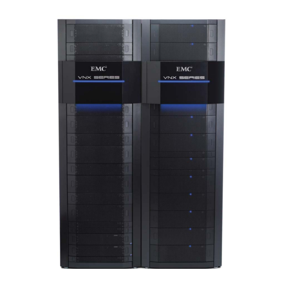
Overview For installation, adding, or replacing tasks, go to the VNX tasks section, and then ◆ select the appropriate heading. For example, to download a PDF copy of the VNX7500 Block Installation Guide , go to Install VNX and follow the steps in the wizard. For server-related tasks, go to the Server tasks for the VNX5300, VNX5500, VNX5700, ◆... - Page 5 Overview Unified replication with RecoverPoint support for both file and block data ◆ ™ Updated unified management with Unisphere now delivering a more cohesive ◆ unified user experience VNX-000597 Figure 1 Example of a VNX7500 platform with front bezel EMC VNX7500 Hardware Information Guide...
-
Page 6: Vnx7500 Block And File Product Description
VNX7500 Block and File product description VNX7500 Block and File product description This section shows an example of the front and rear views of a Block and File (Unified) VNX7500 platform. Note: A fully configured Block and File (Unified) VNX7500 platform includes up to sixty-six 3U DAEs (a maximum of 990 3.5-inch disk drives), or up to forty 2U DAEs (a maximum of 1000 2.5-inch disk drives), up to fifteen 4U DAEs and one 3U DAE (a maximum of 915... - Page 7 VNX7500 Block and File product description Note: Figure 2 on page 8 shows only the VNX7500 platform components. The DAEs are not shown. Note: The configuration in Figure 2 on page 8 is primarily used with the 3U or 2U DAEs only.
- Page 8 VNX7500 Block and File product description Note: Figure 3 on page 9 shows only the VNX7500 platform components. The DAEs are not shown. IMPORTANT The 6-Gb/s SAS I/O module is always located in slot 0 of SP A and SP B.) Note: In the example storage processor enclosure in Figure 3 on page 9, the first FC I/O...
- Page 9 VNX7500 Block and File product description IMPORTANT A dual 2U SPS is used when a 4U DAE with Flash drives is used in a Vault drive configuration. Otherwise, the dual 1U SPS is used with the 3U DAE as the Vault drive. Note: Figure 4 on page 10 shows only the VNX7500 platform components.
- Page 10 VNX7500 Block and File product description IMPORTANT A dual 2U SPS is used when a 4U DAE with Flash drives is used in a Vault drive in a 40U Dense rack. Otherwise, the dual 1U SPS is used with the 3U DAE as the Vault drive. Note: Figure 5 on page 11 shows only the VNX7500 platform components.
- Page 11 VNX7500 Block and File product description Table 1 VNX7500 hardware feature quick reference File Block Config. System Config. Minimum Maximum I/O slots memory System form # of Drive per Data Data per Data slots memory factor drives types Mover Movers Mover Protocols per SP...
- Page 12 VNX7500 Block and File product description • A CPU module with an Intel Xeon 4-core 2.8-GHz processor with six Double Data Rate Three (DDR3) synchronous dynamic RAM (SDRAM) slots supporting 2-, 4-, and 8-GB SDRAM • Five PCI Gen 2 x4 I/O module slots supporting a combination of the following four UltraFlex I/O modules: –...
- Page 13 VNX7500 Block and File product description cm x 48.05 cm x 71.12 cm). Between the front and rear enclosure, a midplane distributes power and signals to all the enclosure components. The CPU modules and the power supply/cooling (fan) modules plug directly into the midplane connections. Note: The previously mentioned dimensions are approximate and do not include the cabinet enclosure and any DAEs.
- Page 14 VNX7500 Block and File product description Two-port 10-Gb/s optical or active Twinax (iSCSI protocol) Two-port 10-Gb/s optical or active Twinax Fibre Channel over Ethernet (FCoE) Four-port 1-Gb/s copper iSCSI One to four Data Mover enclosures with the first Data Mover enclosure having two ◆...
-
Page 15: System Component Description
System component description In a Block and File (Unified) environment, expansion of up to thirteen 4U, 60 (2.5- or ◆ 3.5-inch) disk drive DAEs and three 3U, 15 (3.5-inch) disk drive DAEs (a maximum of 825 drives) is supported Any required cables including LAN cables, modem cables, and serial DB-9 cable. ◆... - Page 16 System component description Note: Figure 6 is a graphical representation of the Block and File (Unified) VNX7500 platform SPE with four power supply/cooling (fan) modules and two CPU modules installed. Table 3 Storage processor enclosure LEDs Color State Description Power Blue Storage processor enclosure is powered up, operating normally...
- Page 17 System component description Table 4 CPU LEDs (continued) Color State Description Fault Amber Storage processor has faulted. Blinking Storage processor goes through six stages of power up: 1. Executes a BIOS check, blinking once every 4 seconds 2. Executes a POST check, blinking once every second 3.
- Page 18 System component description DME front view The front of the Block and File (Unified) VNX7500 platform Data Mover enclosure contains two enclosure status (power and fault) LEDs, as shown in Figure Table 6 on page 20 describes the Data Mover enclosure power and fault LEDs. Note: Figure 9 is a graphical representation of the Block and File (Unified) VNX7500...
- Page 19 System component description CPU LEDs The CPU modules in the Data Mover enclosure contain the power, fault, and unsafe-to-remove LEDs. Figure 10 shows the CPU LEDs and Table 7 describes them. CPU fault LED CPU power LED CPU unsafe to remove LED CNS-001669 Figure 10 CPU LEDs...
- Page 20 System component description Power supply/cooling (fan) module LED The power supply/cooling (fan) modules have status LED on the front. Figure 11 shows the LEDs for the power supply/cooling (fan) modules and Table 8 describes them. Power supply/ cooling (fan) power/fault LED CNS-001673 Figure 11 Power supply/cooling (fan) module LED Table 8 Power supply/cooling (fan) module LED...
- Page 21 System component description CNS-001740 DVD-ROM drive USB 2.0 connector (not used) Control Station switch and status LEDs (for a closer view, see Figure 13 on page Figure 12 VNX7500 platform Control Station (front view) Control Station switch and LEDs Figure 13 shows the location of the Block and File (Unified) VNX7500 platform Control Station switch and LEDs on the front panel.
- Page 22 System component description Table 9 Control Station switch Switch Description Power push-button Toggles the Control Station (location 1) power (push in and hold for about 10 seconds) Table 10 Control Station LEDs Color State Description System status/boot Green Power on/system loaded and (location 2) ready Blinking...
- Page 23 System component description VNX7500 rear view On the rear, viewing from top to bottom, a Block and File (Unified) VNX7500 platform includes the following hardware components: One to two Control Stations ◆ One to four Data Mover enclosures with two to eight Data Movers ◆...
- Page 24 System component description When power returns, the SPS starts recharging the DC battery pack. It might reach a state of full charge relatively quickly. If power remains off for a long period—days or weeks—the DC battery might require more time to charge fully. The storage processor will not use the write cache unless it detects at least one fully charged SPS.
- Page 25 System component description Looking from left to right, Figure 14 shows an example of the rear view of two SPSs (B and A, respectively). 900-XXX-0014 0082 900-XXX-0014 0082 SPS B (optional) SPS A VNX-000282 SPS B AC power in (recessed plug) Power out socket to LCC A on the 1st DAE (ID 2) Power out socket to LCC B on the 1st DAE...
- Page 26 System component description Table 11 describes the LEDs located on each 1U SPS (A and B). Table 11 1U SPS LEDs Color State Description SPS power Green SPS ready and operating normally; battery fully charged Blinking On/battery charging — Off/disconnected SPS battery Amber AC line power is no longer available and the SPS is...
- Page 27 System component description VNX-000290 Figure 16 1U SPS RJ-12 port Table 12 lists the 1U SPS (RJ-12) pin signals used on the connector. Table 12 1U SPS (RJ-12) port and connector pinout RJ-45 pin Signal Description RTS/DSR Ready to send Data transmit ready Shield Shield...
- Page 28 System component description SPS A SPS B VNX-000624 SPS B AC power in (recessed plug) SPS A to SP A management (RJ-12) connector SPS B power out socket to LCC B on the 1st SPS A power on/off toggle switch DAE (ID 2) SPS B power out socket to the SP B power Four SPS A status LEDs (green and amber)
- Page 29 System component description Table 13 describes the rear panel 2U SPS LEDs. Table 13 2U SPS LEDs description Color State Description SPS power Green SPS ready and operating normally; battery fully charged Blinking On/battery charging — Off/disconnected SPS battery Amber AC line power is no longer available and the SPS is supplying DC output power from the battery.
- Page 30 System component description VNX-000626 Figure 20 2U SPS RJ-12 port Table 14 lists the 2U SPS (RJ-12) pin signals used on the connector. Table 14 2U SPS (RJ-12) port and connector pinout RJ-45 pin Signal Description RTS/DSR Ready to send Data transmit ready Shield Shield...
- Page 31 System component description SPE rear view Figure 22 shows an example of an SPE with two SPs (A and B) and the location of the major hardware components that make up these SPs. VNX-000601 Storage processor enclosure Four-port 6-Gb/s SAS I/O module (default) Four-port 8-Gb/s (4-Gb/s) FC I/O module SP management module...
- Page 32 System component description SP management module The SP management module provides the management connections via one 10/100/1000 Ethernet (RJ-45) port. Another RJ-45 port is available to support a service laptop connection. The SP management module includes two RS-232/EIA 232 (DB-9) serial socket connectors (one for service laptop connection and the other for SPS connection) and several LEDs (Figure...
- Page 33 System component description SP management module LEDs Figure 24 shows the LEDs and Table 15 describes them. Power/Fault LED Management port (Activity LED) Management port (Link LED) Service laptop port (Link LED) Service laptop port (Activity LED) VNX-000584 Figure 24 SP management module LEDs Table 15 SP management module LEDs Color State...
- Page 34 System component description Pin 1 Pin 1 VNX-000582 Figure 25 SP management module serial console (DB-9) socket connectors Table 16 lists the SP management module Ethernet (DB-9) pin signals used on the connectors. Table 16 SP management module (DB-9) socket connector pinout DB-9 Pin Signal Description...
- Page 35 System component description DME rear view The rear of the Block and File (Unified) VNX7500 platform DME does not contain any LEDs (Figure 27). Only the Data Mover management module and the I/O modules have LEDs. Note: Figure 27 is a graphical representation of the Block and File (Unified) VNX7500 platform DME rear view with two Data Movers (each Data Mover shows one management module, one four-port 8-Gb/s FC I/O module, and four filler panel modules).
- Page 36 System component description CNS-001754 Power/fault LED DB-9 serial console socket connector Data Mover management module push RJ-45 Ethernet port (labeled 0) button latch handle RJ-45 Ethernet port (labeled 1) RJ-45 Ethernet port (labeled 2) Data Mover enclosure ID numeric display Figure 28 Data Mover management module Data Mover management module Ethernet (RJ-45) ports The Block and File (Unified) VNX7500 platform Data Mover management module comes...
- Page 37 System component description Data Mover management module LEDs Figure 29 shows the LEDs and Table 17 describes them. Power/Fault LED Port 2 (Activity LED) Port 1 (Activity LED) Port 2 (Link LED) Port 1 (Link LED) Port 0 (Link LED) Port 0 (Activity LED) Numeric display (blade enclosure ID)
- Page 38 System component description Pin 1 CNS-001753 Figure 30 Data Mover management module serial console (DB-9) socket connector Table 18 lists the Data Mover management module Ethernet (DB-9) pin signals used on the connector. Table 18 Data Mover management module (DB-9) socket connector pinout DB-9 Pin Signal Description...
- Page 39 System component description Figure 31 shows the orientation of these components. MGMT CNS-001741 AC power in connector DB-9 serial console plug connector PS/2 connector (mouse)—not used Two USB 2.0 connectors (not used) DB-9 serial modem plug connector RJ-45 Ethernet port (labeled A) RJ-45 Ethernet port (labeled CS POST diagnostic LEDs RJ-45 Ethernet port (labeled B)
- Page 40 System component description provide an interface for connecting to 10-, 100-, or 1000-Mb/s networks and provide full-duplex (FDX) capability, which enables simultaneous transmission and reception of data on the Ethernet local-area network (LAN). To access the Ethernet ports, connect a Category 3, 4, 5, 5E, or 6 unshielded twisted-pair (UTP) cable to the RJ-45 connectors on the back of the Control Station, as described in Table Table 19 Ethernet cabling guidelines...
- Page 41 System component description Control Station Ethernet (RJ-45) port LEDs The Control Station (RJ-45) has two LEDs—a green LED to the left of the connector and a bi-color (green/amber) LED to the right of the connector—that indicates the link/activity and speed of the Control Station (RJ-45) ports, respectively (Figure 33).
- Page 42 System component description Control Station serial console (DB-9) plug connector The back of the Block and File (Unified) VNX7500 platform system Control Station includes a standard serial console Electronics Industries Association (EIA) RS-232 interface (DB-9) plug connector (labeled with a wrench tool icon on the right). Notice the orientation of the pins (Figure 35).
-
Page 43: I/O Modules
I/O modules Table 23 lists the Control Station Ethernet (DB-9) pin signals used on the connector. Table 23 Control Station modem (DB-9) plug connector pinout DB-9 Pin Signal Description Carrier detect Received data Transmitted data Data terminal ready Ground Data set ready Clear to send Request to send Ring indicator (not used) - Page 44 I/O modules Four-port 8-Gb/s FC I/O module The four-port 8-Gb/s FC I/O module comes with four optical (fibre) ports, one power/fault LED, and a link/activity LED for each optical port (Figure 37). CNS-001752 Push button latch handle SFP+ (optical) port (four) Power/fault LED SFP+ link/activity LED Figure 37 Four-port 8-Gb/s FC I/O module...
- Page 45 I/O modules Four-port 8-Gb/s FC I/O module LEDs The four-port 8-Gb/s Fibre Channel (FC) I/O module has two different types of status LEDs. Figure 38 shows the LEDs and Table 24 describes them. Power/fault Link/Activity Link/Activity Link/Activity Link/Activity CNS-001670 Figure 38 Four-port 8-Gb/s FC I/O module LEDs Table 24 Four-port 8-Gb/s FC I/O module LEDs Color State...
- Page 46 I/O modules Four-port 1-Gb/s copper iSCSI I/O module The four-port 1-Gb/s copper iSCSI I/O module comes with four 1-Gb/s copper ports, one power/fault LED, and a link and activity LED for each port (Figure 39). The copper ports on this I/O module can interface at speeds up to 1 Gb/s for iSCSI (Internet Small Computer System Interface) networks CNS-001751 Push button latch handle...
- Page 47 I/O modules Four-port 1-Gb/s copper iSCSI I/O module LEDs The four-port 1-Gb/s copper iSCSI I/O module has three types of status LEDs. Figure 40 shows the LEDs and Table 25 describes them. Power/fault Link LEDs Activity LEDs CNS-001666 Figure 40 Four-port 1-Gb/s copper iSCSI I/O module LEDs Table 25 Four-port 1-Gb/s copper iSCSI I/O module LEDs Color State...
- Page 48 I/O modules Two-port 10-Gb/s optical or active Twinax iSCSI I/O module The two-port 10-Gb/s optical or active Twinax iSCSI I/O module comes with two optical or active twisted pair ports, one power/fault LED, and a link and activity LED for each port, as shown in Figure 41.
- Page 49 I/O modules Two-port 10-Gb/s optical I/O module LEDs The two-port 10-Gb/s optical I/O module has three types of status LEDs. Figure 42 shows the LEDs and Table 26 describes them. Power/fault LED Link LED Activity LED Link LED Activity LED CNS-001672 Figure 42 Two-port 10-Gb/s optical I/O module LEDs Table 26 Two-port 10-Gb/s optical I/O module LEDs...
- Page 50 I/O modules Note: Each cable is keyed with an connection to prevent incorrect cabling. VNX-000580 Push button latch handle port (four) Power/fault LED LED (four Figure 43 Four-port 6-Gb/s SAS I/O module Four-port 6-Gb/s SAS I/O module LEDs The four-port 6-Gb/s SAS I/O module has two types of status LEDs. Figure 44 shows the LEDs and...
- Page 51 I/O modules Table 27 Four-port 6-Gb/s SAS I/O module LEDs Color State Description Power/Fault Green I/O module is powered up. Amber I/O module has faulted. — I/O module is powered down. Link/activity Blue Network connection Blinking Transmit/receive activity — No activity Two-port 10-Gb/s optical or active Twinax Fibre Channel over Ethernet (FCoE) I/O module The two-port 10-Gb/s optical or active Twinax FCoE I/O module comes with two FCoE...
- Page 52 I/O modules Two-port 10-Gb/s FCoE I/O module LEDs The two-port 10-Gb/s FCoE I/O module has three types of status LEDs. Figure 46 shows the LEDs and Table 28 describes them. Power/fault LED Link LED Activity LED Link LED Activity LED CNS-001672 Figure 46 Two-port 10-Gb/s FCoE I/O module LEDs Table 28 two-port 10-Gb/s FCoE I/O module LEDs...
- Page 53 I/O modules Four-port 8-Gb/s FC I/O module The four-port 8-Gb/s FC I/O module comes with four optical (fibre) ports, one power/fault LED, and a link/activity LED for each optical port, as shown in Figure 47. This I/O module can interface at speeds of 2, 4, and 8 Gb/s. CNS-001752 Push button latch handle SFP+ (optical) port (four)
- Page 54 I/O modules Four-port 8-Gb/s FC I/O module LEDs The four-port 8-Gb/s Fibre Channel (FC) I/O module has two different types of status LEDs. Figure 48 shows the LEDs and Table 29 describes them. Power/fault Link/Activity Link/Activity Link/Activity Link/Activity CNS-001670 Figure 48 Four-port 8-Gb/s FC I/O module LEDs Table 29 Four-port 8-Gb/s FC I/O module LEDs Color State...
- Page 55 I/O modules Four-port 1-Gb/s copper I/O module The four-port 1-Gb/s copper I/O module comes with four copper ports, one power/fault LED, and a link and activity LED for each copper port (Figure 49). This I/O module can interface at speeds of 10 Mb/s, 100 Mb/s, and 1000 Mb/s (1 Gb/s). Another way to describe this type of module is that it runs Ethernet over twisted pair.
- Page 56 I/O modules Four-port 1-Gb/s copper I/O module LEDs The four-port 1-Gb/s copper I/O module has three types of status LEDs. Figure 50 shows the LEDs and Table 30 describes them. Power/fault Link LEDs Activity LEDs CNS-001666 Figure 50 Four-port 1-Gb/s copper I/O module LEDs Table 30 Four-port 1-Gb/s copper I/O module LEDs Color State...
- Page 57 I/O modules Two-port 1-Gb/s copper plus two-port 1-Gb/s optical I/O module The two-port 1-Gb/s copper plus two-port 1-Gb/s optical I/O module comes with two copper ports and two optical ports, one power/fault LED, and a link and activity LED for each port (Figure 51).
- Page 58 I/O modules Two-port 1-Gb/s copper plus two-port 1-Gb/s optical I/O module LEDs The two-port 1-Gb/s copper plus two-port 1-Gb/s optical I/O module has three types of status LEDs. Figure 52 shows the LEDs and Table 31 describes them. Power/fault LED Link LEDs Activity LEDs CNS-001665...
- Page 59 I/O modules Two-port 10-Gb/s optical or active Twinax I/O module The two-port 10-Gb/s optical or active Twinax I/O module comes with two optical ports, one power/fault LED, and a link and activity LED for each port (Figure 53). The optical ports on this I/O module can interface at speeds of 10-Gb/s networks.
- Page 60 I/O modules Two-port 10-Gb/s optical I/O module LEDs The two-port 10-Gb/s optical I/O module has three types of status LEDs. Figure 54 shows the LEDs and Table 32 describes them. Power/fault LED Link LED Activity LED Link LED Activity LED CNS-001672 Figure 54 Two-port 10-GbE optical I/O module LEDs Table 32 Two-port 10-Gb/s optical I/O module LEDs...
-
Page 61: Disk-Array Enclosure (Dae)
Disk-array enclosure (DAE) Disk-array enclosure (DAE) Lifting the DAE and installing it to or removing it from a rack is a two-person job. If needed, use an appropriate lifting device. A fully loaded 2U DAE, 3U DAE, or 4U DAE weighs approximately 45 lb (20.41 kg), 68 lb (30.84 kg), or 213 lb (96.62 kg), respectively. - Page 62 Disk-array enclosure (DAE) Drive carrier The disk drive carriers are metal and plastic assemblies that provide smooth, reliable contact with the enclosure slot guides and midplane connectors. Each carrier has a handle with a latch and spring clips. The latch holds the disk drive in place to ensure proper connection with the midplane.
- Page 63 Disk-array enclosure (DAE) Power supply In a 2U or 3U DAE, the power supply/cooling module integrates independent power supply and blower cooling assemblies into a single module. Each power supply is an auto-ranging power-factor-corrected, multi-output, off-line converter with its own line cord. The drives and LCC have individual soft-start switches that protect the disk drives and LCC if you install them while the disk enclosure is powered up.
- Page 64 Disk-array enclosure (DAE) VNX-000103 3.5-inch 6-Gb/s drives or 6-Gb/s NL- disk Disk drive fault LED (amber) drives DAE fault LED (amber) Disk drive on/activity LED (green) DAE power on LED (blue) Figure 55 3U, 15 (3.5-inch) disk drive (front view) Table 33 describes the Block and File (Unified) VNX7500 platform DAE and the 3.5-inch disk drive status LEDs...
- Page 65 Disk-array enclosure (DAE) Table 33 3U, 15 (3.5-inch) DAE and disk drive LEDs (continued) Color State Description Disk drive on/activity Green Powering and powered up (location 5) Blinking, mostly Disk drive is on with I/O activity Blinking at Disk drive is spinning up or down constant rate normally Blinking, mostly...
- Page 66 Disk-array enclosure (DAE) Figure 56 shows an example of the rear view of a 3U, 15 (3.5-inch) disk drive DAE. 10 11 LCC B LCC A VNX-000100 LCC B AC power supply power in (recessed LCC B connector (output) plug) LCC B power supply fan fault LED (on, LCC B connector (input) amber)
- Page 67 Disk-array enclosure (DAE) 3U, 15 (3.5-inch) DAE AC power supply/cooling module Figure 57 shows an example of the 3U, 15 (3.5-inch) disk drive DAE AC power supply/cooling module with a power in recessed connector (plug) and status LEDs. Power supply in Power on LED Power fault LED Fan fault LED...
- Page 68 Disk-array enclosure (DAE) 6-Gb/s SAS x4 ports The 3U DAE LCC supports two (one input and one output) 6-Gb/s SAS x4 ports (labeled 6Gb 0 x4) on the rear of each LCC (A and B). This port provides an interface for SAS and NL-SAS drives on the DAE.
- Page 69 Disk-array enclosure (DAE) 6-Gb/s SAS port LEDs and port direction (input or output) Figure 59 shows the LCC 6-Gb/s SAS port LED—a bi-color (blue/green) LED next to the connector, either left or right—that indicates the link/activity of the port. Figure 59 also shows a double circle (or dot) symbol (for input) or a double diamond symbol (for output).
- Page 70 Disk-array enclosure (DAE) The SPS (RJ-12) port is a LAN port not a WAN port. LAN ports contain safety extra-low voltage (SELV) circuits, and WAN ports contain telephone-network voltage (TNV) circuits. An RJ-45 (or TNV-type) looks the same as the RJ-12 except for two very important differences.
- Page 71 Disk-array enclosure (DAE) Table 37 describes the bus (loop) indicator status LEDs. Table 37 LCC bus (loop) status LEDs Color State Description Power fault Amber Fault — No fault or power off Power on Green Power on — Power off 2U, 25 (2.5-inch) DAE front view On the front, viewing from left to right, the Block and File (Unified) VNX7500 platform 2U, 25 (2.5-inch) disk drive DAE includes the following hardware components:...
- Page 72 Disk-array enclosure (DAE) Table 38 describes the 2U, 25 (2.5-inch) DAE and disk drive status LEDs. Table 38 2U, 25 (2.5-inch) DAE and disk drive status LEDs Color State Description DAE fault (location 2) Amber Fault has occurred DAE power (location 3) Blue Powering and powered up —...
- Page 73 Disk-array enclosure (DAE) 6-Gb/s LCC The 6-Gb/s LCC supports, controls, and monitors the DAE, and is the primary interconnect management element. Each LCC includes connectors for input and output to downstream devices. As described previously, the LCCs in a DAE connects to the SPE and other DAEs with 6-Gb/s SAS cables.
- Page 74 Disk-array enclosure (DAE) Table 39 describes the 2U, 25 (2.5-inch) DAE power supply/cooling module LEDs. Table 39 2U, 25 (2.5-inch) DAE AC power supply/cooling module LEDs Color State Description Power fault Amber Fault Blinking During power shutdown and during overvoltage and undervoltage protection (OVP/UVP) fault —...
- Page 75 Disk-array enclosure (DAE) Figure 65 shows an example of the port connector (socket) and cable connector (plug) with pull tab. Pin A1 VNX-000094 Figure 65 6-Gb/s SAS port and cable connector Table 40 lists the 2U, DAE 6-Gb/s SAS port pin signals used on the connector. Table 40 6-Gb/s SAS port connector pinout Signal Signal...
- Page 76 Disk-array enclosure (DAE) Latch handle 6 Gb/s SAS port Link LED VNX-000274 Figure 66 2U DAE LCC 6-Gb/s port LED Table 41 describes the 2U DAE LCC 6-Gb/s port LEDs. Table 41 2U, DAE LCC 6-Gb/s port LEDs Color State Description Link/activity Blue...
- Page 77 Disk-array enclosure (DAE) VNX-000106 Figure 67 LCC RJ-12 port The cable connecting the LCC to the SPS is an RJ-12 to RJ-12. It has an RJ-12 adapter (LCC side) on one end and a RJ-12 (SPS side) adapter on the other end. LCC enclosure ID (enclosure address) and bus ID On the rear of the LCC (A and B), an LCC enclosure ID indicator is provided.
- Page 78 Disk-array enclosure (DAE) 4U, 60 (2.5- or 3.5-inch) DAE IMPORTANT The 4U, 60 (2.5- or 3.5-inch) DAE is assembled and configured at the factory before shipping. If replacing or adding a 4U, 60 (2.5- or 3.5-inch) DAE becomes necessary. Refer to the CAUTION on page 81 that discusses the mounting and servicing of the 4U, 60, (2.5-...
- Page 79 Disk-array enclosure (DAE) Note: If the DAE does not slide out of the rack, verify that all the other DAEs are completely seated in the rack by pushing firmly on them. To prevent bodily injury when mounting or servicing the 4U, 60 DAE in a Dense rack, you must take special precautions to ensure that the DAE remains stable.
- Page 80 Disk-array enclosure (DAE) Figure 70 shows an example of a 4U DAE with the top cover closed. Top cover VNX-000656 Figure 70 4U, 60 (2.5- or 3.5-inch) DAE (with top cover closed) Figure 71 shows an example of a 4U DAE with the top cover open showing the disk drives, LCCs, and the cooling modules or fans.
- Page 81 Disk-array enclosure (DAE) Figure 72 shows an example of the interior view of a 4U DAE. Power Supply Disk CL4658 Figure 72 4U, 60 (2.5- or 3.5-inch) DAE (interior view) The ICMs and power supplies shown in Figure 72 are accessed from the rear of the 4U DAE.
- Page 82 Disk-array enclosure (DAE) disk LCC A (cooling module) CL4735 Figure 73 4U, 60 (2.5- or 3.5-inch) top-down cut-away of disk drives, fans (cooling modules), and LCC A (interior view) Disk drive layout Looking at the 4U DAE from the front and above, the inside of each DAE has physically printed labels located on the left and the front sides of the DAE.
- Page 83 Disk-array enclosure (DAE) Rear of 4U DAE Inter Connect Module (ICM) Inter Connect Module (ICM) Power Supply Module Power Supply Module Disk drive LCC B LCCA LCC A Cooling Module Cooling Module Cooling Module Front of 4U DAE VNX-000650 Figure 74 4U, 60 DAE disk drive layout and notation (top-down interior view) Rules for disk drive population The required order of loading the disk drives into a 4U DAE is (Figure...
- Page 84 Disk-array enclosure (DAE) Each 4U, 60 DAE includes two LCCs. The primary function of each LCC is to be a SAS expander providing services to 30 drive slots per LCC in the 4U, 60 DAE. The LCC implements Common Disk Enclosure Subsystem (CDES). CDES consists of a 6-Gb/s SAS expander, Common Disk Enclosure FPGA (CDEF), and supporting logic.
- Page 85 Disk-array enclosure (DAE) Figure 76 shows the location of the (status) fan fault LED on the 4U, 60 DAE fan control module. Fan control module (cooling module) staus LED VNX-000662 Figure 76 Example of 4U, 60 DAE fan control module showing the fan fault LED Table 44 describes the 4U, 60 DAE fan fault LED.
- Page 86 Disk-array enclosure (DAE) Table 45 describes the 4U, 60 DAE status LEDs. Table 45 4U, 60 DAE status LEDs Color State Description DAE power Blue Powering and powered up — Powered down DAE power fault Amber Fault detected — No fault detected On the rear, viewing from left to right, a 4U, 60 (2.5- or 3.5-inch) DAE includes two 6 Gb/s Rear view SAS ICMs (A and B) and two power supply modules (A and B)
- Page 87 Disk-array enclosure (DAE) The 4U, 60 DAE external interfaces are made through the ICM. The ICM is the primary interconnect management element. The ICM is a plug-in module that includes a USB connector, RJ-12 management adapter, Bus ID indicator, enclosure ID indicator, two input SAS connectors and two output SAS connectors with corresponding LEDs indicating the link and activity of each SAS connector for input and output to devices.
- Page 88 Disk-array enclosure (DAE) Table 46 describes the ICM bus (loop) status LEDs. Table 46 ICM bus (loop) status LEDs Color State Description Power on Green Power on — Power off Power fault Amber Fault — No fault or power off The 4U, 60 DAE ICM input/output ports and connectors The 4U, 60 DAE ICM supports the following I/O ports on the rear: Four 6-Gb/s PCI Gen 2 SAS ports...
- Page 89 Disk-array enclosure (DAE) Table 47 6-Gb/s SAS port connector pinout (continued) Signal Signal Rx 1+ Tx 1+ Rx 1- Tx 1- Rx 2+ Tx 2+ Rx 2- Tx 2- Rx 3+ Tx 3+ Rx 3- Tx 3- 6-Gb/s SAS port LEDs and port direction (input or output) — Figure 81 shows the 6-Gb/s SAS port LED—a bi-color (blue/green) LED next to the connector, either left or right—that...
- Page 90 Disk-array enclosure (DAE) Table 48 describes the 4U DAE ICM 6-Gb/s port LEDs. Table 48 6-Gb/s SAS port LEDs Color State Description Link/activity Blue Indicates a 4x or 8x connection with all lanes running at 6 Gb/s Green Indicates that a wide port width other than 4x or 8x has been established or one or more lanes is not running at full speed or disconnected —...
- Page 91 Disk-array enclosure (DAE) 4U, 60 DAE ICM enclosure ID (enclosure address) and bus ID On the rear of the ICM (A and B), an ICM enclosure ID indicator is provided. This ID indicator is a seven-segment LED display for displaying decimal numbers. The ICM enclosure ID appears on both ICMs (A and B) which is the same ID number.
- Page 92 Disk-array enclosure (DAE) Table 49 describes the bus (loop) status LEDs. Table 49 ICM bus (loop) status LEDs Color State Description Power on Green Power on — Power off Power fault Amber Fault — No fault or power off 4U, 60 DAE AC power supply The power supply is hot-swapable.
-
Page 93: Cabling
Cabling Table 50 describes the 4U, 60 (2.5- or 3.5-inch) DAE power supply LEDs. Table 50 4U, 60 (2.5- or 3.5-inch) DAE AC power supply/cooling module LEDs Color State Description AC 1 power on Green OK. AC or SPS power applied. All output voltages (12 V power) are within respective operating ranges, not including fan fault. -
Page 94: Vnx7500 Dae Cabling
VNX7500 DAE cabling Labels S P A SAS0 SP A SAS0 SP A SAS0 VNX-000118 Figure 85 Example of a cable label wrap VNX7500 DAE cabling Shown in the upcoming figures (Figure 86 on page Figure 87 on page 101, and Figure 88 on page 102) are graphical representations of SAS cabling in an SPE-based VNX storage platform, the VNX7500 Block. - Page 95 VNX7500 DAE cabling Cabling with two DAEs in a VNX7500 Block platform The first DAE connected to the Storage Processor SAS output port 0 is designated Enclosure 0 (EA 0). Each DAE connected after the first DAE increments the enclosure number by one.
- Page 96 VNX7500 DAE cabling Disk-array enclosure 1 LCC B LCC A Disk-array enclosure 0 LCC B LCC A SP B B0 Port 1 Storage SP A A0 Port 1 processor SP B B0 Port 0 SP A A0 Port 0 Standby Switch Power Power...
- Page 97 VNX7500 DAE cabling Figure 87 on page 101 Figure 88 on page 102, notice that each DAE device supports two completely redundant buses on LCC A and LCC B. Since forty DAEs are available for a maximum of 1000 disk drives, it is recommended that the DAEs be load balanced.
- Page 98 VNX7500 DAE cabling Note: Figure 87 on page 101 shows 10U of reserved space to allow for upgrading your VNX7500 Block to VNX7500 File/Unified platform. If you are planning to upgrade your Block platform to a File/Unified platform, it is recommended that at least 6U of rack space be reserved for adding one to two Controls Stations and one to two Data Mover enclosures.
- Page 99 VNX7500 DAE cabling 40U rack (1) 40U rack (2) EA 6/Bus 0 EA 6/Bus 2 EA 5/Bus 1 EA 5/Bus 3 EA 7/Bus 2 EA 5/Bus 0 EA7/Bus 0 rack 3 EA 5/Bus 2 rack 2 EA 4/Bus 1 EA 4/Bus 3 EA 6/Bus 1 EA 6/Bus 3 rack 2...
- Page 100 VNX7500 DAE cabling 40U rack (3) EA 9/Bus 3 EA 9/Bus 2 from EA 6/Bus 2 EA 8/Bus 3 rack 2 EA 8/Bus 2 EA 7/Bus 3 from EA 5/Bus 3 rack 2 EA 7/Bus 2 EA 6/Bus 3 2U DAE (25 disks per DAE) Maximum number of DAEs per bus 10 Maximum number of DAEs 40...
- Page 101 VNX7500 DAE cabling Stacked cabling with forty DAEs in a VNX7500 Block platform Figure 89 on page 105 Figure 90 on page 106 show a third example of a VNX7500 Block platform with three racks and forty DAEs (all are 2U, 25 disk drive DAEs) or a VNX7500 platform with a total of 1000 disk drives.
- Page 102 VNX7500 DAE cabling The blue cable for Bus 1 is daisy-chained through the remaining DAEs: EA 1/Bus 1 ◆ EA 2/Bus 1, and continue cabling the DAEs up to EA 9/Bus 1. ◆ The black cable for Bus 2 is daisy-chained through the remaining DAEs: EA 1/Bus 2 ◆...
- Page 103 VNX7500 DAE cabling 40U rack (1) 40U rack (2) EA 2/Bus 1 EA 2/Bus 3 EA 1/Bus 1 EA 1/Bus 3 EA 3/Bus 1 EA 0/Bus 1 EA 4/Bus 3 rack 2 EA 0/Bus 3 rack 3 EA 9/Bus 0 EA 9/Bus 2 EA 8/Bus 0 EA 8/Bus 2...
- Page 104 VNX7500 DAE cabling 40U rack (3) EA 9/Bus 3 EA 8/Bus 3 EA 7/Bus 3 EA 6/Bus 3 EA 5/Bus 3 from EA 2/Bus 3 rack 2 EA 4/Bus 3 EA 3/Bus 3 2U DAE (25 disks per DAE) Maximum number of DAEs per bus 10 Maximum number of DAEs 40 Maximum number of disks 1000...
- Page 105 VNX7500 DAE cabling Cabling with two DAEs in a VNX7500 File/Unified platform Shown in the upcoming figures (Figure 91 on page 108, Figure 92 on page 111, and Figure 93 on page 112) are graphical representations of SAS cabling in an SPE-based VNX storage platform, the VNX7500 File.
- Page 106 VNX7500 DAE cabling 15 disk LCC B DAE 1 LCC A 25 disk DAE 0 LCC B MGMT LCC A IPMI port CS 1 Serial console (optional) MGMT IPMI port CS 0 Serial console Data Mover enclosure 3 Data Mover enclosure 2 Data Mover SP B A0 Port 1...
- Page 107 VNX7500 DAE cabling Interleaved cabling in a VNX7500 File/Unified platform with forty DAEs Figure 92 on page 111 Figure 93 on page 112 show an example of a VNX7500 File/Unified platform with three racks and forty DAEs (all are 2U, 25 disk drive DAEs) or a VNX7500 platform with a total of 1000 disk drives.
- Page 108 VNX7500 DAE cabling The blue cable for Bus 1 is interleaved and daisy-chained through the remaining DAEs: EA 1/Bus 1 ◆ EA 2/Bus 1, and continue interleaving the DAEs up to EA 9/Bus 1. ◆ The black cable for Bus 2 is interleaved and daisy-chained through the remaining DAEs: EA 1/Bus 2 ◆...
- Page 109 VNX7500 DAE cabling 40U rack (1) 40U rack (2) EA 6/Bus 0 EA 6/Bus 2 EA 5/Bus 1 EA 5/Bus 3 EA 7/Bus 2 EA 5/Bus 0 EA7/Bus 0 rack 3 EA 5/Bus 2 rack 2 EA 4/Bus 1 EA 4/Bus 3 EA 6/Bus 1 EA 6/Bus 3 rack 2...
- Page 110 VNX7500 DAE cabling 40U rack (3) EA 9/Bus 3 EA 9/Bus 2 from EA 6/Bus 2 EA 8/Bus 3 rack 2 EA 8/Bus 2 EA 7/Bus 3 from EA 5/Bus 3 rack 2 EA 7/Bus 2 EA 6/Bus 3 2U DAE (25 disks per DAE) Maximum number of DAEs per bus 10 Maximum number of DAEs 40...
- Page 111 VNX7500 DAE cabling Stacked cabling in a VNX7500 File/Unified platform with forty DAEs Figure 94 on page 115 Figure 95 on page 116 show an example of a VNX7500 File/Unified platform with three racks and forty DAEs (all are 2U, 25 disk drive DAEs) or a VNX7500 platform with a total of 1000 disk drives.
- Page 112 VNX7500 DAE cabling The blue cable for Bus 1 is daisy-chained through the remaining DAEs: EA 1/Bus 1 ◆ EA 2/Bus 1, and continue cabling the DAEs up to EA 9/Bus 1. ◆ The black cable for Bus 2 is daisy-chained through the remaining DAEs: EA 1/Bus 2 ◆...
- Page 113 VNX7500 DAE cabling 40U rack (1) 40U rack (2) EA 2/Bus 1 EA 2/Bus 3 EA 1/Bus 1 EA 1/Bus 3 EA 3/Bus 1 EA 0/Bus 1 EA 4/Bus 3 rack 2 EA 0/Bus 3 rack 3 EA 9/Bus 0 EA 9/Bus 2 EA 8/Bus 0 EA 8/Bus 2...
- Page 114 VNX7500 DAE cabling 40U rack (3) EA 9/Bus 3 EA 8/Bus 3 EA 7/Bus 3 EA 6/Bus 3 EA 5/Bus 3 from EA 2/Bus 3 rack 2 EA 4/Bus 3 EA 3/Bus 3 2U DAE (25 disks per DAE) Maximum number of DAEs per bus 10 Maximum number of DAEs 40 Maximum number of disks 1000...
- Page 115 VNX7500 DAE cabling EMC VNX7500 Hardware Information Guide...
- Page 116 VNX7500 DAE cabling Copyright © 2011 EMC Corporation. All rights reserved. Published in the USA. Published October, 2011 EMC believes the information in this publication is accurate as of its publication date. The information is subject to change without notice. The information in this publication is provided as is.
Need help?
Do you have a question about the VNX VNX7500 and is the answer not in the manual?
Questions and answers