Table of Contents
Advertisement
Quick Links
Advertisement
Table of Contents

Subscribe to Our Youtube Channel
Related Manuals for EMC2 VNXe3300


Summary of Contents for EMC2 VNXe3300
- Page 1 ™ ® VNXe3300 ™ Installation Guide P/N 300-011-182 REV 05...
- Page 2 Vblock is a trademark of EMC Corporation in the United States. All other trademarks used herein are the property of their respective owners. For the most up-to-date regulatory document for your product line, go to the technical documentation and advisories section on the EMC online support website. VNXe3300 Installation Guide...
-
Page 3: Table Of Contents
Attach storage processors to the network ..............18 Power up........................19 Verify status LEDs..................... 21 Attach the bezels ..................... 23 Connect Automatically Assigning a Dynamic VNXe Management Port IP Address ....24 Manually Assigning a Static VNXe Management Port IP Address ....... 25 EMC VNXe3300 Installation Guide... -
Page 4: Unpack Your System
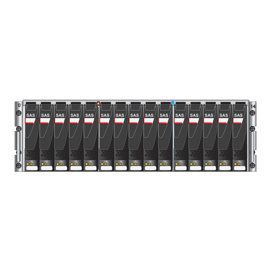
Bezel with key Documentation kit, including Installation Documentation kit, including Installation Guide, Quick Start poster, Configuration Guide, Quick Start poster, Configuration Worksheet and sheet of cable labels. Worksheet and sheet of cable labels. Figure 1 VNXe3300 DPE Shipping Contents VNXe3300 Installation Guide... - Page 5 The VNXe3300 DPE is a 3U component with either fifteen 3.5” drives or twenty-five 2.5” drives as shown in . The VNXe3300 can use either one of the two DAEs shown in Figure 1 on page 4 Figure 2 One is a 3U fifteen disk 3.5” drive DAE. The other is a 2U twenty-five disk 2.5” drive DAE. All DAEs are optional.
-
Page 6: Detaching The Dpe From The Shipping Material
The DPE is attached with 4 screws, two on each side, to the shipping container. Unscrew the shipping screws to remove the DPE from the container. Disk Processor enclosure Remove shipping screws 4 places, 2 screws on each side Figure 3 Removing the DPE from the shipping container VNXe3300 Installation Guide... -
Page 7: Prepare Your System
• DNS and NTP servers accessible from the VNXe system (recommended) • Windows Domain Controller (recommended) • SMTP server network connection to the VNXe3300 and the management host (optional) Network If you are using the VNXe Connection Utility, the management port and login information required... - Page 8 • At least 100 MB of free space • Connection on same LAN subnet as your VNXe system (recommended) • Web browser* (Internet Explorer, Mozilla Firefox, Google Chrome) • Adobe Flash Player* *Supported versions are listed in the release notes. VNXe3300 Installation Guide...
-
Page 9: Rack & Install
Rack & Install Install the disk processor enclosure (DPE) Install the DPE rails Install the DPE rails first, at the bottom of the space reserved for the VNXe system in your cabinet. Any DAEs should be installed above the DPE. 1. -
Page 10: Install The Disk Processor Enclosure
3. Insert four screws into the DPE bracket screw holes and into the cabinet as shown in Figure 6 . It may be easier to install the screws working in a diagonal pattern, such as bottom on page 11 left and top right, bottom right and top left. VNXe3300 Installation Guide... - Page 11 4. When the DPE is in place, tighten all of the screws. Front 4 screws hold the disk-processor in place (2 per side) VNXe-000768 Figure 6 Installing the DPE Note: Figure 6 shows a DPE with 3.5” disks. The installation of a DPE with 2.5” disks is identical. Install the disk processor enclosure (DPE)
-
Page 12: Install Disk Array Enclosures (Daes)
, insert one screw into the rail’s bottom threaded screw hole. Figure 8 Rear Detail Insert the alignment pins Alignment pins Front 2 screws 2 screws VNX-000216 2 screws Figure 7 Installing the 3U DAE rails VNXe3300 Installation Guide... -
Page 13: Install The Disk Array Enclosures
2 screws Front Rear detail 1 screw 1 screw 2 screws VNX-000755 Figure 8 Installing the 2U DAE rails 4. Insert two retention screws from the back of the cabinet to attach the rail. 5. Repeat steps 2-4 to attach the right DAE rail, making sure that the right rail is level with the left rail 6. - Page 14 3. When the DAE is in place, tighten all of the screws. Front VNXe-000767 4 screws hold the component in the cabinet (2 per side) Figure 9 Installing a 3U DAE VNXe3300 Installation Guide...
-
Page 15: Cable The Dpe To Dae
Front Front detail Brackets are attached to the components VNX-000756 Figure 10 Installing a 2U DAE 4. Repeat as necessary for additional DAEs. Cable the DPE to DAE Cabling between the DPE and DAEs uses Serial Attached SCSI (SAS) cables. The connectors on SAS cables have icons indicating the port for each end. - Page 16 1 GbE 1 GbE iSCSI iSCSI 6Gb SAS 6Gb SAS 1 X4 1 X4 0 X4 0 X4 SP A SAS 0 SP B SAS 0 Figure 12 SAS cabling between the DPE and the first DAE (3U) VNXe3300 Installation Guide...
- Page 17 Rear LCC B LCC A LCC B LCC A 1 GbE 1 GbE iSCSI iSCSI 6Gb SAS 6Gb SAS 1 X4 1 X4 0 X4 0 X4 SP A SAS 0 SAS 0 VNXe-000761 Figure 13 SAS cabling between the DPE and the first DAE (2U) All DAEs in the system are connected to the same bus.
-
Page 18: Attach Storage Processors To The Network
2. Connect two Ethernet cables from the RJ45 ports labeled management to the LAN from which you will configure the VNXe3300 system. 3. Connect two Ethernet cables from Ethernet port 2 to the LAN from which you will access your data on the VNXe system. -
Page 19: Power Up
Power up DC-powered VNXe3300 Enclosures Note: AC powered installation is shown here. For DC power, refer to the Installation and Operation Guide 1. Verify that the cabinet circuit breakers are in the On position and power is connected to the cabinet. - Page 20 The LEDs will show the progression of the power. Green, blue, and amber activity lights blink during the power-on period. The SP Power LEDs will then become steady ON. Note: For information about powering down the system, see “Shut down the system” in the Unisphere online help system. VNXe3300 Installation Guide...
-
Page 21: Verify Status Leds
Verify status LEDs The illustrations and table below call out only the LEDs that you need to verify to ensure that the system powered up correctly. DPE Rear View Power Power 1 GbE 1 GbE iSCSI iSCSI 6Gb SAS 6Gb SAS 1 X4 1 X4 0 X4... - Page 22 VNXe3300 Hardware Information Guide provides more details on all system LEDs. DPE fault/status DPE Power 3U, 15 disk DPE front Disk drive Disk drive fault/status power DPE fault/status DPE Power 3U, 25 disk DPE front Disk drive Disk drive power...
-
Page 23: Attach The Bezels
Attach the bezels 1. Locate the bezels for each installed component. 2. Attach the bezel that corresponds to each component. Each bezel can be locked in place by turning the key one quarter-turn clockwise. Front VNXe-000762 Press to attach the bezels Figure 19 Attaching the bezels Note: 2U bezels attach in the same way as the 3U bezels shown in Figure... -
Page 24: Connect
“Manually Assigning a Static VNXe Management Port IP Address” on page 25 2. Open a web browser and access the VNXe management interface specifying the following as a URL in the browser's address bar: serial_number .domain VNXe3300 Installation Guide... -
Page 25: Manually Assigning A Static Vnxe Management Port Ip Address
Where: URL string Description serial_number Serial number of your VNXe. You can find this in the packing materials that came with your VNXe (for example, FM100000000017). It is also on the PSNT tag on the back of the DPE. Network domain on which the VNXe system is located (for example, domain mylab.emc.com) Based on the examples provided in the table, the URL to the VNXe system would be:... - Page 26 Open a web browser to the IP address assigned to the VNXe system. 3. Continue with the steps in the VNXe Quick Start poster. The VNXe Quick Start poster provides an overview of the steps remaining to configure, register, license, and update the software on your system. VNXe3300 Installation Guide...
Need help?
Do you have a question about the VNXe3300 and is the answer not in the manual?
Questions and answers