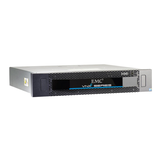
EMC2 VNXe3100 Manual
Adding input/output modules
Hide thumbs
Also See for VNXe3100:
- Upgrading (14 pages) ,
- Quick start manual (9 pages) ,
- Replacing instructions (7 pages)
Table of Contents
Advertisement
Before you start
Tasks to add I/O modules
®
EMC
VNXe3100/VNXe3150
Adding Input/Output Modules
P/N 300-012-213
REV 03
This document describes how to add input/output (I/O) modules to a VNXe3100 or
VNXe3150 disk processor enclosure (DPE). For information on how to upgrade the existing
I/O modules in a VNXe3100 or VNXe3150 DPE to a different type of I/O module, refer to
the document for upgrading I/O modules in a VNXe3100 or VNXe3150 system.
Before you start the procedure, refer to your EMC® VNXe™ online help (Servicing your
system > Adding or replacing faulted hardware components > Add a new hardware
component) for instructions on how to handle hardware components. Make sure you have
a matched pair of new I/O modules; you cannot install just one.
This procedure involves storage processor (SP) reboots coordinated to ensure that at
least one SP is running at all times. During an SP reboot, data will be unavailable to front-
or back-end connections that are not duplicated on the peer SP.
You add one I/O module to one SP at a time.
Task 1: Preparing the storage processor (SP) for service ............................................ 2
◆
Task 2: Remove the SP assembly............................................................................... 3
◆
Task 3: Remove the SP top cover ............................................................................... 4
◆
Task 4: Remove the filler module............................................................................... 5
◆
Task 5: Install the I/O module ................................................................................... 6
◆
Task 6: Replace the SP top cover ............................................................................... 7
◆
Task 7: Install the SP assembly ................................................................................. 7
◆
Task 8: Reboot the storage processor ........................................................................ 8
◆
Task 9: Verify that the new I/O module is recognized................................................. 8
◆
Task 10: Add the I/O module to SP B......................................................................... 9
◆
Task 11: Commit the new I/O modules ...................................................................... 9
◆
Advertisement
Table of Contents

Summary of Contents for EMC2 VNXe3100
-
Page 1: Table Of Contents
VNXe3150 disk processor enclosure (DPE). For information on how to upgrade the existing I/O modules in a VNXe3100 or VNXe3150 DPE to a different type of I/O module, refer to the document for upgrading I/O modules in a VNXe3100 or VNXe3150 system. -
Page 2: Task 1: Preparing The Storage Processor (Sp) For Service
Service mode and is receiving active power. 6. Wait until the SP fault LED is flashing alternating amber and blue before continuing to the next task. e0 e1 1 GBE 6Gb SAS 6Gb SAS SP fault EMC VNXe3100/VNXe3150 — Adding Input/Output Modules... -
Page 3: Task 2: Remove The Sp Assembly
3. Pinch the orange tabs and pull the latches to the sides to eject the SP assembly from the chassis. 4. Pull the SP assembly straight out of the chassis and place it on a static-free surface. CL4682 EMC VNXe3100/VNXe3150 — Adding Input/Output Modules... -
Page 4: Task 3: Remove The Sp Top Cover
Tasks to add I/O modules Task 3: Remove the SP top cover 1. Press the blue button on the cover. 2. Push the cover straight back 1/4 inch. 3. Lift the cover up. CL4683 EMC VNXe3100/VNXe3150 — Adding Input/Output Modules... -
Page 5: Task 4: Remove The Filler Module
1. Lift the blue latch carefully until it ejects the filler module from the connector. 2. Lift the module out and away from the canister and place it on a static free surface. CL4688 EMC VNXe3100/VNXe3150 — Adding Input/Output Modules... -
Page 6: Task 5: Install The I/O Module
3. With the module aligned and parallel to the CPU board, press the latch down to fully seat the module in the connector. 4. Push down on the force point indicated on the I/O module to ensure that the module is completely seated on the processor board. CL4689 EMC VNXe3100/VNXe3150 — Adding Input/Output Modules... -
Page 7: Task 6: Replace The Sp Top Cover
3. Close the right and left latches to fully seat the SP assembly in the chassis. An audible click indicates that the latches are secure. CL4687 The SP begins powering up immediately after connection to an active AC power source. EMC VNXe3100/VNXe3150 — Adding Input/Output Modules... -
Page 8: Task 8: Reboot The Storage Processor
Warning status icon because it has not been committed yet. • In the graphical view, the module should be highlighted yellow. If the system health monitor shows the module as faulted, contact your service provider. EMC VNXe3100/VNXe3150 — Adding Input/Output Modules... -
Page 9: Task 10: Add The I/O Module To Sp B
• In the System Components list, the new module should be marked with a status OK icon: • In the graphical view, the module should be highlighted green. If the system health monitor shows the new module as faulted, contact your service provider. EMC VNXe3100/VNXe3150 — Adding Input/Output Modules... - Page 10 All other trademarks used herein are the property of their respective owners. For the most up-to-date regulatory document for your product line, go to the technical documentation and advisories section on EMC Online Support. EMC VNXe3100/VNXe3150 — Adding Input/Output Modules...


Need help?
Do you have a question about the VNXe3100 and is the answer not in the manual?
Questions and answers