EMC2 VNX Series Hardware Information Manual
Hide thumbs
Also See for VNX Series:
- Hardware information manual (138 pages) ,
- Installation manual (82 pages) ,
- Manual (15 pages)
Advertisement
Table of Contents
- 1 Table of Contents
- 2 Product Software and Hardware Release Revisions
- 3 Revision History
- 4 Where to Get Help
- 5 How this Document Is Organized
- 6 Related Documentation
- 7 Overview
- 8 VNX5100 Block Product Description
- 9 Hardware Features
- 10 System Component Description
- 11 Disk-Array Enclosure
- 12 Cabling Overview
- 13 VNX5100 Block DAE Cabling
- Download this manual
®
™
EMC
VNX
Family
™
VNX5100
Hardware Information Guide
REV A03
October, 2011
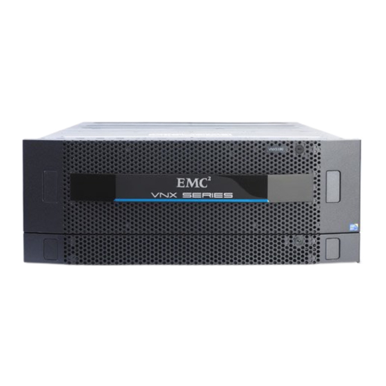
This guide describes one of five models available in the VNX Series, the EMC
VNX5100™. This document provides an overview of the architecture, features, and
components of the Block VNX5100 platform. The specific aspects of the VNX5100
platform and its major components include the front and rear connectors and LED
indicators on the 3U, 15 (3.5-inch) or 3U, 25 (2.5-inch) disk processor enclosure (DPE),
the 1U standby power supply (SPS), and the 3U, 15 (3.5-inch) or the 2U, 25 (2.5-inch) disk
drive disk-array enclosure DAE.
This guide is available online at https://mydocs.emc.com/VNX/. Go to the About VNX
section, and then select Learn about VNX. Next, follow the steps in the wizard.
Topics include:
Product software and hardware release revisions ...................................................... 4
◆
Revision history ........................................................................................................ 4
◆
Where to get help...................................................................................................... 4
◆
How this document is organized ............................................................................... 5
◆
Related documentation............................................................................................. 5
◆
Overview................................................................................................................... 6
◆
VNX5100 Block product description.......................................................................... 7
◆
Hardware features..................................................................................................... 8
◆
System component description ............................................................................... 10
◆
Disk-array enclosure................................................................................................ 31
◆
Cabling overview..................................................................................................... 47
◆
VNX5100 Block DAE cabling.................................................................................... 48
◆
®
Advertisement
Table of Contents

Related Manuals for EMC2 VNX Series


Summary of Contents for EMC2 VNX Series
-
Page 1: Table Of Contents
October, 2011 ® This guide describes one of five models available in the VNX Series, the EMC VNX5100™. This document provides an overview of the architecture, features, and components of the Block VNX5100 platform. The specific aspects of the VNX5100 platform and its major components include the front and rear connectors and LED indicators on the 3U, 15 (3.5-inch) or 3U, 25 (2.5-inch) disk processor enclosure (DPE),... -
Page 2: Product Software And Hardware Release Revisions
Product software and hardware release revisions Product software and hardware release revisions As part of an effort to improve its product lines, EMC periodically releases revisions of its software and hardware. Therefore, some functions described in this document might not be supported by all versions of the software or hardware currently in use. -
Page 3: How This Document Is Organized
How this document is organized How this document is organized The major sections of this guide are listed in the following table. Title Description “Overview” on page 6 Describes the software and hardware features of a typical VNX5100 along with a front view example of the VNX5100. “VNX5100 Block product Describes and shows the front and rear views of a typical description”... -
Page 4: Overview
Intel Xeon-based PCI Express 2.0 processors and delivers File (NAS) functionality via two to eight Data Movers and Block (iSCSI, FCoE, and FC) storage via dual storage processors using a full 6-Gb/s SAS disk drive topology. The VNX Series is targeted at the entry-level to high-end/large-capacity storage environments that require advanced features, flexibility and configurability. -
Page 5: Vnx5100 Block Product Description
VNX5100 Block product description VNX5100 Block product description This section shows an example of the front and rear views of a Block VNX5100 platform. Note: A fully configured VNX5100 platform includes up to four 3U DAEs (a maximum of 75 3.5-inch disk drives) or up to two 2U DAEs (a maximum of 75 2.5-inch disk drives). -
Page 6: Hardware Features
VNX5100 Block product description Note: Figure 2 on page 7 Figure 3 on page 7 are examples of a VNX5100 platform (front and rear views). These figures are example of what a basic VNX5100 platform looks like and are for illustrative purposes only. Hardware features Contained in a 4U architecture, the VNX5100 platform weighs approximately 73.4 lb (33.29 kg) to 96.4 lb (43.73 kg) fully loaded... - Page 7 VNX5100 Block product description • On the front of the DPE, three types of disk drives are supported in two disk drive carrier types; 3U, 15 (3.5-inch) disk drive carrier (Figure 4 on page 12) and 3U, 25 (2.5-inch) disk drive carrier (Figure 5 on page 13).
-
Page 8: System Component Description
System component description System component description This section describes the Block VNX5100 platform components. Included in this section are illustrations and descriptions of the front and rear connectors as well as the LED indicators. First, the components of the VNX5100 are described in two views. “VNX5100 front view”... - Page 9 System component description Drive carrier The disk drive carriers are metal and plastic assemblies that provide smooth, reliable contact with the enclosure slot guides and midplane connectors. Each carrier has a handle with a latch and spring clips. The latch holds the disk drive in place to ensure proper connection with the midplane.
- Page 10 System component description 3U, 15 disk drive DPE front view On the front, the Block VNX5100 platform 3U, 15 (3.5-inch) DPE carrier includes the following: 3.5-inch 6-Gb/s SAS or 6-Gb/s NL-SAS disk drives (hot-swappable) ◆ Status LEDs ◆ Figure 4 shows the location of these disk drives and Status LEDs.
- Page 11 System component description Table 2 VNX5100 platform 3U, 15 DPE and disk drive LEDs (continued) Color State Description Disk drive on/activity Green Powering and powered up (location 5) Blinking, mostly Disk drive is on with I/O activity Blinking at Disk drive is spinning up or down constant rate normally Blinking, mostly...
- Page 12 System component description Table 3 describes the Block VNX5100 platform 3U, 25 DPE and disk drive status LEDs. Table 3 VNX5100 platform 3U, 25 DPE and disk drive status LEDs Color State Description DPE fault (location 2) Amber Fault has occurred DPE power (location 3) Blue Powering and powered up...
- Page 13 System component description On the rear of the DPE, viewing from left to right, each DPE consists of the following connectors, status LEDs, latch handles, and so on: AC power supply/cooling module ◆ • Power in (recessed) connector (plug) • Power supply status LEDs (power on and fault) •...
- Page 14 System component description Figure 7 shows the location of the SP components. Cover Cover Do not remove Do not remove fibre 6Gb SAS 0 X4 VNX-000285 AC power in connector (recessed plug) Two RJ-45 (management and service laptop) connectors (labeled with a network management symbol and a wrench symbol, respectively) Power supply fault LED (amber)
- Page 15 System component description SP AC power supply module Figure 8 shows an example of the SP AC power supply/cooling module with a power in recessed connector (plug) and status LEDs. The SP is cooled by this power supply/cooling on top. Do not remove the SP power supply/cooling module while the SP is plugged in.
- Page 16 System component description Table 5 SP LEDs (continued) Color State Description Fault Amber Fault (location 11) — No fault or power off Power Green Power on (location 12) — Power off, verify connection SP Input/output ports and connectors The Block VNX5100 platform SP supports the following I/O ports on the rear: Two 6-Gb/s SAS PCI Gen 2 x4 ports (labeled 6Gb SAS 0 x4 and 1 x4);...
- Page 17 System component description Table 6 lists the SP 6-Gb/s SAS port pin signals used on the connector. Table 6 SP 6-Gb/s SAS port connector pinout Signal Signal Rx 0+ Tx 0+ Rx 0- Tx 0- Rx 1+ Tx 1+ Rx 1- Tx 1- Rx 2+ Tx 2+...
- Page 18 System component description 8-Gb/s FC ports The Block VNX5100 platform SP comes with four optical (fibre) 8-Gb/s FC ports (labeled 8GB fibre 2, 3, 4, and 5). Only two ports are supported (2 and 3) (ports 4 and 5 are not used, they will be covered) on the rear of each SP (A and B).
- Page 19 System component description CNS-001102 Orange cable Rubber gasket (jacket), receive (RX) Rubber gasket (jacket), send or transmit Ferrule (connector end to SFP+ module) (TX) Figure 12 Example of LC-type connectors Figure 13 shows an example of the SP 8-Gb/s FC connector with an SFP+ in slots 2 and 3. fibre VNX-000284 Figure 13 Example of SP 8-Gb/s FC connector with an SFP+ in slots 2 and 3...
- Page 20 System component description Network management and service laptop Ethernet (RJ-45) ports The SP Ethernet (RJ-45) ports are LAN ports not WAN ports. LAN ports contain safety extra-low voltage (SELV) circuits, and WAN ports contain telephone-network voltage (TNV) circuits. Some LAN and WAN ports both use RJ-45 connectors. Use caution when connecting cables.
- Page 21 System component description Network management and service laptop Ethernet (RJ-45) port and connector (adapter) — Figure 15 shows an example of the Ethernet (RJ-45) port and cable connector. 1 2 3 4 5 6 7 8 VNX-000111 Figure 15 Network management and service laptop Ethernet (RJ-45) port and connector (adapter) Table 10 lists the SP network management and service laptop Ethernet (RJ-45) pin signals used on the connector.
- Page 22 System component description Table 11 describes the link/activity and connection speed associated with the SP Ethernet (RJ-45) port LEDs. Table 11 Network management and service laptop Ethernet (RJ-45) port LEDs Color State Description Left, link Green Network/link connection (location 1) Green Blinking Transmit/receive activity...
- Page 23 System component description Table 12 Serial RS-232/EIA 232 (micro DB-9) connector (socket) pinout (continued) DB-9 Pin Signal Description Request to send Clear to send Ring indicator (Not Used) SP CPU module null modem (micro DB-9 to DB-9 serial) cable The cable connecting the SP to the PC or service laptop is a micro DB-9 cable (plug) to serial DB-9 (socket).
- Page 24 System component description Table 13 lists the SP serial RS-232/EIA 232 (micro DB-9) pin signals used on the connector. Table 13 Serial RS-232/EIA 232 (micro DB-9) connector (socket) pinout DB-9 Pin Signal Description Carrier detect Received data Transmitted data Data terminal ready Ground Data set ready Clear to send...
- Page 25 System component description Standby power supply The Block VNX5100 platform includes one to two 1U, 1.2-kilowatt standby power supplies (SPSs) to maintain power to the VNX5100 platform SP during power loss. Within the SPS, a built-in DC battery pack is charged by way of an AC-DC converter. AC input power from the power distribution unit (PDU) goes into the SPS AC power inlet to the AC-DC converter.
- Page 26 System component description Two SPSs An additional SPS can be added for redundancy. When only one SPS is used, the AC power out connectors for the SPS supply AC power to both SP A and SP B. It is important to cable each SPS so that it connects completely to either the A side or the B side.
- Page 27 System component description Table 14 describes the SPS LEDs. Table 14 SPS LEDs Color State Description SPS power Green SPS ready and operating normally; battery fully charged Blinking On/battery charging — Off/disconnected SPS battery Amber AC line power is no longer available and the SPS is (On battery) supplying AC output power from the DC-AC convertor by way of the DC battery.
- Page 28 System component description VNX-000290 Figure 23 SPS RJ-12 port Table 15 lists the SPS (RJ-12) pin signals used on the connector. Table 15 SPS (RJ-12) port and connector pinout RJ-45 pin Signal Description RTS/DSR Ready to send Data transmit ready Shield Shield Transmit data...
-
Page 29: Disk-Array Enclosure
Disk-array enclosure Disk-array enclosure Lifting the DAE and installing it to or removing it from a rack is a two-person job. If needed, use an appropriate lifting device. A fully loaded 2U DAE or 3U DAE weighs approximately 45 lb (20.41 kg) or 68 lb (30.84 kg), respectively. The Block VNX5100 platform supports two types of disk-array enclosures (DAEs) across a 6-Gb/s SAS bus: 3U, 15 (3.5-inch) DAE... - Page 30 Disk-array enclosure Midplane A midplane separates the front-facing disk drives from the rear-facing LCCs and power supply/cooling modules. It distributes power and signals to all components in the enclosure. LCCs, power supply/cooling modules, and disk drives plug directly into the midplane.
- Page 31 Disk-array enclosure 3U, 15 (3.5-inch) DAE front view On the front, viewing from left to right, the Block VNX5100 platform 3U, 15 (3.5-inch) disk drive DAE carrier includes the following hardware components: 6-Gb/s SAS, 6-Gb/s NL-SAS, or Flash disk drives (hot-swappable) ◆...
- Page 32 Disk-array enclosure Table 16 3U 15 (3.5-inch) DAE and disk drive LEDs (continued) Color State Description Disk drive on/activity Green Powering and powered up (location 5) Blinking, mostly Disk drive is on with I/O activity Blinking at Disk drive is spinning up or down constant rate normally Blinking, mostly...
- Page 33 Disk-array enclosure Note: An LCC might be in either the A slot, as shown, or the B slot above it, depending on the DAE placement within a system. For example, the front DAE in some systems is in slot A; the rear enclosure LCC is inverted, and in slot B. Figure 26 shows an example of the rear view of a 3U, 15 (3.5-inch) disk drive DAE.
- Page 34 Disk-array enclosure 3U, 15 (3.5-inch) DAE AC power supply/cooling module Figure 27 shows an example of the 3U, 15 (3.5-inch) disk drive DAE AC power supply/cooling module with a power in (recessed) connector (plug) and status LEDs. Power supply in Power on LED Power fault LED Fan fault LED...
- Page 35 Disk-array enclosure The 3U, 15 (3.5-inch) DAE LCC input/output ports and connectors The 3U, 15 (3.5-inch) DAE LCC supports the following I/O ports on the rear: Two 6-Gb/s SAS PCI Gen 2 x 4 ports ◆ One management (RJ-45) connector ◆...
- Page 36 Disk-array enclosure Table 18 6-Gb/s SAS port connector pinout (continued) Signal Signal Rx 3+ Tx 3+ Rx 3- Tx 3- 6-Gb/s SAS port LEDs and port direction (input or output) Figure 29 shows the LCC 6-Gb/s SAS port LED—a bi-color (blue/green) LED next to the connector, either left or right—that indicates the link/activity of the SAS port.
- Page 37 Disk-array enclosure Management (RJ-12) connector Note: The management Ethernet (RJ-12) LCC to SPS connector is not used at this time. Figure 30 shows the management port connector (labeled with two symbols; one depicting a telephone handset with a line through it and the other depicting a battery). The handset with a line through it symbol means that you cannot connect telephone type circuits to this connector (see the following WARNING).
- Page 38 Disk-array enclosure Table 20 describes the bus (loop) indicator status LEDs. Table 20 LCC bus (loop) status LEDs Color State Description Power fault Amber Fault — No fault or power off Power on Green Power on — Power off 2U, 25 (2.5-inch) DAE front view On the front, viewing from left to right, the Block VNX5100 platform 2U, 25 (2.5-inch) DAE includes the following hardware components: 6-Gb/s SAS, 6-Gb/s NL-SAS, or Flash disk drives (hot-swappable)
- Page 39 Disk-array enclosure Table 21 describes the 2U, 25 (2.5-inch) DAE and disk drive status LEDs. Table 21 2U, 25 (2.5-inch) DAE and disk drive status LEDs Color State Description DPE fault (location 2) Amber Fault has occurred DPE power (location 3) Blue Powering and powered up —...
- Page 40 Disk-array enclosure Figure 33 shows an example of the rear view of a 2U, 25 (2.5-inch) disk drive DAE. VNX-000280 LLC B power supply LED (on, green) LCC B bus ID LCC B power supply fault LED (on, amber) LCC B power and fault LEDs LCC B AC power supply power in (recessed DAE enclosure ID plug)
- Page 41 Disk-array enclosure Table 22 describes the 2U, 25 (2.5-inch) DAE power supply/cooling module LEDs. Table 22 2U, 25 (2.5-inch) DAE AC power supply/cooling module LEDs Color State Description Power fault Amber Fault Blinking During power shutdown and during overvoltage and undervoltage protection (OVP/UVP) fault —...
- Page 42 Disk-array enclosure Figure 35 shows an example of the port connector (socket) and cable connector (plug) with pull tab. Pin A1 VNX-000094 Figure 35 6-Gb/s SAS port and cable connector Table 23 lists the 6-Gb/s SAS port pin signals used on the connector. Table 23 6-Gb/s SAS port connector pinout Signal Signal...
- Page 43 Disk-array enclosure Latch handle 6 Gb/s SAS port Link LED VNX-000274 Figure 36 6-Gb/s SAS port LED Table 24 describes the 6-Gb/s port LEDs. Table 24 6-Gb/s SAS port LEDs Color State Description Link/activity Blue All lanes are running at 6 GB/s Green One or more lanes is not running at full speed or disconnected...
- Page 44 Disk-array enclosure VNX-000106 Figure 37 LCC RJ-12 port The cable connecting the LCC to the SPS is an RJ-12 to RJ-12. It has an RJ-12 adapter (LCC side) on one end and a RJ-12 (SPS side) adapter on the other end. LCC enclosure ID (enclosure address) and bus ID On the rear of the LCC (A and B), an LCC enclosure ID indicator is provided.
-
Page 45: Cabling Overview
LAN cabling, and so on. Cable label wraps Each VNX series platform comes with a cable label wrap guide or set of cable label wraps to affix to the cables on your VNX series platform. These labels should be affixed to the appropriate cables as you connect the cables to your VNX series platform. -
Page 46: Vnx5100 Block Dae Cabling
VNX5100 Block DAE cabling VNX5100 Block DAE cabling IMPORTANT The DAE(s) that are to be directly connected to the DPE need to be located close enough to the DPE so that the DPE-to-DAE interconnect cables (that are provided with every DAE) can be routed and connected to the DPE. - Page 47 VNX5100 Block DAE cabling Note: On the DPE and DAE, each cable connector includes a symbol to denote the direction the cable needs to connect to. The cable connector that has a double circle symbol is the input to the device. The cable connector with the double diamond symbol is the output from the device.
- Page 48 VNX5100 Block DAE cabling DAE 2 2U, 25 disk Optional LCC B LCC A DAE 1 3U, 15 disk Optional LCC B LCC A SP A SP B SAS 1 fibre fibre 1 X4 6Gb SAS SAS 1 6Gb SAS 0 X4 0 X4 SP A SAS 0...
- Page 49 VNX5100 Block DAE cabling The cables shown in Figure 41 on page 52 are: Note: The cable colors shown in the example are orange for Bus 0 and blue for Bus 1. Cable 1, blue, DPE to 1 DAE (labels SP A SAS 1 to LCC A) ◆...
- Page 50 VNX5100 Block DAE cabling 40U rack 3U DAE (15 disks per DAE) EA 2/Bus 0 Maximum number of DAEs 4 Maximum number of disks 75 EA 1/Bus 1 EA 1/Bus 0 EA 0/Bus 1 Bus 1 Bus 1 Bus 0 Bus 0 SP B SP A...
- Page 51 VNX5100 Block DAE cabling Stacked cabling with four DAEs in a VNX5100 Block platform Figure 42 on page 54 shows a third example of a VNX5100 platform with four DAEs (all are 3U, 15 disk drive DAEs) or a VNX5100 platform with a total of 75 disk drives (with the DPE a 3U, 15 disk drive device).
- Page 52 VNX5100 Block DAE cabling 40U rack 3U DAE (15 disks per DAE) Bus 0 EA 1/Bus 1 Maximum number of DAEs 4 Maximum number of disks 75 EA 0/Bus 1 Bus 1 Bus 1 EA 2/Bus 0 EA 1/Bus 0 Bus 0 SP A SP B...
- Page 53 VNX5100 Block DAE cabling EMC VNX5300 Hardware Information Guide...
- Page 54 VNX5100 Block DAE cabling Copyright © 2011 EMC Corporation. All rights reserved. Published in the USA. Published October, 2011 EMC believes the information in this publication is accurate as of its publication date. The information is subject to change without notice.
Need help?
Do you have a question about the VNX Series and is the answer not in the manual?
Questions and answers