Table of Contents
Advertisement
Quick Links
Advertisement
Table of Contents

Related Manuals for EMC2 VxRail E Series


Summary of Contents for EMC2 VxRail E Series
- Page 1 VxRail Appliances on 14th Generation PowerEdge E Series Owner's Manual...
- Page 2 © Copyright 2017 Dell Inc. or its subsidiaries. All rights reserved. Published November 2017 Dell believes the information in this publication is accurate as of its publication date. The information is subject to change without notice. THE INFORMATION IN THIS PUBLICATION IS PROVIDED “AS-IS.“ DELL MAKES NO REPRESENTATIONS OR WARRANTIES OF ANY KIND WITH RESPECT TO THE INFORMATION IN THIS PUBLICATION, AND SPECIFICALLY DISCLAIMS IMPLIED WARRANTIES OF MERCHANTABILITY OR FITNESS FOR A PARTICULAR PURPOSE.
-
Page 3: Table Of Contents
CONTENTS Chapter 1 Overview Front view....................6 Left control panel view..............7 Right control panel view..............10 Back view of the appliance................11 Power supply unit indicator codes...............12 Drive indicator codes.................. 15 NIC indicator codes..................16 iDRAC Direct LED indicator codes...............17 Locating serial number of your appliance............ 18 Looking up your appliance serial number in VxRail Manager... - Page 4 CONTENTS Using SolVe Desktop application for VxRail Series hardware tasks.....40 System memory..................40 General memory module installation guidelines......42 Expansion cards and expansion card riser...........42 Expansion card installation guidelines..........42 Chapter 7 Getting help Contacting EMC..................46 Registering for online support..............46 Accessing support resources..............
-
Page 5: Overview
CHAPTER 1 Overview ™ The VxRail E Series appliance is a hyper-converged appliance that supports: Up to two Intel Xeon Processor Scalable Family processors 10 x 2.5 inch hard drives or solid state drives (SSDs) 24 DIMM slots Two AC or DC redundant power supply units Note The appliance supports only internal, hot swappable hard drives. -
Page 6: Front View
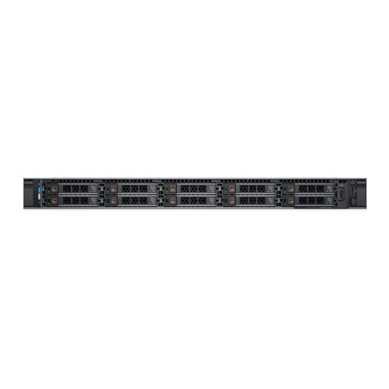
Overview Front view You can access the components such as power button, NMI button, appliance identification tag, appliance identification button, and USB ports from the front of the appliance. The diagnostic LEDs are prominently located on the front panel. The hot swappable hard drives are accessible from the front panel. -
Page 7: Left Control Panel View
Overview Left control panel view Figure 2 Left control panel view The table below describes the left control panel features: Table 2 Left control panel features Item Indicator Icon Description Status LED Indicate the status of the appliance. For more indicators information, see the Status LED indicators... - Page 8 Overview Table 3 Status LED indicators and descriptions (continued) Icon Description Condition Corrective action the host adapter configuration utility program. Temperature The indicator turns Ensure that none of the following conditions indicator solid amber if the exist: appliance A cooling fan has been removed or has experiences a failed.
- Page 9 Overview Appliance health and appliance ID indicator codes The appliance health and appliance ID indicator is located on the left control panel of your appliance. Figure 3 Appliance health and appliance ID indicators This table describes the appliance health and appliance ID indicators. Item 1 indicates Solid blue where the condition indicates that the appliance is turned on, appliance is healthy, and appliance ID mode is not active.
-
Page 10: Right Control Panel View
Overview Right control panel view Figure 4 Right control panel view The table below describes the right control panel features Table 5 Right control panel features Item Indicator, Icon Description button, or connector Power button Indicates if the appliance is turned on or off. Press the power button to manually turn on or off the appliance. -
Page 11: Back View Of The Appliance
Overview Back view of the appliance You can access the components such as appliance identification button, power supply sockets, cable management arm connectors, iDRAC storage media, NIC ports, and USB ports from the back of the appliance. Most of the expansion card ports can be accessed from the back panel. -
Page 12: Power Supply Unit Indicator Codes
Overview Table 6 10 X 2.5 inch drive appliance with 3 PCIe expansion slot (continued) Item Ports, panels, Icon Description or slots VGA port Enables you to connect a display device to the appliance. For more information, see the Technical Specifications section. - Page 13 Overview Figure 6 AC PSU status indicator (continued) 1. AC PSU status indicator/handle This table describes the AC PSU status indicators and what condition is the PSU when the power indicator light is green, flashing green, flashing amber, and when it is not lit. Table 7 AC PSU status indicators Convention Power indicator...
- Page 14 Overview Figure 7 DC PSU status indicator 1. DC PSU status indicator This table describes the DC PSU status indicators and what condition is the PSU when the power indicator light is green, flashing green, flashing amber, and when it is not lit. Table 8 DC PSU status indicators Convention Power indicator Condition...
-
Page 15: Drive Indicator Codes
Overview Table 8 DC PSU status indicators (continued) Convention Power indicator Condition pattern CAUTION Combining AC and DC PSU is not supported and triggers a mismatch. Not lit Power is not connected. Drive indicator codes Each hard drive carrier has an activity indicator and a status indicator. The indicators provide information about the current status of the hard drive. -
Page 16: Nic Indicator Codes
Overview Table 9 Drive indicator codes (continued) Drive status indicator code Condition Drive ready for removal. Note The drive status indicator remains off until all drives are initialized after the appliance is turned on. Drives are not ready for removal during this time. -
Page 17: Idrac Direct Led Indicator Codes
Overview Table 10 NIC indicators Convention Status Condition Link and activity indicators are The NIC is not connected to the network. Link indicator is green The NIC is connected to a valid network at its maximum port speed (1 Gbps or 10 Gbps). -
Page 18: Locating Serial Number Of Your Appliance
Overview Table 11 iDRAC Direct LED indicators Convention iDRAC Direct LED Condition indicator pattern Green Turns green for a minimum of two seconds to indicate the start and end of a file transfer. Flashing green Indicates file transfer or any operation tasks. Green and turns off Indicates that the file transfer is complete. -
Page 19: Locating Your Physical Vxrail Service Tag Number
Overview Locating your physical VxRail Service Tag number Locating your physical VxRail Service Tag number... - Page 20 Overview Your hardware is identified by a unique Service Tag number. The Service Tag is found on the front of the appliance by pulling out the information tag. Alternatively, the information may be on a sticker on the chassis of the appliance. This information is used by EMC to route support calls to the appropriate personnel.
-
Page 21: Documentation Matrix
CHAPTER 2 Documentation matrix The documentation matrix provides information on documents that you can refer while setting up and managing your appliance. Documentation matrix Table 13 Documentation matrix Document Provides information about... Location Software Documents Online help in the all admin tasks, licensing, and product VxRail Manager Online Help VxRail Manager architecture information. - Page 22 Documentation matrix VxRail Appliances on 14th Generation PowerEdge E Series Owner's Manual...
-
Page 23: Technical Specifications
CHAPTER 3 Technical specifications The technical and environmental specifications of your appliance are outlined in this section. Chassis dimensions.................... 24 Chassis weight....................24 Processor specifications..................25 specifications..................... 25 Battery specifications..................25 Expansion bus specifications................26 Memory specifications..................26 Storage controller specifications................26 Hard drive specifications..................26 Ports and connectors... -
Page 24: Chassis Dimensions
(29.61 inches) (30.42 inches) inches) inches) Chassis weight The table below shows the maximum weight of the VxRail E Series: Table 15 Chassis weight System Maximum weight (with all hard drives/SSDs) VxRail E Series 21.9 kg VxRail Appliances on 14th Generation PowerEdge E Series Owner's Manual... -
Page 25: Processor Specifications
Maximum weight (with all hard drives/SSDs) (48.28 lbs) Processor specifications The VxRail E Series appliance supports up to two Intel Xeon Processor Scalable Family processors. PSU specifications The VxRail E Series appliance supports two AC or DC power supply units (PSUs). -
Page 26: Expansion Bus Specifications
Hard drive specifications The VxRail E Series appliance supports SAS, SATA, Nearline SAS hard drives or SSDs. This table lists out the supported hard drive and SSD options for the VxRail E Series appliance: VxRail Appliances on 14th Generation PowerEdge E Series Owner's Manual... -
Page 27: Ports And Connectors Specifications
Data Terminal Equipment (DTE), 16550-compliant. VGA ports The Video Graphic Array (VGA) port enables you to connect the appliance to a VGA display. The VxRail E Series appliance supports one 15-pin VGA port on the front and back of appliance. Video specifications The VxRail E Series appliance supports integrated VGA controller with 4 MB SPI capacity. -
Page 28: Internal Dual Sd Module
Technical specifications This table describes the supported video resolution options: Table 21 Supported video resolution options Resolution Refresh rate (Hz) Color depth (bits) 640 x 480 60, 70 8, 16, 32 800 x 600 60, 75, 85 8, 16, 32 1024 x 768 60, 75, 85 8, 16, 32... - Page 29 Technical specifications Table 22 Temperature specifications (continued) Temperature Specifications Note Certain configurations may have ambient temperature restrictions. For more information see the Ambient temperature limitations section. Fresh air For information about fresh air, see Expanded Operating Temperature section. Maximum temperature gradient 20°C/h (68°F/h) (operating and storage) The table below shows the relative humidity specification during operations and...
-
Page 30: Particulate And Gaseous Contamination Specifications
Technical specifications The table below shows the maximum altitude specifications during operations and storage. Table 26 Maximum altitude specifications Maximum altitude Specifications Operating 3048 m (10,000 ft) Storage 12,000 m (39,370 ft) The table below shows the operating temperature de-rating specifications: Table 27 Operating temperature de-rating specifications Operating temperature de-rating Specifications... -
Page 31: Standard Operating Temperature
Technical specifications Table 28 Particulate contamination specifications (continued) Particulate contamination Specifications Note This condition applies only to data center environments. Air filtration requirements do not apply to IT equipment designed to be used outside a data center, in environments such as an office or factory floor. -
Page 32: Expanded Operating Temperature
Technical specifications Expanded operating temperature When the appliance is in continuous operation, the expanded operating temperature ranges from 5°C to 40°C at 5% to 85% RH with 29°C dew point. Outside the standard operating temperature (10°C to 35°C), the appliance can operate continuously in temperatures as low as 5°C and as high as 40°C. -
Page 33: Expanded Operating Temperature Restrictions
Technical specifications Expanded operating temperature restrictions Do not perform a cold startup below 5°C. The operating temperature specified is for a maximum altitude of 3050 m (10,000 ft). Redundant power supply units are required. Non-EMC qualified peripheral cards and/or peripheral cards greater than 25 W are not supported. - Page 34 Technical specifications Table 32 Configuration based ambient temperature restrictions Appliance Front Processor Processor Fan Type Ambient Backplane Thermal Heat Sink Restriction Design Power VxRail E 10 x 2.5 inch 200 W, 205 2 pipe 1U high High 30°C Series SAS/SATA performance performance Appliances...
-
Page 35: Initial Setup And Configuration
CHAPTER 4 Initial setup and configuration For assistance on installation and deployment services, contact your EMC account team or your reseller for installation services. WARNING During the VxRail deployment process, an iDRAC account named vxadmin or PTAdmin is created. This account provides hardware information to the VxRail Manager and is required for the VxRail Manager and the cluster to function properly. - Page 36 Initial setup and configuration VxRail Appliances on 14th Generation PowerEdge E Series Owner's Manual...
-
Page 37: Pre-Operating Systems
CHAPTER 5 Pre-operating systems You can manage basic settings and features of a appliance without booting to the operating system by using the appliance firmware. Note This appliance requires installation and deployment services. Do not rack this appliance, or turn on the power. Contact your EMC Account Team or your reseller for setting up your appliance. -
Page 38: Options To Manage The Pre-Operating System Applications
Pre-operating systems Options to manage the pre-operating system applications Your appliance has the following options to manage the pre-operating system applications: System Setup Boot Manager Lifecycle Controller Preboot Execution Environment (PXE) Note EMC has optimized your appliance and recommends that you do not change any of these settings. -
Page 39: Replacing And Adding Hardware
CHAPTER 6 Replacing and adding hardware Adding or replacing hardware component procedures on your VxRail E Series appliance, such as hard disk drives (HDDs), solid state drives (SSDs), and power supply units must be performed only by EMC certified service technicians. For certain hardware components, you may need to contact Customer Support for repair or replacement. -
Page 40: Using Solve Desktop Application For Vxrail Series Hardware Tasks
Replacing and adding hardware Using SolVe Desktop application for VxRail Series hardware tasks Step-by-step hardware component tasks such as replacement and upgrade procedures are available through the SolVe Desktop application. Before you begin You must have an online support account to use the SolVe Desktop application. WARNING The VxRail Series procedures in the SolVe Desktop application for replacing hardware or any upgrade procedures must be performed only by EMC certified... - Page 41 Replacing and adding hardware release tabs of the first socket are marked white and the second socket are marked black. Figure 13 Memory socket locations Memory channels are organized as follows: This tables describes memory channels and how the channels are organized. Table 33 Memory channels Processor Chan 0 Chan 1...
-
Page 42: General Memory Module Installation Guidelines
Replacing and adding hardware General memory module installation guidelines Note Memory configurations that fail to observe these guidelines can prevent your appliance from booting, stop responding during memory configuration, or operating with reduced memory. The following are the recommended guidelines for installing memory modules: RDIMMs and LRDIMMs must not be mixed. - Page 43 Replacing and adding hardware Table 34 Expansion card riser configurations Expansion PCIe slots on Processor Height Length Slot card riser the riser connection width Riser 1A Slot 1 Processor 1 Low Profile Half Length Slot 2 Processor 1 Low Profile Half Length Riser 2A Slot 3...
- Page 44 Replacing and adding hardware VxRail Appliances on 14th Generation PowerEdge E Series Owner's Manual...
-
Page 45: Getting Help
CHAPTER 7 Getting help Contacting EMC....................46 Registering for online support................46 Accessing support resources................46 Getting help... -
Page 46: Contacting Emc
Getting help Contacting EMC You can link your Online Support account with VxRail Manager and access support resources without having to log in separately. Note If you plan to set up EMC Secure Remote Services (ESRS), you must link your Online Support account to VxRail Manager under the same ID or it may not work properly.
Need help?
Do you have a question about the VxRail E Series and is the answer not in the manual?
Questions and answers