
Related Manuals for Tektronix Keithley 4225-PMU


Summary of Contents for Tektronix Keithley 4225-PMU
- Page 1 tek.com/keithley Model 4200A-SCS Pulse Card (PGU and PMU) User's Manual 4200A-PMU-900-01 Rev. B March 2023 *P4200A-PMU-900-01B* 4200A-PMU-900-01B...
- Page 2 Model 4200A-SCS Pulse Card (PGU and PMU) User's Manual...
- Page 3 © 2023, Keithley Instruments Cleveland, Ohio, U.S.A. All rights reserved. Any unauthorized reproduction, photocopy, or use of the information herein, in whole or in part, without the prior written approval of Keithley Instruments is strictly prohibited. All Keithley Instruments product names are trademarks or registered trademarks of Keithley Instruments, LLC.
- Page 4 Safety precautions The following safety precautions should be observed before using this product and any associated instrumentation. Although some instruments and accessories would normally be used with nonhazardous voltages, there are situations where hazardous conditions may be present. This product is intended for use by personnel who recognize shock hazards and are familiar with the safety precautions required to avoid possible injury.
- Page 5 For safety, instruments and accessories must be used in accordance with the operating instructions. If the instruments or accessories are used in a manner not specified in the operating instructions, the protection provided by the equipment may be impaired. Do not exceed the maximum signal levels of the instruments and accessories. Maximum signal levels are defined in the specifications and operating information and shown on the instrument panels, test fixture panels, and switching cards.
-
Page 6: Table Of Contents
Table of contents Introduction ......................1-1 Models 4220-PGU and 4225-PMU ..................1-1 Connections ......................2-1 Introduction .......................... 2-1 Connection guidelines ......................2-1 PMU common connections ....................... 2-2 Shield connections ........................2-2 Cable length ..........................2-3 High frequency connections ...................... 2-3 Prober chuck connections ...................... - Page 7 Table of contents Model 4200A-SCS Pulse Card (PGU and PMU) User's Manual Configure the PGU, PMU, and RPM using tests ..............3-1 Create a PMU project ......................3-2 Configure the tests ....................... 3-3 PMU operation modes ......................3-5 PMU - all terminal parameters ..................... 3-6 Start (PMU Amplitude Sweep) ....................
- Page 8 Model 4200A-SCS Pulse Card (PGU and PMU) User's Manual Table of contents Pulse measurement types (PMU) ..................... 4-3 Measure modes ........................4-4 4200A-SCS power supply limitations ................... 4-5 Pulse source-measure concepts ..................4-8 Ultra-fast I-V tests ........................4-8 Sample rate ..........................4-10 Segment Arb waveform ......................
- Page 9 Table of contents Model 4200A-SCS Pulse Card (PGU and PMU) User's Manual Run the test ..........................6-15 View and analyze the test results .................... 6-15 PMU for pulsed I-V measurements on a MOSFET ..........7-1 Introduction .......................... 7-1 Equipment required ......................7-2 Device connections ......................
-
Page 10: Introduction
Section 1 Introduction In this section: Models 4220-PGU and 4225-PMU ........... 1-1 Models 4220-PGU and 4225-PMU The 4220-PGU High Voltage Pulse Generator Unit and 4225-PMU Ultra-Fast Pulse Measure Unit are high-speed pulse-generator cards for the 4200A-SCS. The 4220-PGU provides pulse output only. The 4225-PMU provides both pulse output and pulse measurement. - Page 11 Section 1: Introduction Model 4200A-SCS Pulse Card (PGU and PMU) User's Manual Figure 1: Simplified circuits of the PGU and PMU 4200A-PMU-900-01 Rev. B March 2023...
-
Page 12: Connections
Section 2 Connections In this section: Introduction ................2-1 Connection guidelines .............. 2-1 PGU and PMU connectors ............2-4 Model 4225-RPM ..............2-5 Two-terminal device connections ........... 2-10 Three-terminal device connections ........2-12 Four-terminal device connections .......... 2-13 Pulse source-measure connections ........2-15 Using an adapter cable to connect pulse card to DUT ... -
Page 13: Pmu Common Connections
Section 2: Connections Model 4200A-SCS Pulse Card (PGU and PMU) User's Manual PMU common connections Common LO for the PMU is the outer shells of the two SMA connectors. With an SMA cable connected (see following figure), common LO is the outside shield of the cable. Figure 2: PMU common low terminals Because pulsing requires high frequency signal propagation, reduce cable inductance by minimizing the loop area of the connection to the device under test (DUT). -
Page 14: Cable Length
Model 4200A-SCS Pulse Card (PGU and PMU) User's Manual Section 2: Connections Cable length Use the shortest possible cable length to achieve the highest frequency output, the best pulse shape, and the best results. Here are reasons to avoid using longer cable lengths: •... -
Page 15: Prober Chuck Connections
Section 2: Connections Model 4200A-SCS Pulse Card (PGU and PMU) User's Manual Prober chuck connections When possible, avoid pulse connections to the prober chuck. If unavoidable, use these guidelines when connecting to the prober chuck: • When making connections to the back side of the wafer, PMU functionality will be diminished. Use caution and verify waveforms. -
Page 16: Model 4225-Rpm
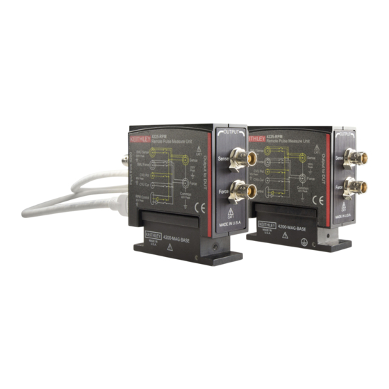
Model 4200A-SCS Pulse Card (PGU and PMU) User's Manual Section 2: Connections Model 4225-RPM The 4225-RPM is a remote amplifier/switch that is used as a current preamplifier for the 4225-PMU. The RPM provides additional high-speed, low-current measurement ranges. The RPM can also be used as a switch for the 4200-SMU, 4201-SMU, 4210-CVU, and 4215-CVU. Using the RPM as a switch (on page 2-9). -
Page 17: Connecting The Rpm To The Pmu
Section 2: Connections Model 4200A-SCS Pulse Card (PGU and PMU) User's Manual RPM wiring diagram The internal wiring diagram of the RPM is shown in the following figure. Signals from the 4200A-SCS instrument cards are routed through the RPM to the output Force and Sense connectors. - Page 18 Model 4200A-SCS Pulse Card (PGU and PMU) User's Manual Section 2: Connections The RPM is matched to a PMU card and channel. Make sure to connect the RPM only to that PMU card and channel. Labels on top of the RPM indicate the specific connection channel and PMU. For example, "PMU1-2"...
-
Page 19: Mounting The Rpm
Section 2: Connections Model 4200A-SCS Pulse Card (PGU and PMU) User's Manual Mounting the RPM When mounting the 4225-RPM, make sure that there is a minimum of 5 cm (2 in.) of space between multiple RPM base assemblies. Spacing multiple 4225-RPM or 4200-PA instruments closer than 5 cm (2 in.) from the 4200-MAG-BASE can cause the internal relays to malfunction. -
Page 20: Using The Rpm As A Switch
Model 4200A-SCS Pulse Card (PGU and PMU) User's Manual Section 2: Connections Using the RPM as a switch You can use the RPM to switch a PMU, CVU, or SMU to a DUT terminal. The RPM wiring diagram (on page 2-6) figure shows the switches. The following figure shows a typical test configuration for using an RPM as a switch for a PMU, SMU, and CVU. -
Page 21: Two-Terminal Device Connections
Section 2: Connections Model 4200A-SCS Pulse Card (PGU and PMU) User's Manual Two-terminal device connections The following figure shows connections to a two-terminal device using a single channel. Connect one end of the device to the center conductor of Ch 1 and connect the other side to pulse card common (outside shield of the SMA cable). - Page 22 Model 4200A-SCS Pulse Card (PGU and PMU) User's Manual Section 2: Connections You can also connect a two-terminal device to the two channels of a PMU, as shown in the following figure. In this case, channel 1 will source/pulse voltage, and channel 2 will measure the resulting current.
-
Page 23: Three-Terminal Device Connections
Section 2: Connections Model 4200A-SCS Pulse Card (PGU and PMU) User's Manual Three-terminal device connections A three-terminal device can be connected using either two or three PMU channels, depending on if source and/or measuring must be performed at each device pin. An example of both channels of a single PMU connected to a three-terminal MOSFET is shown in the following figure. -
Page 24: Four-Terminal Device Connections
Model 4200A-SCS Pulse Card (PGU and PMU) User's Manual Section 2: Connections Four-terminal device connections To test a four-terminal device, two PMUs are usually required. The following figure shows the four PMU channels connected to a four-terminal MOSFET. This configuration enables you to have complete flexibility to enable pulsing and measuring at any terminal on the device. - Page 25 Section 2: Connections Model 4200A-SCS Pulse Card (PGU and PMU) User's Manual The following illustrates the connection to a 4-terminal device using the cabling and adapters that are included with either RPM or the 4225-PMU. Figure 14: RPM output connection to 4-terminal device 2-14 4200A-PMU-900-01 Rev.
-
Page 26: Pulse Source-Measure Connections
Model 4200A-SCS Pulse Card (PGU and PMU) User's Manual Section 2: Connections Pulse source-measure connections TRIGGER OUT of a pulse generator card can be connected to TRIGGER IN of other pulse generator cards to synchronize the start of pulse outputs. For details on using the trigger connectors, refer to Triggering (on page 4-22). -
Page 27: Using An Adapter Cable To Connect Pulse Card To Dut
Section 2: Connections Model 4200A-SCS Pulse Card (PGU and PMU) User's Manual Using an adapter cable to connect pulse card to DUT The following figure shows an example of how to make pulse card connections to the device under test (DUT) using the supplied SMA to SSMC adapter cable. Figure 16: Pulse card connections using the SMA to dual SSMC adapter cable White SMA cable (2 m (6.5 ft), included with the PGU and PMU) SMA to SSMC Adapter Cable (4200-PRB-C, included with the PGU and PMU) -
Page 28: Rpm Connections To Dut
Model 4200A-SCS Pulse Card (PGU and PMU) User's Manual Section 2: Connections Figure 17: Pulse card connections to triaxial prober or test fixture White SMA cable (2 m (6.5 ft) included with the PGU or PMU) SMA socket to BNC plug (included with the 4200-PMU-Prober-Kit) BNC socket to three-lug triaxial plug (included with the 4200-PMU-Prober-Kit) RPM connections to DUT With an RPM installed, never make connections directly to any of the SMA connectors (CH1... -
Page 29: Remote Sensing Using Rpm Connections To A Prober
Section 2: Connections Model 4200A-SCS Pulse Card (PGU and PMU) User's Manual Figure 18: Two-terminal local sense connections using the SMA to SSMC adapter cable This connection method eliminates the triaxial guard (inner shield). Triaxial plug to BNC socket adapter (supplied with the RPM) BNC plug to SMA socket adapter (supplied with the RPM) White SMA cable, 20.32 cm (8 in.) (supplied with the RPM) SMA to SSMC adapter cable (4200-PRB-C, supplied with the PMU) - Page 30 Model 4200A-SCS Pulse Card (PGU and PMU) User's Manual Section 2: Connections Figure 19: RPM connections to a prober Triaxial plug-to-BNC socket adapter (supplied with the RPM) BNC plug-to-SMA socket adapter (supplied with the RPM) White SMA cable (20.32 cm (8 in.), supplied with the RPM) SMA-to-SSMC Adapter Cable (4200-PRB-C, supplied with the PMU) For details on using these prober cable kits, refer to PA-1000 for the Suss prober, PA-1001 for the Cascade prober, PA-1080 for the Lucas Signatone prober, and PA-1085 for the Wentworth prober.
-
Page 31: Pmu Connection Compensation
Section 2: Connections Model 4200A-SCS Pulse Card (PGU and PMU) User's Manual PMU connection compensation You can correct errors caused by connections and cable length between the 4225-PMU and the device under test (DUT) by using connection compensation. When connection compensation is enabled, the default or measured compensation values are factored into each DUT measurement. -
Page 32: Offset Current Compensation
Model 4200A-SCS Pulse Card (PGU and PMU) User's Manual Section 2: Connections Offset current compensation Error currents can be introduced into your pulsed measurements setup by PMUs. PMU offset compensation reduces error currents by subtracting measurements taken at 0 V from all subsequent readings. -
Page 33: Enabling Connection Compensation
Section 2: Connections Model 4200A-SCS Pulse Card (PGU and PMU) User's Manual Figure 21: PMU Connection Compensation dialog 4. To perform short connection compensation, select Measure Short, then follow the on-screen instructions or replace the DUT in the test fixture with a short. 5. - Page 34 Model 4200A-SCS Pulse Card (PGU and PMU) User's Manual Section 2: Connections To enable connection compensation: 1. Select the test. 2. Select Configure. 3. Select the terminal to be compensated. 4. In the right pane, select Terminal Settings. 5. Select Advanced. The PMU Advanced Terminal Settings dialog is displayed. 6.
-
Page 35: Load-Line Effect Compensation (Llec) For The Pmu
Section 2: Connections Model 4200A-SCS Pulse Card (PGU and PMU) User's Manual Load-line effect compensation (LLEC) for the PMU Load-line effect compensation (LLEC) is only performed for standard pulse I-V testing using PMU measure ranges. It is not performed when using 4225-RPM measure ranges (≤10 μA). The active RPM circuitry provides its own analog LLEC (assuming there is a short cable from the RPM to the DUT). -
Page 36: Methods To Compensate For Load-Line Effect
Model 4200A-SCS Pulse Card (PGU and PMU) User's Manual Section 2: Connections Methods to compensate for load-line effect The methods to compensate for load-line effect include: • Use the built-in load-line effect compensation (LLEC) in the PMU for the standard 2-level pulse mode. - Page 37 Section 2: Connections Model 4200A-SCS Pulse Card (PGU and PMU) User's Manual Figure 23: LLEC algorithm for two-level pulsing (PMU) There are two parameters that control how the LLEC algorithm functions: Maximum number of iterations and tolerance window. For ITMs, the maximum number of iterations is fixed at 20 and the tolerance window is 0.3 percent.
-
Page 38: Coping With The Load-Line Effect
Model 4200A-SCS Pulse Card (PGU and PMU) User's Manual Section 2: Connections Coping with the load-line effect There are several ways of working with this effect. The simplest one is to program the DUT load into the pulse card channel using the pulse_load function, or setting the Pulse Load value in the KPulse (on page 5-1) virtual front panel. -
Page 39: Test Considerations
Section 2: Connections Model 4200A-SCS Pulse Card (PGU and PMU) User's Manual Figure 24: Load-line effect on FET family of curves The same sweep is used to generate the green curves (LLEC off). The best green curve is the one at the bottom (bias V = 2.5 V). -
Page 40: Lpt Functions Used To Configure Llec
Model 4200A-SCS Pulse Card (PGU and PMU) User's Manual Section 2: Connections Figure 25: Curve showing poor LLEC compensation LPT functions used to configure LLEC • The LPT functions used to configure LLEC for the PMU are: • pulse_load: Use this function to set the output impedance for the DUT when LLEC is disabled. Setting the DUT resistance is useful when the DUT resistance is known and is relatively constant •... -
Page 41: Disable Llec And Set The Output Impedance
Section 2: Connections Model 4200A-SCS Pulse Card (PGU and PMU) User's Manual Figure 26: Enabling LLEC Disable LLEC and set the output impedance These options are available for ITMs. With LLEC disabled, you can input the known resistance of the DUT. The resistance value is then used in a compensation process to output the voltage. -
Page 42: Setting Up Pmus And Pgus In Clarius
Section 3 Setting up PMUs and PGUs in Clarius In this section: Introduction ................3-1 Configure the PGU, PMU, and RPM using tests ...... 3-1 Create a PMU project ............... 3-2 Configure the tests ..............3-3 PMU operation modes ............. 3-5 PMU - all terminal parameters .......... -
Page 43: Create A Pmu Project
Section 3: Setting up PMUs and PGUs in Clarius Model 4200A-SCS Pulse Card (PGU and PMU) User's Manual Create a PMU project To create a new project: 1. Select Save to save your existing project. 2. Choose Select. 3. Select the Projects tab. 4. -
Page 44: Configure The Tests
Model 4200A-SCS Pulse Card (PGU and PMU) User's Manual Section 3: Setting up PMUs and PGUs in Clarius Configure the tests To configure a test: 1. Select Configure. Figure 28: Configure highlighted 2. From the Key Parameters pane, adjust the pulse voltage sweep levels of PMU1-2 on the Drain terminal and the Pulse Step Voltage of PMU1-1 on the Gate terminal, as needed. - Page 45 Section 3: Setting up PMUs and PGUs in Clarius Model 4200A-SCS Pulse Card (PGU and PMU) User's Manual 3. From the Test Settings pane and Advanced Test Settings dialog, adjust the Pulse Settings and Timing Parameters as needed. Figure 30: Test Settings pane and Test Settings Advanced dialog 4.
-
Page 46: Pmu Operation Modes
Model 4200A-SCS Pulse Card (PGU and PMU) User's Manual Section 3: Setting up PMUs and PGUs in Clarius PMU operation modes The operation mode determines what type of test is run on the terminal. Selecting the appropriate mode simplifies configuration options. A Pulse Sweep and Pulse Step function are identical. -
Page 47: Pmu - All Terminal Parameters
Section 3: Setting up PMUs and PGUs in Clarius Model 4200A-SCS Pulse Card (PGU and PMU) User's Manual Figure 33: Pulse train When DC Bias operation mode is selected, the PMU outputs the dc base voltage. The following figure shows a representation of a dc voltage waveform. Figure 34: DC Bias waveform The terminal settings available for each operation mode are described in the following topics. -
Page 48: Step (Pulse Amplitude Sweep)
Model 4200A-SCS Pulse Card (PGU and PMU) User's Manual Section 3: Setting up PMUs and PGUs in Clarius Step (Pulse Amplitude Sweep) The voltage size of each step of the sweep. The source level changes in equal steps of this size from the start level to the stop level. -
Page 49: Dual Sweep (Pulse)
Section 3: Setting up PMUs and PGUs in Clarius Model 4200A-SCS Pulse Card (PGU and PMU) User's Manual Dual Sweep (pulse) When you select Dual Sweep, the instrument sweeps from start to stop, then from stop to start. When you clear Dual Sweep, the instrument sweeps from start to stop only. The amplitude, base, and dc sweeps have an option for Dual Sweep. -
Page 50: Current Spot Mean High
Model 4200A-SCS Pulse Card (PGU and PMU) User's Manual Section 3: Setting up PMUs and PGUs in Clarius Current Spot Mean High Makes current measurements on the amplitude. Available when the Test Mode is set to Pulse I-V. The following figure shows an example of a spot mean measurement on pulse high (amplitude) and pulse low (base level). -
Page 51: Low Range
Section 3: Setting up PMUs and PGUs in Clarius Model 4200A-SCS Pulse Card (PGU and PMU) User's Manual Fixed current measurement ranges (PMU only) 10 V range 40 V range 100 μA 10 mA 200 mA 10 mA − 800 mA If you are using an RPM, additional current measurement ranges become available to the PMU. -
Page 52: Voltage Spot Mean High
Model 4200A-SCS Pulse Card (PGU and PMU) User's Manual Section 3: Setting up PMUs and PGUs in Clarius Voltage Spot Mean High Makes voltage measurements on the amplitude. Available when the Test Mode is set to Pulse IV. The following figure shows an example of a spot mean measurement on pulse high (amplitude) and pulse low (base level). -
Page 53: Report Status (Pmu)
Section 3: Setting up PMUs and PGUs in Clarius Model 4200A-SCS Pulse Card (PGU and PMU) User's Manual Report Status (PMU) When this option is selected, Clarius records measurement status information when the test executes. A column of the Analyze spreadsheet displays this information. Hover over a cell to review the information. - Page 54 Model 4200A-SCS Pulse Card (PGU and PMU) User's Manual Section 3: Setting up PMUs and PGUs in Clarius Figure 41: Status tab showing faults Status codes Each measurement includes an 8-digit status code. Assign the following letters to the code and use the following table to determine status: A B C D E F G H In the figure shown in...
- Page 55 Section 3: Setting up PMUs and PGUs in Clarius Model 4200A-SCS Pulse Card (PGU and PMU) User's Manual PMU measurement status codes Code Summary or description Value letter Load-line effect compensation (LLEC) and 0 = LLEC disabled, sweep not skipped sweep 1 = LLEC failed, sweep not skipped 3 = LLEC successful, sweep not skipped...
-
Page 56: Compensation Short Connection
Model 4200A-SCS Pulse Card (PGU and PMU) User's Manual Section 3: Setting up PMUs and PGUs in Clarius Compensation Short Connection Use to enable or disable short connection compensation. Refer to PMU connection compensation page 2-20) for detail on setting up and using connection compensation. Load Line Effect Compensation Use to enable or disable load-line effect compensation (LLEC). -
Page 57: Threshold Voltage
Section 3: Setting up PMUs and PGUs in Clarius Model 4200A-SCS Pulse Card (PGU and PMU) User's Manual Threshold Voltage The voltage threshold allows you to set a voltage threshold. If the threshold is reached or exceeded, the present sweep is stopped. Testing continues with any subsequent sweeps. This threshold is a comparison of the measurement after the pulse has been applied to the DUT (the threshold value will be exceeded, at least slightly). - Page 58 Model 4200A-SCS Pulse Card (PGU and PMU) User's Manual Section 3: Setting up PMUs and PGUs in Clarius For pulse I-V, spot mean measurements are made on pulse amplitude and base level. You can measure voltage and current. The following figure shows the measure windows for spot mean measurements.
- Page 59 Section 3: Setting up PMUs and PGUs in Clarius Model 4200A-SCS Pulse Card (PGU and PMU) User's Manual For UTMs, the pulse_meas_timing function allows you to adjust the measure window for the pulse I-V test mode or the pre-data and post-data settings for the waveform measurements. For ITMs, the measure window and pre-data and post-data settings are fixed.
- Page 60 Model 4200A-SCS Pulse Card (PGU and PMU) User's Manual Section 3: Setting up PMUs and PGUs in Clarius Figure 45: Pulse IV - Discrete pulses Waveform Capture (Discrete Pulses) measurement example For the example shown in the following figure, the samples of three pulses are captured. The 51 samples (17 samples x 3 pulses) are placed in the Analyze sheet.
-
Page 61: Timing Parameters
Section 3: Setting up PMUs and PGUs in Clarius Model 4200A-SCS Pulse Card (PGU and PMU) User's Manual Number of Pulses The number of pulses for the PMU channel to output and measure for each step in the sweep (1 to 10,000). - Page 62 Model 4200A-SCS Pulse Card (PGU and PMU) User's Manual Section 3: Setting up PMUs and PGUs in Clarius Period The pulse period is the time interval between the start of the rising transition edge of consecutive output pulses, as shown in the following figure. To minimize self-heating effects, set a pulse period that is 10 to 100 times longer than the pulse width to produce a duty cycle that is 1 percent to 10 percent.
-
Page 63: Pmu Advanced Test Settings
Section 3: Setting up PMUs and PGUs in Clarius Model 4200A-SCS Pulse Card (PGU and PMU) User's Manual Pulse Delay The pulse delay is the time interval between the start of the rising pulse edge of the trigger output pulse and the output pulse. You can set the rising or falling polarity of the trigger output pulse edge to the output pulse. - Page 64 Model 4200A-SCS Pulse Card (PGU and PMU) User's Manual Section 3: Setting up PMUs and PGUs in Clarius Settling Times The settling time is the time that it takes for pulse levels to stabilize after the voltage or current is changed, such as during execution of a sweep.
- Page 65 Section 3: Setting up PMUs and PGUs in Clarius Model 4200A-SCS Pulse Card (PGU and PMU) User's Manual Settling time is measured from the 90 percent point on the rising edge to the point where the pulse level remains in the accuracy band, as shown in the following figure. Figure 52: Settling time PMU minimum settling times versus current measure range The PMU and RPM current measure ranges require time to reach a settled value.
- Page 66 Model 4200A-SCS Pulse Card (PGU and PMU) User's Manual Section 3: Setting up PMUs and PGUs in Clarius You can override the settled measurement requirement for the PMU or PMU+RPM measurements. In the Clarius My Settings, Environment Settings, select PMU: Allow unsettled measurements. The following figure contains a graph of the current signal settling time of three current measure ranges of the 4225-RPM.
- Page 67 Section 3: Setting up PMUs and PGUs in Clarius Model 4200A-SCS Pulse Card (PGU and PMU) User's Manual Figure 54: Timing button (PDU Definition tab) An example is shown in the following figure. Figure 55: Pulse Timing Preview example 3-26 4200A-PMU-900-01 Rev.
- Page 68 Model 4200A-SCS Pulse Card (PGU and PMU) User's Manual Section 3: Setting up PMUs and PGUs in Clarius The preview displays representations of the waveforms for the different PMU channels in the test. The illustrated pulse waveforms are defined by the Pulse Timing settings for the specific PMU. This preview provides a representation of parameter values (no signals are output to the test device).
- Page 69 Section 3: Setting up PMUs and PGUs in Clarius Model 4200A-SCS Pulse Card (PGU and PMU) User's Manual shown in the bottom graph of the following figure as six pulse periods. In this example, the pulse periods have voltage amplitude increasing from 0 V to 5 V. The graph labeled “Expanded View”...
- Page 70 Model 4200A-SCS Pulse Card (PGU and PMU) User's Manual Section 3: Setting up PMUs and PGUs in Clarius PMU1-2 sweeps 0 V through 4 V in 0.5 V increments. The stepping channel is performing pulse amplitude steps with four step points. On the outer loop, PMU1-1 pulses the four steps of 1 V through 2.5 V in 0.5 V increments.
- Page 71 Section 3: Setting up PMUs and PGUs in Clarius Model 4200A-SCS Pulse Card (PGU and PMU) User's Manual If you change the number of pulses to three (instead of one) and only display one channel (PMU1-1, instead of Show All), the preview of the waveform changes as shown in the following figure. Each point in the step now uses three periods, so there are three pulses shown in the Expanded View.
- Page 72 Model 4200A-SCS Pulse Card (PGU and PMU) User's Manual Section 3: Setting up PMUs and PGUs in Clarius step test with the number of pulses set to three. Note that the value for the number of pulses does not affect the number of sweep or step points in the test. Figure 60: Two-channel test with three points (PMU1-1 and PMU1-2 displayed) Higher channel count test example This example shows how to use the Pulse Timing Preview for higher channel count tests.
- Page 73 Section 3: Setting up PMUs and PGUs in Clarius Model 4200A-SCS Pulse Card (PGU and PMU) User's Manual The following figure uses the key test parameters shown in the following table. Operation mode and voltages for the four channels PMU1-1 PMU1-2 PMU2-1 PMU2-2...
- Page 74 Model 4200A-SCS Pulse Card (PGU and PMU) User's Manual Section 3: Setting up PMUs and PGUs in Clarius Figure 62: Zooming (Expanded View graph) Scrolling the magnified area To move the viewable area of the graph after you zoom in on a graph, hold down Shift while dragging the mouse.
- Page 75 Section 3: Setting up PMUs and PGUs in Clarius Model 4200A-SCS Pulse Card (PGU and PMU) User's Manual Select Shift+click and move or scroll a magnified graph by moving the mouse. Figure 63: Scroll (or move) a magnified entire test graph Errors If either graph is not updating as expected, select Refresh to zoom out and redraw both graphs.
-
Page 76: Pmu Capacitive Charging/Discharging Effects
Model 4200A-SCS Pulse Card (PGU and PMU) User's Manual Section 3: Setting up PMUs and PGUs in Clarius PMU capacitive charging/discharging effects During pulse transitions, the measured current charges and discharges the capacitance in the system (see following figure, red waveform). This system capacitance consists of the cable capacitance, PMU (with RPM, if connected) capacitance, and device capacitance. - Page 77 Section 3: Setting up PMUs and PGUs in Clarius Model 4200A-SCS Pulse Card (PGU and PMU) User's Manual The equation shows that this effect is a function of the capacitance, as well as the dV/dt. Therefore, minimizing the capacitance will reduce this measurement artifact. The cabling is typically the largest contributor to the system capacitance.
-
Page 78: Pmu And Rpm Measure Ranges Are Not Source Ranges
Model 4200A-SCS Pulse Card (PGU and PMU) User's Manual Section 3: Setting up PMUs and PGUs in Clarius Figure 67: Setup for low-side measurement In the previous figure, the voltage pulse is applied by channel 1; channel 2 does not pulse. Therefore, there is no dV/dt, and therefore there are no charging or discharging currents during the pulse transition. -
Page 79: 4220-Pgu And 4225-Pmu Output Limitations
Section 3: Setting up PMUs and PGUs in Clarius Model 4200A-SCS Pulse Card (PGU and PMU) User's Manual Since the interconnect and the DUT always have some capacitance, it is best to charge up this capacitance as quickly as possible. This can be done by allowing the maximum amount of current to flow into the capacitor during charging. -
Page 80: Step Or Sweep Multiple Device Terminals In The Same Test
Model 4200A-SCS Pulse Card (PGU and PMU) User's Manual Section 3: Setting up PMUs and PGUs in Clarius Step or sweep multiple device terminals in the same test Multiple steps or sweeps in an interactive test module (ITM) must track with regard to step number and duration. - Page 81 Section 3: Setting up PMUs and PGUs in Clarius Model 4200A-SCS Pulse Card (PGU and PMU) User's Manual In the following figure, the step width and number of steps of the subordinate list sweep tracks the step width and the number of steps of the master list sweep. Figure 70: Master list sweeps versus subordinate list sweeps If you do not specify an instrument to be the master, the first instrument that was assigned to the step or sweep operation mode is assigned to be the master.
-
Page 82: Basic Troubleshooting Procedure
Model 4200A-SCS Pulse Card (PGU and PMU) User's Manual Section 3: Setting up PMUs and PGUs in Clarius When a master is set, Clarius sets the points and step size values for the subordinate terminal to be the same as the settings for the master terminal. You cannot change the subordinate points value for the subordinate terminal. -
Page 83: Step 2. Verify The Pulse Shape
Section 3: Setting up PMUs and PGUs in Clarius Model 4200A-SCS Pulse Card (PGU and PMU) User's Manual Step 2. Verify the pulse shape To check that the pulse shape provides a flat, settled portion near the end of the pulse top: 1. -
Page 84: Step 3. Is The Pulse Level Correct For Each Channel
Model 4200A-SCS Pulse Card (PGU and PMU) User's Manual Section 3: Setting up PMUs and PGUs in Clarius Step 3. Is the pulse level correct for each channel? 1. If the pulse level is not correct for each channel, enable load-line effect compensation (LLEC). To compensate for the IR drop effect, the LLEC algorithm applies multiple pulses at each sweep step;... - Page 85 Section 3: Setting up PMUs and PGUs in Clarius Model 4200A-SCS Pulse Card (PGU and PMU) User's Manual Figure 71: PMU IV sweep All Parameters thresholds 4. Enter the maximum power for the test device. An example of a transistor test with LLEC disabled with a power threshold of 3 W and a voltage threshold of 12 V is shown in the following figure.
- Page 86 Model 4200A-SCS Pulse Card (PGU and PMU) User's Manual Section 3: Setting up PMUs and PGUs in Clarius The following figure shows a family of curves from a fairly high-powered device with the load-line effect. The following figure shows the same device tested with load-line effect compensation enabled. With LLEC enabled, the curves stop at the programmed V = 12 V.
- Page 87 Section 3: Setting up PMUs and PGUs in Clarius Model 4200A-SCS Pulse Card (PGU and PMU) User's Manual Figure 73: Vd-Id family of curves with LLEC enabled (every curve finishes at Vd = 12 V) For user test modules (UTMs), although the process described above applies, there are a few differences.
- Page 88 Model 4200A-SCS Pulse Card (PGU and PMU) User's Manual Section 3: Setting up PMUs and PGUs in Clarius Figure 74: PMU IV sweep Help pane description This user module allows for an optional SMU to dc bias a transistor bulk while performing a pulse I-V sweep with a 4225-PMU and optional 4225-RPM.
- Page 89 Section 3: Setting up PMUs and PGUs in Clarius Model 4200A-SCS Pulse Card (PGU and PMU) User's Manual Figure 75: PMU IV sweep Return Values It may also be necessary to research further using additional error codes. Three-digit negative error codes are most likely LPT-command error codes.
-
Page 90: Pulse Card Concepts
Section 4 Pulse card concepts In this section: Models 4220-PGU and 4225-PMU ........... 4-1 4200A-SCS power supply limitations ........4-5 Pulse source-measure concepts ..........4-8 Measurement types ..............4-25 Models 4220-PGU and 4225-PMU The 4220-PGU High Voltage Pulse Generator Unit and 4225-PMU Ultra-Fast Pulse Measure Unit are high-speed pulse-generator cards for the 4200A-SCS. -
Page 91: Pmu Block Diagram
Section 4: Pulse card concepts Model 4200A-SCS Pulse Card (PGU and PMU) User's Manual The simplified circuits of the 4220-PGU and 4225-PMU pulse generators are shown in the following figure. Figure 76: Simplified circuits of the PGU and PMU PMU block diagram The following figure shows the block diagram of the PMU. -
Page 92: Pulse Modes
Model 4200A-SCS Pulse Card (PGU and PMU) User's Manual Section 4: Pulse card concepts Pulse modes The PGU and PMU support the following pulse modes: • Standard pulse mode: For this two-level pulse mode, the user defines a high and low level for the pulse output. -
Page 93: Measure Modes
Section 4: Pulse card concepts Model 4200A-SCS Pulse Card (PGU and PMU) User's Manual Measure modes The measure modes for the PMU are discrete pulses and average pulses. Discrete pulses For pulse I-V (spot mean), the averaged voltage or current readings for every sampled pulse period are acquired. -
Page 94: 4200A-Scs Power Supply Limitations
Model 4200A-SCS Pulse Card (PGU and PMU) User's Manual Section 4: Pulse card concepts 4200A-SCS power supply limitations In some system configurations, the 4200A-SCS power supply cannot supply enough current if a test has too many high-power instruments enabled. Some system configurations may have enough instruments installed to exceed the power supply limit if the selected test has too many channels enabled. - Page 95 Section 4: Pulse card concepts Model 4200A-SCS Pulse Card (PGU and PMU) User's Manual Equations to calculate power: PowerIDLE = [(29.4 * nPGU) + (50.4 * nPMU) + (4.2 * nRPM)] PowerTEST = [(45 * nHPSMU) + (8.4 * nC10) + (54.6 * nC40)] PowerTOTAL = PowerIDLE + PowerTEST PowerTOTAL = 500 maximum.
- Page 96 Model 4200A-SCS Pulse Card (PGU and PMU) User's Manual Section 4: Pulse card concepts 4200A-SCS power requirements for valid combinations of internal system instruments Idle power Power used in test nPMU nRPM nC10 nC40 nHPSMU PowerIDLE PowerTEST PowerTOTAL 117.6 218.4 117.6 263.4 117.6...
-
Page 97: Pulse Source-Measure Concepts
Section 4: Pulse card concepts Model 4200A-SCS Pulse Card (PGU and PMU) User's Manual Pulse source-measure concepts Ultra-fast I-V sourcing and measurement have become increasingly important capabilities for many technologies, including compound semiconductors, medium-power devices, nonvolatile memory, microelectromechanical systems (MEMs), nanodevices, solar cells, and CMOS devices. Using pulsed I-V signals to characterize devices rather than DC signals makes it possible to study or reduce the effects of self-heating (joule heating) or to minimize current drift or degradation in measurements due to trapped charge. - Page 98 Model 4200A-SCS Pulse Card (PGU and PMU) User's Manual Section 4: Pulse card concepts Figure 79: Pulsed I-V tests Transient I-V tests Transient I-V, or waveform capture, is a time-based current or voltage measurement that is typically the capture of a pulsed waveform. A transient test is typically a single pulse waveform that is used to study time-varying parameters, such as the drain current degradation versus time due to charge trapping or self-heating.
-
Page 99: Sample Rate
Section 4: Pulse card concepts Model 4200A-SCS Pulse Card (PGU and PMU) User's Manual Pulsed sourcing tests Pulsed sourcing can involve any of the following: • Outputting user-defined two-level pulses. • Outputting multi-level pulses using the built-in Segment Arb ® function. -
Page 100: Segment Arb Waveform
Model 4200A-SCS Pulse Card (PGU and PMU) User's Manual Section 4: Pulse card concepts Pulse I-V (spot mean) The maximum number of samples per A/D per test is <1,000,000 (one million). If an ITM is configured to yield more than one million samples, Clarius automatically lowers the sampling rate. For pulse I-V (spot mean), typically the sample rate is reduced only if the measure window is wide (due to a wide pulse width or period) or if the number of pulses is large. - Page 101 Section 4: Pulse card concepts Model 4200A-SCS Pulse Card (PGU and PMU) User's Manual Figure 82: Example of waveform measured using seg_arb_sequence Two types of measurements are supported: spot mean and sample. Spot mean measurements take a mean of all the samples within the measured window and result in a single reading for that segment. The sample measurement reports all of the samples within the measurement window, which can then be plotted versus time to provide a waveform.
- Page 102 Model 4200A-SCS Pulse Card (PGU and PMU) User's Manual Section 4: Pulse card concepts Figure 83: Two sequence definitions A definition showing two sequences with looping is illustrated in the following figure. 4200A-PMU-900-01 Rev. B March 2023 4-13...
- Page 103 Section 4: Pulse card concepts Model 4200A-SCS Pulse Card (PGU and PMU) User's Manual Figure 84: Definition showing two sequences with looping The graph of the measurement of a two-sequence Segment Arb with looping, from UTM pmu-segarb-complete in the pmu-dut-examples project, is shown in the following figure. Figure 85: Graph of the waveform (two-sequence with looping) measurement Pulse modes: Source, Segment Arb 4-14...
- Page 104 Model 4200A-SCS Pulse Card (PGU and PMU) User's Manual Section 4: Pulse card concepts LPT function: seg_arb_define This function is used to define a Segment Arb waveform. This function includes parameters to specify the number of segments (nSegments) and arrays for start (startvals), stop (stopvals), and time values (timevals).
-
Page 105: Pulse Waveforms For Nonvolatile Memory Testing
Section 4: Pulse card concepts Model 4200A-SCS Pulse Card (PGU and PMU) User's Manual KPulse full arb waveforms The Keithley Pulse tool (KPulse) is a software application used to control the optional pulse generator cards. KPulse can be used to create, save, and output full arb waveforms. It also provides a collection of basic full arb waveform types such as sine, square, triangle, noise, Gaussian, and calculation. -
Page 106: Waveform Capture
Model 4200A-SCS Pulse Card (PGU and PMU) User's Manual Section 4: Pulse card concepts Waveform capture The maximum number of rows that can appear in the Analyze sheet for an ITM is 4096. Each waveform sample uses one row of the sheet. Therefore, the number of samples acquired for a waveform must fit within the 4096 points. - Page 107 Section 4: Pulse card concepts Model 4200A-SCS Pulse Card (PGU and PMU) User's Manual The 50 Ω output resistance of the pulse channel and the DUT resistance effectively make a voltage divider. Ohm’s law is the only concept required to determine I and V in this simple nondynamic approach.
- Page 108 Model 4200A-SCS Pulse Card (PGU and PMU) User's Manual Section 4: Pulse card concepts Example 2: High resistance DUT A high resistance DUT is shown in the following figure. 1 MΩ Pulse V high Pulse V 50 Ω Pulse load Figure 89: 5 V pulse into a 1 MΩ...
- Page 109 Section 4: Pulse card concepts Model 4200A-SCS Pulse Card (PGU and PMU) User's Manual Example 3: Low resistance DUT A low resistance DUT is shown in the following figure. 5 Ω Pulse V HIGH Pulse V 50 Ω Pulse load Figure 90: 5 V pulse into a 5 Ω...
- Page 110 Model 4200A-SCS Pulse Card (PGU and PMU) User's Manual Section 4: Pulse card concepts Example 4: Maximum voltage and current, high speed range V = I * R = 10 V for high speed range = 5 Ω / (R TOTAL pulse generator = 10 V / (50 Ω...
-
Page 111: Triggering
Section 4: Pulse card concepts Model 4200A-SCS Pulse Card (PGU and PMU) User's Manual Test device resistance (Ω) Voltage (V)* Current (A)* 0.196 0.196 0.909 0.182 1.667 0.167 3.333 0.133 0.100 6.667 0.067 8.333 0.033 9.524 0.0095 10 k 9.950 0.000995 * Approximate value;... - Page 112 Model 4200A-SCS Pulse Card (PGU and PMU) User's Manual Section 4: Pulse card concepts If you need to define a trigger in using a source-only pulse waveform (2-level or Segment Arb), you can create a user test module (UTM) that uses the pulse source only (PG2) command set. This allows an external trigger (LPT command pulse_trig_source) to output a 2-level pulse (LPT commands pulse_vhigh and pulse_vlow) or segment arb waveforms (LPT command seg_arb_define).
- Page 113 Section 4: Pulse card concepts Model 4200A-SCS Pulse Card (PGU and PMU) User's Manual Example LPT function sequence: Basic triggering The following LPT function sequence uses the software trigger to initiate a 3-pulse burst for both channels, where both the pulse and trigger output three pulses. // Stop pulse generator output: pulse_halt(VPU1);...
-
Page 114: Measurement Types
Model 4200A-SCS Pulse Card (PGU and PMU) User's Manual Section 4: Pulse card concepts Example LPT function sequence: pulse-measure synchronization The following LPT function sequence uses the software trigger to initiate a 3-pulse burst for CHANNEL 1. The three output pulses trigger the scope to perform three measurements. It assumes the scope is configured to trigger on leading edge triggers from the pulse generator. -
Page 115: Spot Mean Measurements
Section 4: Pulse card concepts Model 4200A-SCS Pulse Card (PGU and PMU) User's Manual Spot mean measurements Spot mean measurements sample a portion of the amplitude and a portion of the base level (see Spot mean measurement timing (on page 4-30)). The portions to be sampled are specified as a percentage. -
Page 116: Spot Mean Average Readings
Model 4200A-SCS Pulse Card (PGU and PMU) User's Manual Section 4: Pulse card concepts Spot mean average readings For this data acquisition type, each returned reading is a mean-of-the-means. Spot mean average averages the mean readings for all the pulses in the burst. In the figure in Spot mean discrete readings (on page 4-26), each mean reading for pulse 1 is averaged with each corresponding mean... -
Page 117: Waveform Discrete Readings
Section 4: Pulse card concepts Model 4200A-SCS Pulse Card (PGU and PMU) User's Manual Figure 94: Waveform measurements A waveform measurement can include pre-data and post-data. Pre-data is extra data taken before the rise time of the pulse; post-data is extra data taken after the fall time (see figure below). See Waveform measurement timing (on page 4-30) for details on measurement timing for pre-data and post-data. -
Page 118: Waveform Average Readings
Model 4200A-SCS Pulse Card (PGU and PMU) User's Manual Section 4: Pulse card concepts Figure 96: Returned data set for waveform discrete readings Waveform average readings For this data acquisition type, each returned reading is a mean average of the corresponding samples for all the pulses in the burst. -
Page 119: Measurement Timing
Section 4: Pulse card concepts Model 4200A-SCS Pulse Card (PGU and PMU) User's Manual Measurement timing Use the pulse_meas_timing function to configure pulse measurement timing. Spot mean measurement timing The spot mean measurement type samples a portion of the amplitude and a portion of the base level. The measured samples are then averaged to yield a single voltage and current reading for the amplitude and base low levels. - Page 120 Model 4200A-SCS Pulse Card (PGU and PMU) User's Manual Section 4: Pulse card concepts A waveform measurement can include pre-data and post-data. Pre-data is extra data taken before the rise time of the pulse; post-data is extra data taken after the fall time. Waveform measurements (on page 4-27) shows an example where 10% (0.1) pre-data and 10% (0.1) post-data is taken.
- Page 121 Section 4: Pulse card concepts Model 4200A-SCS Pulse Card (PGU and PMU) User's Manual Example: pulse_meas_wfm This function sets channel 1 of the PMU for the waveform discrete measure type to acquire the voltage/current readings for the waveform and the time stamps. It also enables LLEC. pulse_meas_wfm(PMU1, 1, 0, 1, 1, 1, 1);...
-
Page 122: Kpulse (For Keithley Pulse Cards)
Section 5 KPulse (for Keithley Pulse Cards) In this section: Keithley Pulse Application ............5-1 Triggering ................. 5-3 Standard pulse waveforms ............5-4 Segment Arb waveforms ............5-6 Custom file arb waveforms (full arb) ......... 5-9 Keithley Pulse Application Keithley Pulse Application (KPulse) is a nonprogramming alternative that you can use to configure and control the installed Keithley pulse cards. -
Page 123: Kpulse Setup And Help
Section 5: KPulse (for Keithley Pulse Cards) Model 4200A-SCS Pulse Card (PGU and PMU) User's Manual Figure 99: KPulse GUI KPulse setup and help The KPulse menus include: • File: Use this menu to load and save KPulse setups and exit KPulse. By default, setup files are saved at the command path location: C:\s4200\kiuser\KPulse\Setup. -
Page 124: Triggering
Model 4200A-SCS Pulse Card (PGU and PMU) User's Manual Section 5: KPulse (for Keithley Pulse Cards) Trigger Master: Select the pulse card that will serve as the trigger master. Select None if you are not using a trigger master. See Triggering (on page 5-3) for more information. -
Page 125: Standard Pulse Waveforms
Section 5: KPulse (for Keithley Pulse Cards) Model 4200A-SCS Pulse Card (PGU and PMU) User's Manual Standard pulse waveforms Standard pulse waveforms are configured and controlled from the pulse card tabs in the KPulse window. The following figure explains how to use KPulse for a standard pulse output. Standard pulse waveform previewers: KPulse provides a preview of configured standard pulse waveforms for each enabled channel. - Page 126 Model 4200A-SCS Pulse Card (PGU and PMU) User's Manual Section 5: KPulse (for Keithley Pulse Cards) Set waveform, trigger, output, and general settings: 1. Select the pulse card tab (in this example, PMU1). 2. For the Waveform Type, select Pulse. 3.
-
Page 127: Segment Arb Waveforms
Section 5: KPulse (for Keithley Pulse Cards) Model 4200A-SCS Pulse Card (PGU and PMU) User's Manual Segment Arb waveforms ® Segment Arb waveforms are configured and controlled from the PGU or PMU tab in KPulse. The below figure explains how to use KPulse for segment Arb output. Due to the Segment Arb engine overhead, there is an additional 10 ns interval added to the end of the last segment of a Segment Arb waveform. - Page 128 Model 4200A-SCS Pulse Card (PGU and PMU) User's Manual Section 5: KPulse (for Keithley Pulse Cards) The output trigger levels are not shown in the waveform previewers. The following instructions describe how to use KPulse for a standard pulse output. Repeat these steps for any installed cards that you want to set to standard pulse.
-
Page 129: Exporting Segment Arb Waveform Files
Section 5: KPulse (for Keithley Pulse Cards) Model 4200A-SCS Pulse Card (PGU and PMU) User's Manual Exporting Segment Arb waveform files ® After configuring a Segment Arb waveform in KPulse, you can save it as a .ksf file. The Segment Arb .ksf files should be exported into the SarbFiles folder at the following location: C:\s4200\kiuser\KPulse\SarbFiles To export a Segment Arb waveform file:... -
Page 130: Custom File Arb Waveforms (Full Arb)
Model 4200A-SCS Pulse Card (PGU and PMU) User's Manual Section 5: KPulse (for Keithley Pulse Cards) Custom file arb waveforms (full arb) The following figure summarizes the basic processes to create a custom full arb waveform file, to load the file into a pulse card, and to output the pulse waveforms. Figure 104: Basic process to create and output custom file Arb waveforms To create custom file arb waveforms (full arb): 1. -
Page 131: Custom Arb File Operation: Select And Configure Waveforms
Section 5: KPulse (for Keithley Pulse Cards) Model 4200A-SCS Pulse Card (PGU and PMU) User's Manual Custom Arb file operation: Select and configure waveforms To select and configure waveforms: 1. Select the Arb Generator tab. 2. Select New Waveform to open the Waveform Generator dialog, shown in the following figure. Figure 105: Custom Arb file operation: Select and configure waveforms 3. -
Page 132: Custom Arb File Operation: Copy Waveforms Into Sequencer
Model 4200A-SCS Pulse Card (PGU and PMU) User's Manual Section 5: KPulse (for Keithley Pulse Cards) Custom Arb file operation: Copy waveforms into Sequencer To copy waveforms into the Sequencer: 1. Select the Arb Generator tab. 2. Select Scratch Pad or Sequencer: ... -
Page 133: Custom Arb File Operation: Load Waveform And Turn On Output
Section 5: KPulse (for Keithley Pulse Cards) Model 4200A-SCS Pulse Card (PGU and PMU) User's Manual 7. Delete buttons - After selecting a waveform in the Scratch Pad or Sequencer, select the appropriate Delete button to remove it. Note that deleting a waveform from the Scratch Pad also removes it from the Sequencer. -
Page 134: Waveform Types
Model 4200A-SCS Pulse Card (PGU and PMU) User's Manual Section 5: KPulse (for Keithley Pulse Cards) 4. Enable Channel 1 and/or Enable Channel 2. The loaded .kaf file consists of a waveform for one or both of the channels. If the .kaf file was saved with one or both channels enabled, the .kaf file loads into this tab with the same channels enabled. - Page 135 Section 5: KPulse (for Keithley Pulse Cards) Model 4200A-SCS Pulse Card (PGU and PMU) User's Manual Sine waveform An example of a sine waveform is shown in the following figure. The waveform for this example is named SINE1, but can be any name that is not already used in the Scratch Pad. After changing one or more settings, select Preview to display the waveform.
- Page 136 Model 4200A-SCS Pulse Card (PGU and PMU) User's Manual Section 5: KPulse (for Keithley Pulse Cards) Triangle waveform An example of a triangle waveform is shown in the following figure. The waveform for this example is named TRIANGLE1, but can be any name that is not already used in the Scratch Pad. After changing one or more settings, select Preview to display the waveform.
- Page 137 Section 5: KPulse (for Keithley Pulse Cards) Model 4200A-SCS Pulse Card (PGU and PMU) User's Manual Figure 111: Custom waveform Creating a file (.txt or .csv) for custom waveform The waveform file is created using a text editor, such as Notepad. To create the list of voltage points: 1.
- Page 138 Model 4200A-SCS Pulse Card (PGU and PMU) User's Manual Section 5: KPulse (for Keithley Pulse Cards) Calculation waveform An example of a calculation waveform is shown in the following figure. The waveform for this example is named CALC1, but can be any name that is not already used in the Scratch Pad. The calculation (add, subtract, multiple or divide) performs the selected math operation on two selected Scratch Pad waveforms.
- Page 139 Section 5: KPulse (for Keithley Pulse Cards) Model 4200A-SCS Pulse Card (PGU and PMU) User's Manual Figure 114: Noise waveform Gaussian waveform An example of a Gaussian waveform is shown in the following figure. The waveform for this example is named GAUSSIAN1, but can be any name that is not already used in the Scratch Pad. After changing one or more settings, select Preview to display the waveform.
- Page 140 Model 4200A-SCS Pulse Card (PGU and PMU) User's Manual Section 5: KPulse (for Keithley Pulse Cards) Ramp waveform An example of a ramp waveform is shown in the next graphic. The waveform for this example is named RAMP1, but can be any name that is not already used in the Scratch Pad. After changing one or more settings, select Preview to display the waveform.
- Page 141 Section 5: KPulse (for Keithley Pulse Cards) Model 4200A-SCS Pulse Card (PGU and PMU) User's Manual Sequences waveform An example of a sequences waveform is shown in the below graphic. The waveform for this example is named SEQ1, but can be any name that is not already used in the Scratch Pad. A sequence waveform consists of the waveforms that are present in the Channel 1 or Channel 2 Sequencer.
-
Page 142: Use The Rpm To Switch The Smu, Cvu, And Pmu
Section 6 Use the RPM to switch the SMU, CVU, and PMU In this section: Introduction ................6-1 Included accessories ..............6-2 Equipment required ..............6-3 Update the RPM configuration in KCon ........6-3 Device connections ..............6-4 Set up the measurements in Clarius ........6-6 Introduction The 4225-RPM Remote Amplifier/Switch Module is an accessory for the 4225-PMU UltraFast Pulse Measure Unit that allows you:... -
Page 143: Included Accessories
Section 6: Use the RPM to switch the SMU, CVU, and PMU Model 4200A-SCS Pulse Card (PGU and PMU) User's Manual Included accessories The following cables, adapters, and accessories are included in the RPM kit. Figure 118: 4225-RPM included accessories Item Description Keithley part number... -
Page 144: Equipment Required
Model 4200A-SCS Pulse Card (PGU and PMU) User's Manual Section 6: Use the RPM to switch the SMU, CVU, and PMU Equipment required • One 4200A-SCS with the following instruments: Two 4200-SMUs, 4201-SMUs, 4210-SMUs, or 4211-SMUs Two 4200-PAs ... -
Page 145: Device Connections
Section 6: Use the RPM to switch the SMU, CVU, and PMU Model 4200A-SCS Pulse Card (PGU and PMU) User's Manual Device connections Using the supplied cables, make connections from the output terminals of the instruments to the input terminals of the two RPMs. Connect the output terminals of the RPMs to the diode in a 4-wire configuration to provide the best measurement accuracy and eliminate the lead resistance effects on I-V and C-V measurements. -
Page 146: Connect The 4200A-Scs To The Dut
Model 4200A-SCS Pulse Card (PGU and PMU) User's Manual Section 6: Use the RPM to switch the SMU, CVU, and PMU The output terminals of 4225-RPM Channel 2 are connected to the cathode of the diode using the same cables and triaxial tee as those for Channel 1. To prevent noisy measurements, enclose the diode in a conductive shield connected to the Force LO terminal of the 4200A-SCS. -
Page 147: Set Up The Measurements In Clarius
Section 6: Use the RPM to switch the SMU, CVU, and PMU Model 4200A-SCS Pulse Card (PGU and PMU) User's Manual Figure 121: Rear panel connections to the inputs of the 4225-RPM units and from the units to the device Set up the measurements in Clarius This section describes how to set up the 4200A-SCS to make I-V, C-V, and pulsed I-V measurements on a diode. -
Page 148: Add A Device
Model 4200A-SCS Pulse Card (PGU and PMU) User's Manual Section 6: Use the RPM to switch the SMU, CVU, and PMU Figure 122: Create new project 5. Select Yes when prompted to replace the existing project. 6. Select Rename to assign a new title to the project. 7. -
Page 149: Search For And Select Existing Tests In The Test Library
Section 6: Use the RPM to switch the SMU, CVU, and PMU Model 4200A-SCS Pulse Card (PGU and PMU) User's Manual Search for and select existing tests in the Test Library To search for and select an existing test: 1. Select Tests. 2. -
Page 150: Configure The Vfd Test
Model 4200A-SCS Pulse Card (PGU and PMU) User's Manual Section 6: Use the RPM to switch the SMU, CVU, and PMU Your project tree now has three tests. Figure 127: Three tests added to project tree Configure the vfd test To configure the vfd test: 1. - Page 151 Section 6: Use the RPM to switch the SMU, CVU, and PMU Model 4200A-SCS Pulse Card (PGU and PMU) User's Manual 4. In the Test Settings pane, select Advanced. 5. Adjust the parameters as needed. Be sure to include the delay between sweep steps. Figure 130: Test Settings pane and Test Settings Advanced dialog 6.
-
Page 152: Configure The Cv-Diode Test
Model 4200A-SCS Pulse Card (PGU and PMU) User's Manual Section 6: Use the RPM to switch the SMU, CVU, and PMU Figure 131: Terminal Settings tab and Terminal Settings Advanced dialog 10. Select OK to accept the changes. Configure the cv-diode test To configure the cv-diode test: 1. - Page 153 Section 6: Use the RPM to switch the SMU, CVU, and PMU Model 4200A-SCS Pulse Card (PGU and PMU) User's Manual Figure 133: Test Settings pane and the Test Settings Advanced and Formulator dialog boxes for the cv-diode sweep test 5.
-
Page 154: Configure The Pulse-Diode Test
Model 4200A-SCS Pulse Card (PGU and PMU) User's Manual Section 6: Use the RPM to switch the SMU, CVU, and PMU If you are including cable compensation values, run the Tools menu option CVU Connection Compensation. Refer to “Perform offset compensation” in the Model 4200A-SCS Capacitance-Voltage Unit (CVU) User's Manual for more detail. - Page 155 Section 6: Use the RPM to switch the SMU, CVU, and PMU Model 4200A-SCS Pulse Card (PGU and PMU) User's Manual Figure 136: Terminal Settings pane and the Terminal Settings Advanced dialog for Pulse-Diode test 7. Select OK. 8. Select Test Settings. 9.
-
Page 156: Run The Test
Model 4200A-SCS Pulse Card (PGU and PMU) User's Manual Section 6: Use the RPM to switch the SMU, CVU, and PMU Run the test Once the tests have been configured, you can execute every test under the device. To run the tests for the device: 1. - Page 157 Section 6: Use the RPM to switch the SMU, CVU, and PMU Model 4200A-SCS Pulse Card (PGU and PMU) User's Manual Select a test from the project tree to display its results. The data for the vfd test is displayed in the following figure.
-
Page 158: Pmu For Pulsed I-V Measurements On A Mosfet
Section 7 PMU for pulsed I-V measurements on a MOSFET In this section: Introduction ................7-1 Equipment required ..............7-2 Device connections ..............7-2 Set up the measurements in Clarius ........7-4 Introduction You can use the Model 4225-PMU Ultra-Fast Module to make both pulsed I-V measurements and transient I-V measurements (waveform capture) on a device. -
Page 159: Equipment Required
Section 7: PMU for pulsed I-V measurements on a MOSFET Model 4200A-SCS Pulse Card (PGU and PMU) User's Manual Equipment required One 4200A-SCS with the following instruments and accessories: • One 4225-PMU • Two 4225-RPMs • Two 4200-PRB-C SMA to SSMC Y adapter cables (supplied with the 4225-PMU) •... -
Page 160: Connection Schematic
Model 4200A-SCS Pulse Card (PGU and PMU) User's Manual Section 7: PMU for pulsed I-V measurements on a MOSFET Connection schematic The hardware connections from the output terminals of the PMU and the two RPMs to the MOSFET are shown in the following figures. Connect one CA-547-2A RPM interconnect cable from each PMU channel to the appropriate RPM. -
Page 161: Set Up The Measurements In Clarius
Section 7: PMU for pulsed I-V measurements on a MOSFET Model 4200A-SCS Pulse Card (PGU and PMU) User's Manual The example below illustrates connections from the RPMs to the SMA to SSMC adapter cables (4200-PRB-C) and then to the probes and device terminals on a wafer. This connection method eliminates triaxial guard (inner shield). -
Page 162: Create A New Project
Model 4200A-SCS Pulse Card (PGU and PMU) User's Manual Section 7: PMU for pulsed I-V measurements on a MOSFET Create a new project To create a new project: 1. Choose Select. 2. In the Library, select Projects. 3. Select New Project. 4. -
Page 163: Configure The Test
Section 7: PMU for pulsed I-V measurements on a MOSFET Model 4200A-SCS Pulse Card (PGU and PMU) User's Manual Figure 144: Selecting the MOSFET Pulse I-V Drain Family of Curves test from the Test library Configure the test To configure the test: 1. - Page 164 Model 4200A-SCS Pulse Card (PGU and PMU) User's Manual Section 7: PMU for pulsed I-V measurements on a MOSFET Figure 146: Key Parameters pane for the pulse-vds-id test 3. From the Test Settings pane and Advanced Test Settings dialog, adjust the Pulse Settings and Timing Parameters as needed.
-
Page 165: Run The Test And Analyze The Results
Section 7: PMU for pulsed I-V measurements on a MOSFET Model 4200A-SCS Pulse Card (PGU and PMU) User's Manual 4. From the Terminal Settings pane and Advanced Terminal Settings dialog, you can adjust the voltage source and current measurement parameters, as needed. Figure 148: Terminal Settings pane and Terminal Settings Advanced dialog Run the test and analyze the results Select Run to execute the test. - Page 166 Model 4200A-SCS Pulse Card (PGU and PMU) User's Manual Section 7: PMU for pulsed I-V measurements on a MOSFET The data and the graph are displayed in the Analyze pane, as shown in the following figure. Figure 151: Analyze with data and graph displayed 4200A-PMU-900-01 Rev.
- Page 167 Section 8 Testing flash memory In this section: Testing flash memory ............... 8-1 Flash connection guidelines ............. 8-2 Endurance testing ..............8-8 Disturb testing ................ 8-12 Using a switching matrix ............8-14 Use KPulse to create and export Segment Arb waveforms ... 8-14 Enter Segment Arb values into UTM array parameters ..
-
Page 168: Testing Flash Memory
Section 8: Testing flash memory Model 4200A-SCS Pulse Card (PGU and PMU) User's Manual Figure 152: Recommended parts for flash memory testing Recommended interconnect parts for flash memory testing Keithley part Qty. Description Comment number SMA tee, female – male – female Trigger, combine SMU and pulse channels CS-1391 LEMO triaxial to SMA adapter... -
Page 169: Programming And Erasing Flash Memory
Model 4200A-SCS Pulse Card (PGU and PMU) User's Manual Section 8: Testing flash memory Nonaxial stress on the bulkhead connectors on the SMU or pulse cards could cause damage to the cards installed in the 4200A-SCS chassis. Pre-torque the connections to prevent this damage. - Page 170 Section 8: Testing flash memory Model 4200A-SCS Pulse Card (PGU and PMU) User's Manual Figure 154: Graph of shifted voltage threshold, VT, due to stored charge on floating gate on a 1 bit (2 level) cell The Flash transistors tests consist of two parts: 1.
- Page 171 Model 4200A-SCS Pulse Card (PGU and PMU) User's Manual Section 8: Testing flash memory Figure 155: Fowler-Nordheim tunneling program and erase The following figure shows examples of moving charge using HCI. These conditions are examples with approximate voltage values. The pulse width and pulse height will vary depending on device structure and process details.
- Page 172 Section 8: Testing flash memory Model 4200A-SCS Pulse Card (PGU and PMU) User's Manual To determine the state of the device, you do a Vg-Id sweep, then perform a calculation to find the voltage threshold (V ). The shift in V represents a change in the amount of charge stored in the floating gate, which indicates the state of the cell from fully programmed (1) to fully erased (0).
- Page 173 Model 4200A-SCS Pulse Card (PGU and PMU) User's Manual Section 8: Testing flash memory The pulse waveforms are a program pulse, an erase pulse, or a waveform made up of both program and erase pulses. All of these waveforms are implemented by using the Segment Arb capability. For more information about waveforms, refer to Pulse Source-Measure Concepts (on page 4-8).
-
Page 174: Endurance Testing
Section 8: Testing flash memory Model 4200A-SCS Pulse Card (PGU and PMU) User's Manual The block diagram for the flash setup is shown in the following figure. To reconfigure from the pulse stress to dc measure phases, activate the switches on the SMU and pulse cards. During the pulse program/erase phase, the relays in the pulse channels are closed and the relays in the SMUs are open. -
Page 175: Connections For Endurance Testing - No Switching Matrix
Model 4200A-SCS Pulse Card (PGU and PMU) User's Manual Section 8: Testing flash memory Figure 162: Example results of voltage threshold shift in an Endurance test on a NOR flash cell Connections for endurance testing - no switching matrix For a direct connect configuration, the minimum number of pulse channels is equal to the number of DUT terminals that need to be simultaneously pulsed, including terminals that must change from connected to disconnected, or open, states for either the program or erase condition. - Page 176 Section 8: Testing flash memory Model 4200A-SCS Pulse Card (PGU and PMU) User's Manual Figure 163: Flash connections - program erase and endurance testing using direct connection to a single stand-alone 4-terminal device 8-10 4200A-PMU-900-01 Rev. B March 2023...
-
Page 177: Connections For Endurance Testing - Switching Matrix
Model 4200A-SCS Pulse Card (PGU and PMU) User's Manual Section 8: Testing flash memory Connections for endurance testing - switching matrix A switching matrix is recommended for testing array test structures for endurance or disturb. Figure 164: Endurance or disturb testing switching matrix connections 4200A-PMU-900-01 Rev. -
Page 178: Disturb Testing
Section 8: Testing flash memory Model 4200A-SCS Pulse Card (PGU and PMU) User's Manual Disturb testing The purpose of the Disturb test is to pulse stress a device in an array test structure, then make a measurement, such as V , on a device adjacent to the pulsed device. - Page 179 Model 4200A-SCS Pulse Card (PGU and PMU) User's Manual Section 8: Testing flash memory Figure 165: Flash direct DUT connections - Disturb testing 4200A-PMU-900-01 Rev. B March 2023 8-13...
-
Page 180: Using A Switching Matrix
Section 8: Testing flash memory Model 4200A-SCS Pulse Card (PGU and PMU) User's Manual Using a switching matrix A limitation of the no-switching, direct connect test configuration shown in the following figure is that only three devices can be measured. The test must be manually reconfigured or recabled to test other devices. - Page 181 Model 4200A-SCS Pulse Card (PGU and PMU) User's Manual Section 8: Testing flash memory You will export the waveforms, which you can import into the Clarius Configure pane for the subsite when Segment Stress/Measure Mode is selected. Each segment pulse waveform must have the same total time. The minimum programmed time for any segment is 20 ns (20E-9 s), but actual output waveform performance is determined by the channel output capability.
-
Page 182: Enter Segment Arb Values Into Utm Array Parameters
Section 8: Testing flash memory Model 4200A-SCS Pulse Card (PGU and PMU) User's Manual Enter Segment Arb values into UTM array parameters For tests that are based on user modules, such as the program, erase, and fast-program-erase tests, you need to define the Segment Arb waveforms by entering values into arrays for the tests. -
Page 183: Direct Connections To Single Dut
Model 4200A-SCS Pulse Card (PGU and PMU) User's Manual Section 8: Testing flash memory Figure 168: Enter Value dialog for arrays Refer to the Clarius Help pane for information on the other parameters for each test. Direct connections to single DUT Cabling instructions for direct connections to a single DUT are below. - Page 184 Section 8: Testing flash memory Model 4200A-SCS Pulse Card (PGU and PMU) User's Manual 5. Connect the SMA tee to TRIGGER IN of the second pulse card (which should be to the immediate left of the card in the lowest numbered slot). 6.
-
Page 185: Direct Connections To Array Dut For Disturb Testing
Model 4200A-SCS Pulse Card (PGU and PMU) User's Manual Section 8: Testing flash memory Direct connections to array DUT for disturb testing Cabling instructions for direct connections to an array DUT are below. These instructions are compatible with the following projects: •... - Page 186 Section 8: Testing flash memory Model 4200A-SCS Pulse Card (PGU and PMU) User's Manual Make SMA-to-BNC connections to the pulse and SMU cards: 1. Connect an SMA-to-BNC adapter to one of the sockets on an SMA tee. 2. Connect the tee to a triaxial-to-SMA adapter. 3.
- Page 187 Specifications are subject to change without notice. All Keithley trademarks and trade names are the property of Keithley Instruments. All other trademarks and trade names are the property of their respective companies. Keithley Instruments • 28775 Aurora Road • Cleveland, Ohio 44139 • 1-800-833-9200 • tek.com/keithley 04/2022...
Need help?
Do you have a question about the Keithley 4225-PMU and is the answer not in the manual?
Questions and answers