Table of Contents
Advertisement
Quick Links
Keithley Instruments
28775 Aurora Road
Cleveland, Ohio 44139
1-800-935-5595
tek.com/keithley
Welcome
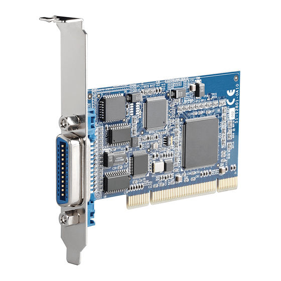
Thank you for choosing a Keithley Instruments product. The KPCI-488LPA has the following features:
Full compatibility with the IEEE488.2 standard
Up to 1.5 MB per second data transfer rates
Supports a 32-bit 3.3 V or 5 V PCI bus
A built-in 1 KB first-in first-out (FIFO) for read/write operations
Half-sized printed circuit board
Supports up to 14 stand-alone instruments
An interactive utility for testing and diagnostics
Command-compatible driver API (application program interfaces) for Keithley Instruments, National
TM
Instruments NI
Contact and support information
This guide is designed to help you to install your KPCI-488LPA. For more detailed information, refer to the
Models KPCI-488LPA and KUSB-488B Reference Manual (part number KI488-901-01), available from the
Keithley Instruments website
From the website, you can also access updated drivers and information about related products.
Your local Field Applications Engineer can help you with product selection, configuration, and usage. Check the
website for contact information.
Inspection for damage
The KPCI-488LPA was carefully inspected electrically and mechanically before shipment. After unpacking all
items from the shipping carton, check for any obvious signs of physical damage that may have occurred during
transit. Report any damage to the shipping agent immediately. Save the original packing carton for possible
future shipment.
KPCI-488LPA-903-01 Rev. B / January 2020
KPCI-488LPA GPIB Controller Interface Card
, and VISA (Virtual Instrument Software Architecture) libraries.
(tek.com/keithley).
*PKPCI-488LPA-903-01B*
Quick Start Guide
1
Advertisement
Table of Contents

Related Manuals for Tektronix Keithley KPCI-488LPA


Summary of Contents for Tektronix Keithley KPCI-488LPA
- Page 1 KPCI-488LPA GPIB Controller Interface Card Keithley Instruments Quick Start Guide 28775 Aurora Road Cleveland, Ohio 44139 1-800-935-5595 tek.com/keithley Welcome Thank you for choosing a Keithley Instruments product. The KPCI-488LPA has the following features: Full compatibility with the IEEE488.2 standard ...
-
Page 2: Software And Hardware Installation
KPCI-488LPA GPIB Controller Interface Card Quick Start Guide Repacking for return shipment Should it become necessary to return the KPCI-488LPA for repair, carefully pack the entire instrument in its original packing carton or the equivalent, and follow these instructions: Call Keithley Instruments’... - Page 3 KPCI-488LPA GPIB Controller Interface Card Quick Start Guide 5. The driver installation dialog window opens, as shown in the following figure. Figure 2: KUSB-488 driver installation screen 6. Install one of the following drivers. The InstallShield Wizard provides guidance on which driver to install. ...
-
Page 4: Hardware Installation
KPCI-488LPA GPIB Controller Interface Card Quick Start Guide Hardware installation The KPCI-488LPA contains sensitive components that can easily be damaged by static electricity. Handle the module on a grounded anti-static mat. The operator should be wearing an anti-static wristband, grounded at the same point as the anti-static mat. You must install the drivers before installing the hardware. - Page 5 KPCI-488LPA GPIB Controller Interface Card Quick Start Guide Cabling For optimal GPIB throughput, adhere to the following cabling guidelines: The longest distance between two devices cannot exceed 4 m. The average GPIB bus distance between all devices should be less than 2 m. ...
- Page 6 KPCI-488LPA GPIB Controller Interface Card Quick Start Guide Figure 4: Star connection configuration GPIB connection configuration The GPIB has 24 lines. These lines consist of 16 signal lines and eight ground-return or shield-drain lines . The 16 signal lines can be divided into a set of eight parallel (8-bit) data transfer bus lines and a set of eight control lines.
-
Page 7: Data Lines
KPCI-488LPA GPIB Controller Interface Card Quick Start Guide GPIB BUS Type Function Number Description DIO1 DIO2 DIO3 DIO4 8 data lines DIO5 DIO6 DIO7 16 signal lines DIO8 5 system management lines 8 control lines 24 lines 3 handshake lines NRFD NDAC 1 shield drain line... -
Page 8: Handshake Lines
KPCI-488LPA GPIB Controller Interface Card Quick Start Guide Handshake lines Three handshake lines control the transfer of data/messages between devices: DAV (Data Valid): Used to indicate the availability and validity of information on the DIO signal lines. NRFD (Not Ready For Data): Used to indicate readiness of devices to accept data. ... - Page 9 KPCI-488LPA GPIB Controller Interface Card Quick Start Guide Using the Keithley GPIB Configuration Utility The Keithley GPIB Configuration Utility allows you to configure the following settings: KPCI-488LPA bus address Bus timing I/O timeout Set the KPCI-488LPA to be a system controller ...
- Page 10 KPCI-488LPA GPIB Controller Interface Card Quick Start Guide 3. Double-click the interface icon to open the GPIB Interface & Bus Setting dialog box. 4. Make any changes to the configuration, then select OK. Figure 8: GPIB interface and bus configuration 5.
- Page 11 KPCI-488LPA GPIB Controller Interface Card Quick Start Guide To use the diagnostic tool: 1. From Windows, select Start > All Programs. 2. From the programs selection, select Keithley Instruments > KI-488 Diagnostic Tool. The KI-488 Diagnostic Tool window will open. Figure 9: KI-488 Diagnostic Tool To initialize your GPIB interface accessory: 1.
- Page 12 KPCI-488LPA GPIB Controller Interface Card Quick Start Guide Figure 10: Specifying the GPIB board address 2. Enter the address to assign to your GPIB interface. The default is 21. 3. Select OK. To communicate with a GPIB-connected instrument: 1. Enter the instrument GPIB address. Figure 11: Specifying the instrument address 2.
-
Page 13: Safety Precautions
Safety precautions The following safety precautions should be observed before using this product and any associated instrumentation. Although some instruments and accessories would normally be used with nonhazardous voltages, there are situations where hazardous conditions may be present. This product is intended for use by personnel who recognize shock hazards and are familiar with the safety precautions required to avoid possible injury. - Page 14 For safety, instruments and accessories must be used in accordance with the operating instructions. If the instruments or accessories are used in a manner not specified in the operating instructions, the protection provided by the equipment may be impaired. Do not exceed the maximum signal levels of the instruments and accessories. Maximum signal levels are defined in the specifications and operating information and shown on the instrument panels, test fixture panels, and switching cards.
Need help?
Do you have a question about the Keithley KPCI-488LPA and is the answer not in the manual?
Questions and answers