Advertisement
Quick Links
Keithley Instruments
28775 Aurora Road
Cleveland, Ohio 44139
1-800-833-9200
tek.com/keithley
Overview
The Keithley Instruments Model 4225-RPM Remote Preamplifier/Switch Module (RPM) is a remote amplifier
and automatic switch. It is a multiplexer switch that automatically switches between precision dc
source-measure units (SMUs), C-V, and the ultra-fast pulsed I-V instruments.
The RPM also extends the low current measurement capability of the 4225-PMU Ultra-Fast Pulsed I-V
Instrument Module. This is especially important for devices like diodes or transistors that have I-V curves that
extend over several decades of current. The autorange feature of the 4225-RPM enables automatic range
selection while a pulsed I-V sweep is in progress. This feature provides optimal current measurement while the
device signal transitions through different current levels. The RPM adds the following current ranges to the
4225-PMU: 100 nA, 1 μA, 10 μA, 100 μA, 1 mA, and 10 mA.
PA-1086 Rev. B March 2023
Remote Pulse Module Instructions
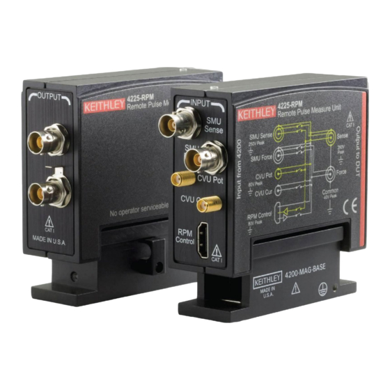
Figure 1: 4225-RPM
*PPA-1086B*
Model 4225-RPM
1
Advertisement

Related Manuals for Tektronix KEITHLEY 4225-RPM


Summary of Contents for Tektronix KEITHLEY 4225-RPM
- Page 1 Model 4225-RPM Keithley Instruments Remote Pulse Module Instructions 28775 Aurora Road Cleveland, Ohio 44139 1-800-833-9200 tek.com/keithley Overview The Keithley Instruments Model 4225-RPM Remote Preamplifier/Switch Module (RPM) is a remote amplifier and automatic switch. It is a multiplexer switch that automatically switches between precision dc source-measure units (SMUs), C-V, and the ultra-fast pulsed I-V instruments.
-
Page 2: Included Accessories
Model 4225-RPM Remote Pulse Module Instructions Included accessories The following cables, adapters, and accessories are included in the remote pulse module kit. Figure 2: 4225-RPM included accessories Item Description Keithley part number Quantity RPM interconnect cable, 2.4 m (8 ft) CA-547-2.4 Triaxial to BNC adapter (guard removed) CS-712... - Page 3 Model 4225-RPM Remote Pulse Module Instructions Indicators When the RPM is operational in a 4200A-SCS system, an LED on top of the RPM illuminates. The color of the LED indicates which instrument is connected to the DUT during a test. Use the color codes in the following figure to determine which instrument is connected.
- Page 4 Model 4225-RPM Remote Pulse Module Instructions With system power off, use the supplied RPM cable to connect a 4225-RPM to the matching RPM channel of the 4225-PMU, as shown in the following figure. Figure 4: 4225-PMU connection to an RPM With an RPM installed, never make connections directly to any of the SMA connectors (CH1 and CH2) on the PMU.
- Page 5 Model 4225-RPM Remote Pulse Module Instructions Connections to a 4-terminal device The following illustrates the connection to a 4-terminal device using the cabling and adapters that are included with either RPM or the 4225-PMU. Figure 5: RPM output connection to 4-terminal device PA-1086 Rev.
- Page 6 Model 4225-RPM Remote Pulse Module Instructions Typical 2-terminal connections The following figure illustrates the connections to 2-terminal devices using the optional MMPC cabling. This figure shows two RPMs and two 4210-MMPC cable kits. Figure 6: Typical diode connections PA-1086 Rev. B March 2023...
- Page 7 Model 4225-RPM Remote Pulse Module Instructions Typical 4-terminal device connections The following figure shows RPM connections to a 4-terminal device using three optional MMPC cable kits. Figure 7: Typical MOSFET connection Load-line effect The load-line effect causes voltage across the DUT to be lower than the programmed source voltage. The output resistance of a pulsing instrument causes this effect.
- Page 8 Model 4225-RPM Remote Pulse Module Instructions The load line is defined by V and the resistance of the pulse instrument. The output resistance of the 4225-PMU entirely determines its slope. The 4225-PMU programmed source voltage determines its horizontal position. Larger voltages shift the line to the right. Smaller voltages shift it to the left. For a given programmed source voltage, the actual DUT voltage cannot go beyond this line.
-
Page 9: Safety Precautions
Safety precautions The following safety precautions should be observed before using this product and any associated instrumentation. Although some instruments and accessories would normally be used with nonhazardous voltages, there are situations where hazardous conditions may be present. This product is intended for use by personnel who recognize shock hazards and are familiar with the safety precautions required to avoid possible injury. - Page 10 For safety, instruments and accessories must be used in accordance with the operating instructions. If the instruments or accessories are used in a manner not specified in the operating instructions, the protection provided by the equipment may be impaired. Do not exceed the maximum signal levels of the instruments and accessories. Maximum signal levels are defined in the specifications and operating information and shown on the instrument panels, test fixture panels, and switching cards.
Need help?
Do you have a question about the KEITHLEY 4225-RPM and is the answer not in the manual?
Questions and answers