
Subscribe to Our Youtube Channel
Related Manuals for Moxa Technologies BXP-A100 Series


Summary of Contents for Moxa Technologies BXP-A100 Series
- Page 1 BXP-A100 Series Hardware User Manual Version 1.0, December 2023 www.moxa.com/products © 2023 Moxa Inc. All rights reserved.
- Page 2 BXP-A100 Series Hardware User Manual The software described in this manual is furnished under a license agreement and may be used only in accordance with the terms of that agreement. Copyright Notice © 2023 Moxa Inc. All rights reserved. Trademarks The MOXA logo is a registered trademark of Moxa Inc.
-
Page 3: Table Of Contents
Table of Contents Introduction ............................5 Package Checklist ..........................5 Product Features ........................... 5 BXP-A100 Hardware Specifications ......................5 Hardware Introduction ......................... 6 Appearance ............................6 Dimensions ............................9 LED Indicators ............................. 11 Reset Button ............................11 Real Time Clock (RTC) .......................... 11 Hardware Connection Description....................... - Page 4 Enroll Customer Key ........................40 Upgrading the BIOS ..........................41 Regulatory Approval Statement ......................46...
-
Page 5: Introduction
Rich interface options of up to 10 serial ports or up to 10 LAN ports. • -30 to 60°C wide operating temperature range • Compact size to fit in various field applications • BXP-A100 Hardware Specifications NOTE The latest specifications for Moxa’s products can be found at https://moxa.com. BXP-A100 Series Hardware User Manual... -
Page 6: Hardware Introduction
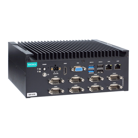
Appearance Front View BXP-A100-E2-T/BXP-A100-E4-T Models BXP-A100-E2-8L-T/BXP-A100-E4-8L-T Models BXP-A100 Series Hardware User Manual... - Page 7 BXP-A100-E2-8C-T/BXP-A100-E4-8C-T Models BXP-A100-E2-2L3C-T/BXP-A100-E4-2L3C-T Models Rear View BXP-A100-E2-T/BXP-A100-E4-T Models BXP-A100 Series Hardware User Manual...
- Page 8 BXP-A100-E2-8L-T/BXP-A100-E4-8L-T Models BXP-A100-E2-8C-T/BXP-A100-E4-8C-T Models BXP-A100-E2-2L3C-T/BXP-A100-E4-2L3C-T Models BXP-A100 Series Hardware User Manual...
-
Page 9: Dimensions
Dimensions BXP-A100-E2-T/BXP-A100-E4-T Models BXP-A100-E2-8L-T/BXP-A100-E4-8L-T Models BXP-A100 Series Hardware User Manual... - Page 10 BXP-A100-E2-8C-T/BXP-A100-E4-8C-T Models BXP-A100-E2-2L3C-T/BXP-A100-E4-2L3C-T Models BXP-A100 Series Hardware User Manual...
-
Page 11: Led Indicators
Contact a qualified Moxa support engineer if you have any questions about the RTC battery. ATTENTION There is a risk of explosion if the battery is replaced by a battery of the incorrect type. BXP-A100 Series Hardware User Manual... -
Page 12: Hardware Connection Description
To mount the BXP-A100 computer to a wall or cabinet, use two screws on each side for the mounting brackets as shown in the illustration. NOTE The four screws for attaching the wall-mounting brackets to the wall or cabinet are NOT included in the product package; they need to be purchased separately. BXP-A100 Series Hardware User Manual... - Page 13 NOTE This computer is intended to be installed only in an area with restricted access. In addition, for safety reasons, the computer should be installed and handled only by qualified and experienced professionals. BXP-A100 Series Hardware User Manual...
-
Page 14: Connecting The Power
Moxa technical support team. NOTE If using Class I adapter, the power cord adapter should be connected to a socket outlet with an earthing connection or the power cord and adapter must comply with Class II construction. BXP-A100 Series Hardware User Manual... -
Page 15: Communication Connections
ETx- TRD(0)- ERx+ TRD(1)+ – TRD(2)+ – TRD(2)- ERx- TRD(1)- – TRD(3)+ – TRD(3)- NOTE For reliable Ethernet connections, we recommend enabling the ports in standard temperatures and keeping them enabled in high/low temperature environments. BXP-A100 Series Hardware User Manual... -
Page 16: Connecting To A Serial Device
Logic 1: Open DI Dry Contact DO Contact Connecting Displays The BXP-A100 Series computer comes with a VGA and an HDMI display output located on the front panel. NOTE For reliable video streaming, use premium HDMI-certified cables. BXP-A100 Series Hardware User Manual... -
Page 17: Connecting To A Usb Device
To remove the cards, simply push them in to release them and take them out. Replacing the RTC Battery The BXP-A100 Series computer comes with one slot for a battery on the rear panel of the computer. A lithium battery (3 V / 200 mAh) is preinstalled in the slot. - Page 18 Plug in the connector of the battery-cover assembly to the internal wire of the slot. Place the battery holder back in the slot and secure it by fastening the two screws on the cover. BXP-A100 Series Hardware User Manual...
- Page 19 Moxa’s technical support staff for assistance, if necessary. To reduce the risk of fire or burns, do not disassemble, crush, or puncture the battery; do not dispose • of in fire or water and do not short external contacts. BXP-A100 Series Hardware User Manual...
-
Page 20: Bios Setup
• Boot From File: Select the UEFI boot up file • Administer Secure Boot: Enter the Secure Boot menu • Setup Utility: Enter the BIOS configuration menu • Select F2 to enter the BIOS configuration. BXP-A100 Series Hardware User Manual... - Page 21 Select or go to Submenu. EN TER The BIOS configuration screen will be shown when you enter the Setup Utility option. NOTE The Processor Type information may vary depending on the model that you have purchased. BXP-A100 Series Hardware User Manual...
-
Page 22: Main Page
Main Page The Main page displays basic hardware information, such as model name, BIOS version, and CPU type. Advanced Settings Select the Advanced tab in the main menu to open the advanced features screen. BXP-A100 Series Hardware User Manual... -
Page 23: Boot Configuration
Boot Configuration The Numlock option allows configuration of the Numlock value Options: On (default), Off. BXP-A100 Series Hardware User Manual... -
Page 24: Sata Configuration
SATA Port Hot Plug This setting allows you to enable/disable hot-plugging capabilities (the ability to remove the drive while the computer is running) that are configured by software for installed storage drives. Options: Disabled (default), Enabled BXP-A100 Series Hardware User Manual... -
Page 25: Cpu Configuration
This item indicates the number of cores to enable in each processor package (Cores number depended on the processor). Options: All (default), 1, 2, 3 Turbo Mode Enable/Disable processor Turbo Mode (not supported in models with Intel® Celeron® ). Options: Disabled, Enabled (default) BXP-A100 Series Hardware User Manual... -
Page 26: Video Configuration
2D/3D graphics performance. DVMT Total Gfx Mem. This item allows you to configure the maximum amount of memory DVMT will use when allocating additional memory for the internal graphics device. Options: 256 MB (default), 128 MB, Max. BXP-A100 Series Hardware User Manual... -
Page 27: Chipset Configuration
Load Default After Cleaning RTC Battery System will load default when detecting RTC battery loss. Options: Disabled, Enabled (default) DO-X Level This item allows users to set the DO to high or low. Options: High (default), Low BXP-A100 Series Hardware User Manual... -
Page 28: Console Redirection
This section allows you to configure the console redirection settings. Console Serial Redirect When the Console Redirection Function is enabled, the console information will be sent both to the display monitor and the serial port (COM1). Options: Disabled (default), Enabled BXP-A100 Series Hardware User Manual... -
Page 29: Sio Ite8786E
SIO ITE8786E This section allows users to configure SIO settings. BXP-A100 Series Hardware User Manual... -
Page 30: Hardware Monitor
Enable: Enable the UART port 2 connection (default) NOTE All other UART ports can only be configured by an OS utility. Hardware Monitor This section allows you to view stats such as CPU and system temperature, voltage levels, and other chipset information. BXP-A100 Series Hardware User Manual... -
Page 31: Security Settings
This item shows if the system has TMP device and its type. TPM State This item allows you view the status of current TPM settings. Clear TPM This item allows users to remove all TPM context associated with a specific owner. BXP-A100 Series Hardware User Manual... -
Page 32: Set Supervisor Password
This item allows you to set the supervisor password. Select the Set Supervisor Password option and enter the password and confirm the password again. To delete the password, select the Set Supervisor Password option and enter the old password; leave the new password fields blank, and then press enter. BXP-A100 Series Hardware User Manual... - Page 33 Enable: System will ask for the password on post time Disable: System will ask for the password to go to the setup utility Config-Only: System will only ask for the password when you select the config (F2) option BXP-A100 Series Hardware User Manual...
-
Page 34: Power Settings
Options: Disabled (default); By Every Day (user specifies a regular daily time when the computer will power up); By Day of Month (user specifies a regular day each month when the computer will power up) BXP-A100 Series Hardware User Manual... -
Page 35: Boot Settings
PXE Booting is booting a system over a network. This item allows users to start PXE over IPv4 or IPv6 Options: Disabled (default), UEFI: IPv4, UEFI: IPv6, UEFI: IPv4/IPv6 USB Boot Set booting to USB boot devices capability. Options: Enabled (Default), Disabled BXP-A100 Series Hardware User Manual... -
Page 36: Timeout
This item allows users to set the number of seconds that the firmware will wait before booting from the default boot selection. This item allows users to select the boot order. Use F5 (move down) or F6 (move up) to change the boot order. BXP-A100 Series Hardware User Manual... -
Page 37: Exit Settings
This item allows you to exit without saving any changes that might have been made to the BIOS. Options: Yes (default), No Load Optimal Defaults This item allows you to revert to the factory default BIOS values. Options: Yes (default), No BXP-A100 Series Hardware User Manual... -
Page 38: Load Custom Defaults
Secure Boot helps computers resist attacks and infection from malware. The feature defines an interface between the operating system and BIOS. It detects tampering with boot loaders, key operation system files, and unauthorized option ROMs by validating their digital signatures. BXP-A100 Series Hardware User Manual... -
Page 39: Enabling Uefi Secure Boot
Set as “enabled” in “Restore Secure Boot to Factory Settings” under Administer Secure Boot menu. Press F10 as save and exist. Moxa has included the Microsoft key in the BIOS by default. If you cannot boot up the computer using a non-Windows OS, use the following examples. Enroll EFI Image BXP-A100 Series Hardware User Manual... - Page 40 Enter Administer Secure Boot and select the option Select a UEFI file as trusted for execution. Enter the loader name followed by the UEFI standard \EFI\BOOT\BOOT{machine type short-name}. E.g., efi\boot\BootX64.efi, Debian (EFI\debian\grubx64.efi), Suse (EFI\opensuse\grubx64.efi) Enroll Customer Key BXP-A100 Series Hardware User Manual...
- Page 41 It is possible to permanently damage the computer when upgrading the BIOS. We strongly recommend that you contact Moxa’s technical support staff for assistance to obtain all the necessary tools and the most current advice before attempting to upgrade the BIOS on any Moxa device. BXP-A100 Series Hardware User Manual...
- Page 42 Before upgrading the BIOS, you must create a bootable USB drive as a system boot device for use in the future. Insert a USB disk in the computer’s USB drive. Search for “format” and select Create and format hard disk partitions. Right-click on the USB disk item and select Format. BXP-A100 Series Hardware User Manual...
- Page 43 Select the USB Disk. The screen will switch to the SHELL environment. Type fs0:, go to the directory where the upgrade file is located, and type xxxxxx.efi (the file name is based on the upgrade file from Moxa). BXP-A100 Series Hardware User Manual...
- Page 44 When the upgrade is finished, the computer will automatically reboot. You can check the BIOS version on the Main page to confirm the upgrade. If the system has more than one boot device, you will see more than one fsx (x represents the number). BXP-A100 Series Hardware User Manual...
- Page 45 Go to each fsx (x stands for the number) and type ls to view the content of the boot device. If you find an upgrade file, run it. BXP-A100 Series Hardware User Manual...
- Page 46 This is a class A product. If used in a domestic environment, this product may cause undesirable radio interference, in which case the user may be required to take adequate measures to prevent the interference from affecting nearby devices. BXP-A100 Series Hardware User Manual...
Need help?
Do you have a question about the BXP-A100 Series and is the answer not in the manual?
Questions and answers