
Related Manuals for Moxa Technologies BXP Series


Summary of Contents for Moxa Technologies BXP Series
- Page 1 BXP Series Quick Installation Guide Embedded Computers Version 1.0, September 2023 Technical Support Contact Information www.moxa.com/support 2023 Moxa Inc. All rights reserved. P/N: 1802001001010 *1802001001010*...
-
Page 2: Package Checklist
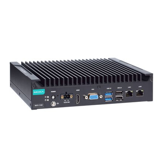
Overview The BXP Series wall-mount computers are powered by an Intel Atom®, Intel® Celeron®, or Intel® Core™ i5/i7 processor. The computers come with a rich set of interface options including up to 10 software- selectable RS-232/422/485 serial ports, up to 10 gigabit Ethernet ports, 4 digital inputs, and 4 digital outputs. - Page 3 BXP-C100-C1-8C-T/BXP-C100-C5-8C-T/BXP-C100-C7-8C-T Models BXP-C100-C1-2L3C-T/BXP-C100-C5-2L3C-T/BXP-C100-C7-2L3C-T Models BXP-A100-E2-T/BXP-A100-E4-T Models BXP-A100-E2-8L-T/BXP-A100-E4-8L-T Models - 3 -...
- Page 4 BXP-A100-E2-8C-T/BXP-A100-E4-8C-T Models BXP-A100-E2-2L3C-T/BXP-A100-E4-2L3C-T Models Rear View BXP-C100-C1-T/BXP-C100-C5-T/BXP-C100-C7-T/BXP-A100-E2-T/BXP- A100-E4-T Models BXP-C100-C1-8L-T/BXP-C100-C5-8L-T/BXP-C100-C7-8L-T/BXP-A100-E2- 8L-T/BXP-A100-E4-8L-T Models - 4 -...
- Page 5 BXP-C100-C1-8C-T/BXP-C100-C5-8C-T/BXP-C100-C7-8C-T/BXP-A100-E2- 8C-T/BXP-A100-E4-8C-T Models BXP-C100-C1-2L3C-T/BXP-C100-C5-2L3C-T/BXP-C100-C7-2L3C-T/BXP- A100-E2-2L3C-T/BXP-A100-E4-2L3C-T Models Dimensions BXP-C100-C1-T/BXP-C100-C5-T/BXP-C100-C7-T/BXP-A100-E2-T/BXP- A100-E4-T Models - 5 -...
- Page 6 BXP-C100-C1-8L-T/BXP-C100-C5-8L-T/BXP-C100-C7-8L-T/BXP-A100-E2- 8L-T/BXP-A100-E4-8L-T Models BXP-C100-C1-8C-T/BXP-C100-C5-8C-T/BXP-C100-C7-8C-T/BXP-A100-E2- 8C-T/BXP-A100-E4-8C-T Models BXP-C100-C1-2L3C-T/BXP-C100-C5-2L3C-T/BXP-C100-C7-2L3C-T/BXP- A100-E2-2L3C-T/BXP-A100-E4-2L3C-T Models - 6 -...
- Page 7 LED Indicators The following table describes the LED indicators located on the front panel of BXP computers. LED Name Status Function Power Green Power is ON No power input or any other power error Ethernet Green Steady ON: 10/100 Mbps Ethernet link (10/100 Blinking: Data is being transmitted or Mbps)
- Page 8 To mount a BXP computer to a wall or cabinet, use two screws on each side for the mounting brackets as shown in the illustration. NOTE The four screws for attaching the wall-mounting brackets to the wall or cabinet are NOT included in the product package; they need to be purchased separately.
-
Page 9: Connecting The Power
Connecting the Power The BXP computer is provided with 2-pin power input connectors in a terminal block on the front panel. Insert the power-cord wires into the connectors and tighten them to secure the wires in place. Push the power button. The power LED will light up to indicate that power is being supplied to the computer. -
Page 10: Connecting Displays
Communications Connections USB Ports The BXP Series computer comes with 2 USB 3.0 ports and 2 USB 2.0 ports on the front panel. An additional 2 USB 2.0 ports are located on the rear panel. The USB ports can be used to connect to peripherals, such as keyboard, mouse, or flash drives for expanding the system’s... -
Page 11: Digital Inputs/Digital Outputs
Voltage: Voltage: 0 to 24 VDC 0 to 24 VDD For detailed wiring methods, refer to the BXP Series Hardware User Manual. SD / CFast Card The BXP computer comes with two slots for plugging in an SD card and a CFast card. - Page 12 To replace the battery, do the following: 1. Unfasten the two screws on the battery cover. 2. Take off the cover. The battery is attached to the slot cover as indicated in the image. 3. Unplug the connector of the battery-cover assembly from the internal wire of the slot.
- Page 13 Warning Be sure to use the correct type of battery. Incorrect • battery may cause system damage. Contact Moxa’s technical support staff for assistance, if necessary. To reduce the risk of fire or burns, do not disassemble, • crush, or puncture the battery; do not dispose of in fire or water and do not short external contacts.
Need help?
Do you have a question about the BXP Series and is the answer not in the manual?
Questions and answers