Subscribe to Our Youtube Channel
Summary of Contents for Clarke STRONG-ARM CHDDWD
- Page 1 WHEEL DOLLY MODEL NO: CHDDWD PART NO: 7620100 OPERATION AND MAINTENANCE INSTRUCTIONS ORIGINAL INSTRUCTIONS GC-02/23...
-
Page 2: Product Features
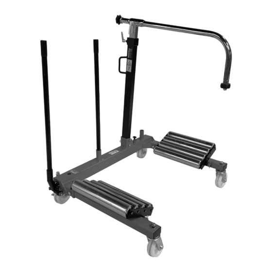
INTRODUCTION Thank you for purchasing this CLARKE product. The CHDDWD Wheel Dolly is designed for effortless, fast and safe removal, handling and fitting of agricultural, industrial and commercial wheels. The lifting action is achieved using a two stage hydraulic pump mounted inside the frame. -
Page 3: Specifications
OVERVIEW SPECIFICATIONS Dimensions (L x W x H) Minimum Extension 1340 x 1160 x 940 mm Dimensions (L x W x H) Maximum Extension 2080 x 1650 x 940 mm Weight 118 kg Maximum load capacity 1200 kg Maximum tyre width 810 mm Maximum wheel diameter 2000... -
Page 4: Safety Precautions
SAFETY PRECAUTIONS GENERAL 1. ALWAYS read and ensure you fully understand the following precautions and the hazards associated with this product. DO NOT allow anyone who has not read these instructions to use this product. 2. Only use this product for its intended purpose. 3. -
Page 5: Servicing & Repairs
Any damage should be properly repaired or the defective part replaced. If in doubt, DO NOT use. 2. ALWAYS use spare parts supplied by Clarke International. Using non- standard parts could be extremely dangerous. 3. Ensure that this product is properly maintained at all times and that no corrosion or other damage is allowed to weaken any part of it. - Page 6 ASSEMBLY Unpack the components and remove packing materials. Before proceeding, please check contents against the overview and parts list & diagram on pages 12/13 and advise your dealer immediately if any parts are missing. NOTE: Refer to the components diagram on pages 12/13 for parts identity.
- Page 7 7. Use the pin (30), R-clip (31) to fix the lower column (19) to the outer frame (10). • 2 x pins & R-clips are used as shown. 8. Fit the sliding column (22) into the lower column (19) and then secure in your chosen position with the height adjustment clamp (18).
-
Page 8: Operation
OPERATION WARNING: MAKE SURE THAT THE SAFETY PRECAUTIONS ARE STRICTLY FOLLOWED. NO RESPONSIBILITY CAN BE ACCEPTED FOR INCORRECT USE OF THE DOLLY. Before use, visually inspect the dolly for distortion of parts, cracked welds, damaged castors, oil leaks, or any other sign of damage. Should any of these be apparent, have the dolly inspected and repaired by a qualified technician before putting back into use. -
Page 9: Unloading The Dolly
NOTE: The angle of the wheel supports can be adjusted by the removal of locking pin to accommodate different wheel configurations. WARNING! WHEEL SUPPORT COLUMN AND RETAINING ARM ARE ONLY USED TO BALANCE THE WHEEL, NOT TO CARRY A LOAD! 9. -
Page 10: Care And Maintenance
If the dolly has been stored for long periods, check for oil leaks before use and top up via the oil refill plug on the oil reservoir if necessary. • Oil can be topped up using Clarke Hydraulic Oil, part no: 3050830 for 1 litre, part no. 3050835 for 5 litres). -
Page 11: Troubleshooting
Pump pedal to purge air from ram. O-ring worn. Return to your dealer for overhaul. Dolly will not hold load Release valve not tightly Speak to the Clarke and beams move closed. Service Department slowly apart. Release valve not seating. Return to your Clarke dealer for overhaul. -
Page 12: Component Parts
COMPONENT PARTS Parts & Service: 020 8988 7400 / E-mail: Parts@clarkeinternational.com or Service@clarkeinternational.com... - Page 13 COMPONENT PARTS ESCRIPTION ESCRIPTION Sliding column Right support beam Roller table assembly Rectangular end plug Retaining arm Support arm roller Roller table mounting rod Nut M16 Hand grip Flat washer 16 Castor wheel assy without brake Frame corner section Hex socket screw Hydraulic ram assembly 29 Hand tensioning knob Inner frame...
- Page 14 DECLARATION OF CONFORMITY-UK Parts & Service: 020 8988 7400 / E-mail: Parts@clarkeinternational.com or Service@clarkeinternational.com...
-
Page 15: Declaration Of Conformity (Ce)
DECLARATION OF CONFORMITY - CE Parts & Service: 020 8988 7400 / E-mail: Parts@clarkeinternational.com or Service@clarkeinternational.com...


Need help?
Do you have a question about the STRONG-ARM CHDDWD and is the answer not in the manual?
Questions and answers