Table of Contents
Advertisement
Quick Links
Application Note – AS5000 Programmer
1 General Overview
This operational manual describes the function of the AS5000 Programmer in combination with the programming
boards. This tool can program the ams AS5000 series magnetic rotary encoders. The graphical user interface (GUI)
runs on PC running Windows XP or later and controls the programmer via the USB interface.
All major access modes to the OTP memories can be established. Be aware that ams provides the AS5000
Programmer as a reference for programming and reading of mentioned devices (refer to
Appendix A) under laboratory conditions (no warranty for mass production).
Note: Since firmware version v2.10 the AS5000-Programmer contains a boot loader, which provides an update function
for new software release. Please refer to the corresponding application note AN5000-60 (available on our
webpage).
2 Hardware Components
2.1
Description of the Hardware Components
LCD display
USB cable
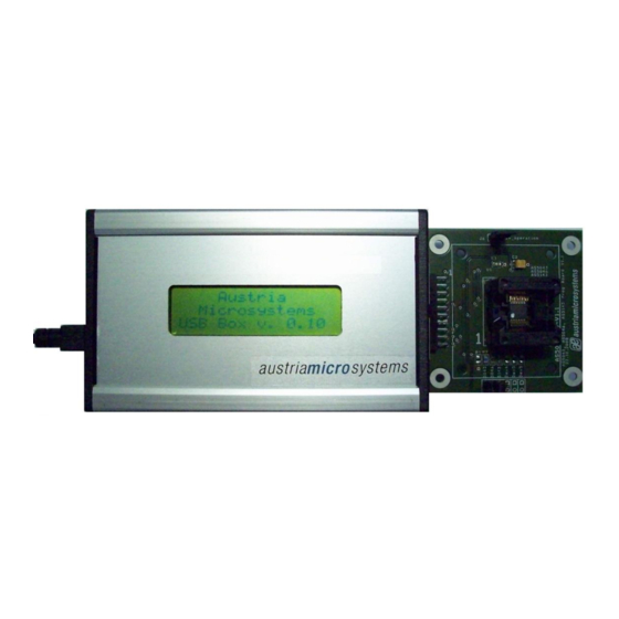
Figure 1 shows the three components which are needed to program the ams magnetic position sensor. Take care that
the connector between programmer and programming board is plugged in the right way.
In case of wrong connection, the components in the AS5000 programmer or the encoder can be destroyed!
www.ams.com
(programmer v1.3 or older only)
AS5000 programmer
Figure 1: Three components of the Programmer solutio n
Warning:
Programming board
(AS5xxx-PB)
Revision 1.11/ 02/18/2014
Advertisement
Table of Contents

Related Manuals for AMS AN5000 Series


Summary of Contents for AMS AN5000 Series
-
Page 1: General Overview
Figure 1: Three components of the Programmer solutio n Figure 1 shows the three components which are needed to program the ams magnetic position sensor. Take care that the connector between programmer and programming board is plugged in the right way. - Page 2 Encoder signal Encoder signal Encoder power supply Encoder power supply Ground Ground Encoder signal Encoder & LCD display signal Encoder signal LCD signal – Do not use Encoder & LCD display signal Encoder & LCD display signal www.ams.com Revision 1.11/ 02/18/2014...
-
Page 3: Description Of The Programming Board
With this jumper the gain can set to 1. The jumper J6 is by default closed because the AS5000 Programmer provides 3.3V operation. In case of 5 V operation the jumper must be removed and the configuration can be changed over the GUI. www.ams.com Revision 1.11/ 02/18/2014... -
Page 4: Installation
Following Procedure is recommended before starting the GUI: check on your PC if Service Pack 2 is installed install the mentioned .net package to your computer execute AS5000GUI_setup.exe Finally start the GUI using the shortcut in the start menu or desktop. www.ams.com Revision 1.11/ 02/18/2014... -
Page 5: Graphical User Interface (Gui)
(FW) type of the connected hardware: ubox (AS5000 Programmer) or dbrd (Demoboard) firmware (FW) version By default the GUI is in the auto detection mode. Any ams device connected on the USB port (one device at the same time) will be automatically detected and displayed in the right top corner. -
Page 6: Programming The As5040/As5045/As5140/As5145/As5045B
Status field displays the status bits extracted from the SSI stream. Green light means that the airgap between the magnet and encoder is correct. Orange light means the magnet is too close of too far. CCW checkbox is the angle direction. To invert the rotating direction, check CCW. www.ams.com Revision 1.11/ 02/18/2014... - Page 7 Selecting Zero Position Reset will write the value 0 to the OTP Zero Position register. Note: The Zero Position function is the same for all the AS50xx, AS51xx, AS52xx rotary encoders offering this feature. Selecting the OTP tab will read the OTP configuration from the IC. www.ams.com Revision 1.11/ 02/18/2014...
- Page 8 Write writes the bits checked by the user into the volatile OTP register. Selecting the SSI after the configuration is possible to check the effect. Zap! writes permanently the checked OTP bits to the encoder’s fuses. www.ams.com Revision 1.11/ 02/18/2014...
-
Page 9: Programming The As5043
The actual value will be 0 after zero position programming. To reset the zero position register, or to set a new zero position, click on Reset first. Read interval is the SSI stream readout and refresh rate the GUI. www.ams.com Revision 1.11/ 02/18/2014... - Page 10 Write writes the bits checked by the user into the volatile OTP register. Selecting the SSI after the configuration is possible to check the effect of the new configuration. Zap! Writes permanently the checked OTP bits to the encoder’s fuses. www.ams.com Revision 1.11/ 02/18/2014...
-
Page 11: Programming The As5245
Status field displays the status bits extracted from the SSI stream. Green light means that the airgap between the magnet and encoder is correct. Orange light means the magnet is too close of too far. CCW checkbox is the angle direction. To invert the rotating direction, check CCW. www.ams.com Revision 1.11/ 02/18/2014... - Page 12 Write writes the bits checked by the user into the volatile OTP register. Selecting the SSI after the configuration is possible to check the effect. Zap! writes permanently the checked OTP bits to the encoder’s fuses. www.ams.com Revision 1.11/ 02/18/2014...
-
Page 13: Programming The As5134
The actual value will be 0 after zero position programming. To reset the zero position register, or to set a new zero position, click on Reset first. Read interval is the readout and refresh rate the GUI. www.ams.com Revision 1.11/ 02/18/2014... - Page 14 Write writes the bits checked by the user into the volatile OTP register. Selecting the SSI after the configuration is possible to check the effect of the new configuration. Zap! writes permanently the checked OTP bits to the encoder’s fuses. www.ams.com Revision 1.11/ 02/18/2014...
- Page 15 Application Note – AS5000 Programmer Analog Readback is not implemented yet. It will be available soon. www.ams.com Revision 1.11/ 02/18/2014...
-
Page 16: Programming The As5163/As5263
The connection board provides the load, needed for programming and operating the AS5163/AS5263. Further details concerning all programming options are provided in application note AN5163-10 (available on our webpage). Programming the AS5115/AS5215 Figure 20: AS115-PB Programming Board (left) and AS5215 -PB Programming Board (right) www.ams.com Revision 1.11/ 02/18/2014... - Page 17 Write writes the bits checked by the user into the volatile OTP register. Selecting the SSI after the configuration is possible to check the effect of the new configuration. Zap! writes permanently the checked OTP bits to the encoder’s fuses. www.ams.com Revision 1.11/ 02/18/2014...
-
Page 18: Programming Boards (Pb) Schematics
Application Note – AS5000 Programmer 5 Programming boards (PB) Schematics AS5040-PB-1.1 www.ams.com Revision 1.11/ 02/18/2014... -
Page 19: As5043-Pb-1.1
Application Note – AS5000 Programmer AS5043-PB-1.1 www.ams.com Revision 1.11/ 02/18/2014... -
Page 20: As5115-Pb1.1
Application Note – AS5000 Programmer AS5115-PB1.1 AS5134-PB-1.1 www.ams.com Revision 1.11/ 02/18/2014... -
Page 21: As5163-Pb-1.0
Application Note – AS5000 Programmer AS5163-PB-1.0 AS5215-PB-1.1 AS5245-PB-1.1 www.ams.com Revision 1.11/ 02/18/2014... - Page 22 Application Note – AS5000 Programmer AS5263-PB-1.0 www.ams.com Revision 1.11/ 02/18/2014...
-
Page 23: As5263-Pb-1.0
0.12 ● AS5045 0.12 AS5046 ● Future Release AS5115 ● 2.24 AS5130 ● Future Release AS5134 ● 0.10 AS5140 ● 0.10 AS5145 ● 0.10 AS5163 ● 0.13 AS5215 ● 2.24 AS5245 ● 0.10 AS5263 ● 0.13 www.ams.com Revision 1.11/ 02/18/2014... -
Page 24: Table Of Contents
AS5040-PB-1.1 ............................... 18 AS5043-PB-1.1 ............................... 19 AS5115-PB1.1 ..............................20 AS5134-PB-1.1 ............................... 20 AS5163-PB-1.0 ............................... 21 AS5215-PB-1.1 ............................... 21 AS5245-PB-1.1 ............................... 21 AS5263-PB-1.0 ............................... 22 Appendix A ..................................23 Revision History ................................25 Copyright ..................................26 Disclaimer ..................................26 www.ams.com Revision 1.11/ 02/18/2014... -
Page 25: Revision History
March 3, 2009 AS5x40, AS5x45 chapter added, screenshot updated. R1.8 August 10, 2009 AS5134 updated, AS5143 removed, AS5245 added R1.9 February 04, 2010 AS5115, AS5215, AS5163 and AS5263 added R1.10 March 04, 2010 AS5045B added R1.11 Feb, 2014 www.ams.com Revision 1.11/ 02/18/2014... -
Page 26: Copyright
No obligation or liability to recipient or any third party shall arise or flow out of ams AG rendering of technical or other services.
Need help?
Do you have a question about the AN5000 Series and is the answer not in the manual?
Questions and answers