Sign In
Upload
Manuals
Brands
Inovance Manuals
Servo Drives
IS810N-INT Series
Inovance IS810N-INT Series Manuals
Manuals and User Guides for Inovance IS810N-INT Series. We have
1
Inovance IS810N-INT Series manual available for free PDF download: User Manual
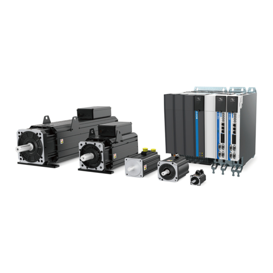
Inovance IS810N-INT Series User Manual (290 pages)
Servo System
Brand:
Inovance
| Category:
Servo Drives
| Size: 30.64 MB
Table of Contents
Preface
2
Table of Contents
5
Chapter 1 Safety Information and Precautions
9
General Safety
9
Acceptance Precautions
10
Storage and Transportation Precautions
10
Installation Precautions
10
Wiring Precautions
11
Maintenance Precautions
12
Check Item and Period
13
Normal Use Conditions
13
Prohibition
13
Disposal Precautions
14
Usage Precautions
14
Chapter 2 Product Information
15
Drive Unit
15
Designation Rules and Nameplate
15
Components of Drive Unit
16
Specifications
17
Servo Motor
20
Specifications of Onecable Motor
20
Specifications of the ISMH Servo Motor Series
24
Specifications of ISMG the Servo Motor Series
33
Specifications of the MS1 Servo Motor Series
40
Servo System Configuration
46
Applicable Cables
48
Cables Applicable for Onecable Servo Motors (Communication Cables Included)
48
Cables Applicable for ISMH Series Servo Motors (Communication Cables Included)
48
Cables Applicable for ISMG Series Servo Motors (Communication Cables Included)
51
Cables Applicable for MS1H Series Servo Motors (Communication Cables Included)
52
Servo System Wiring
53
Chapter 3 Installation
54
Power Supply/Drive Unit Installation
54
Installation Environment
54
Product Dimensions and Installation Space Requirements
56
Servo Drive Installation
61
Cabinet-Mounted Installation
61
Removal and Installation of a Power Supply Unit Cover
63
Wall-Mounted Installation
65
Servo Motor Installation
67
Installation Precautions
67
Installation Environment
70
Overall Dimensions of the ISMH Servo Motor Series
71
Overall Dimensions of the ISMG Servo Motor Series
77
Overall Dimensions of the MS1H Servo Motor Series
79
Chapter 4 Wiring
81
Terminals in a Power Supply Unit
82
Terminals in a Drive Unit
82
Terminal Arrangement in a Drive Unit
82
Function Description of Terminals in Drive Unit
83
Connection of the Power Supply Unit to the Drive Unit
84
Power Connection through the DC Bus
84
PE Connection
85
Control Power Supply
86
Shield Grounding and Hose Clamp
87
Connection of the Drive Unit to the Motor
88
Grounding Requirements
88
Connection to a Onecable Series Servo Motor
88
Connection to an ISMH Series Servo Motor
90
Connection to an ISMG Series Servo Motor
101
Connection to an MS1H Series Servo Motor
105
Brake Wiring
106
STO Connection
108
Application Example of the STO Function
109
Disabling the STO Function
110
RJ45 Communication Connection
111
Control Signal Connection (CN1)
112
Encoder Signal Frequency Division Output and Full Closed-Loop Signal Input Connection (CN5/CN7)
121
Communication Signal Connection (CN3/CN4)
123
Anti-Interference Measures for Electrical Wiring
128
Anti-Interference Wiring Example and Grounding
128
Using Noise Filter
129
Cablen Use Precautions
130
General Wiring Diagram
131
Chapter 5 Keypad
132
Introduction to LED Keypad
132
Keypad Display
135
Monitoring Parameters
140
Parameter Setting
149
User Password
150
Jog Running
151
DI/DO Function
152
Chapter 6 Commissioning Software
155
Basic Setting
155
Check before Run
156
Power Supply Connection
156
Jogging
156
Selection of Output Pulse Phase
158
Drive Stop
159
Conversion Factor Setting
164
Background Commissioning Software
166
Commissioning Cases
174
Basic Settings of the AM600 Controller for OMET
174
Basic Settings of the Beckhoff Controller for OMET
184
Basic Settings of the Omron NJ Controller for OMET
204
Basic Settings of the Trio Controller for OMET
214
Chapter 7 Troubleshooting
230
Power Supply Unit
230
Drive Unit
230
Fault and Warning Grading
230
Communication Fault and Warning Code List
231
Troubleshooting
233
Troubleshooting of Warnings
249
Troubleshooting Communication Faults
253
Appendix 1 List of Object Groups
255
Parameter Address Structure
255
Object Group 1000H
255
Object Group 6000H
259
SDO Abort Transfer Code
289
Appendix 2 General Wiring Diagram
290
Advertisement
Advertisement
Related Products
Inovance IS300S003-C
Inovance IS300T002-C
Inovance IS300T140-C
Inovance IS300T250-C
Inovance IS300-5T020-C
Inovance IS300-5T070-C
Inovance IS300-5T140-C
Inovance IS300-5T460-C
Inovance IS300-5T210-C-L
Inovance IS300-5T300-C-L
Inovance Categories
DC Drives
Controller
Servo Drives
Control Unit
Inverter
More Inovance Manuals
Login
Sign In
OR
Sign in with Facebook
Sign in with Google
Upload manual
Upload from disk
Upload from URL