Pilz PSEN cs2.1p Operating Manual
Hide thumbs
Also See for PSEN cs2.1p:
- Operating instructions manual (9 pages) ,
- Operating instructions manual (10 pages)
Table of Contents
Advertisement
Quick Links
Advertisement
Table of Contents

Subscribe to Our Youtube Channel
Related Manuals for Pilz PSEN cs2.1p


Summary of Contents for Pilz PSEN cs2.1p
- Page 1 PSEN cs2.1p PSEN sensor technology Operating Manual-1003268-EN-10...
- Page 2 We do assure you that all persons are regarded without discrim- ination and on an equal basis. All rights to this documentation are reserved by Pilz GmbH & Co. KG. Copies may be made for the user's internal purposes. Suggestions and comments for improving this documenta- tion will be gratefully received.
-
Page 3: Table Of Contents
Lateral and vertical offset......................Wiring ............................Terminal assignment connectors....................Connection to evaluation devices ..................Single connection ........................Series connection ........................Connection to Pilz evaluation devices ..................Teaching in the actuator ....................... Installation ..........................Adjustment ..........................Operation ..........................Dimensions in mm ......................... - Page 4 Contents Accessories ..........................EC declaration of conformity ....................UKCA-Declaration of Conformity ..................Operating Manual PSEN cs2.1p 1003268-EN-10...
-
Page 5: Introduction
PSEN cs2.1p Introduction Validity of documentation This documentation is valid for the product PSEN cs2.1p from Version 2.0. This operating manual explains the function and operation, describes the installation and provides guidelines on how to connect the product. Using the documentation This document is intended for instruction. -
Page 6: Safety
If installed in other environments, measures should be taken to comply with the applicable standards and directives for the respective installation site with regard to in- terference. Operating Manual PSEN cs2.1p 1003268-EN-10... -
Page 7: Safety Regulations
Are familiar with the basic regulations concerning health and safety / accident prevention, Have read and understood the information provided in the section entitled Safety Have a good knowledge of the generic and specialist standards applicable to the specific application. Operating Manual PSEN cs2.1p 1003268-EN-10... -
Page 8: Warranty And Liability
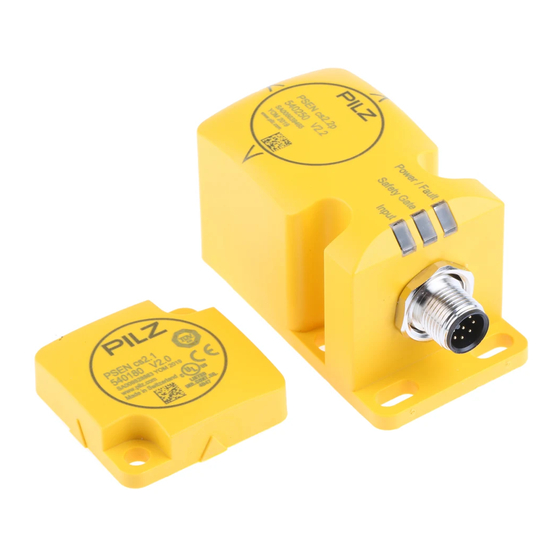
Do not remove the connector's protective cap until you are just about to connect the unit. This will prevent potential contamination. Unit features Transponder technology for presence detection Pilz coding type: fully coded Dual-channel operation 2 safety inputs for series connection of multiple safety switches 2 safety outputs Safety Device Diagnostics (SDD) –... -
Page 9: Function Description
If no fieldbus module of the SDD is used, the diagnostic input Y1 is not used. Signal output/diagnostic output Y32 in SDD mode If a fieldbus module of the SDD is used, the signal output/diagnostic output Y32 is activ- ated for writing data. Operating Manual PSEN cs2.1p 1003268-EN-10... -
Page 10: Safety Device Diagnostics
With Safety Device Diagnostics there are the following diagnostic options for the fieldbus module for simple wiring: – Information is passed on via the fieldbus module directly to the network – Mappings of the signal outputs to the sensor are automated by the SDD. Operating Manual PSEN cs2.1p | 10 1003268-EN-10... -
Page 11: Operating Distances
Further information on Safety Device Diagnostics can be found in Additional documents that apply [ Operating distances Legend: : Assured operating distance: 15 mm : Typical operating distance: 21 mm : Typical release distance: 32 mm : Assured release distance: 40 mm Operating Manual PSEN cs2.1p | 11 1003268-EN-10... -
Page 12: Lateral And Vertical Offset
PSEN sg or PSEN sl) or – The faults at the safety inputs that can occur by shorts across contact will have to be excluded by suitable measures (e.g. wiring in accordance with EN 602041). Operating Manual PSEN cs2.1p | 12 1003268-EN-10... -
Page 13: Terminal Assignment Connectors
0 V UB blue Diagnostics input The wire colour also applies for the cable available from Pilz as an accessory. Connection to evaluation devices Make sure that the selected evaluation device has the following property: OSSD signals are evaluated through 2 channels with plausibility monitoring... -
Page 14: Single Connection
Also note the max. current (see Technical details [ 25]). Single connection Connection diagram, single connection without SDD Safety switch Actuator Evaluation device FS: Failsafe Operating Manual PSEN cs2.1p | 14 1003268-EN-10... - Page 15 PSEN cs2.1p Connection diagram, single connection with SDD 24 V Actuator Safety switch I1 (FS) I2 (FS) Evaluation device Fieldbus module FS: Failsafe Operating Manual PSEN cs2.1p | 15 1003268-EN-10...
-
Page 16: Series Connection
– PSEN ix2 F4 code – PSEN ix2 F8 code – PSEN Y junction M8-M12/M12 PIGTAIL – PSEN Y junction M12-M12/M12 PIGTAIL – PSEN Y junction M12 SENSOR – PSEN Y junction M12 cable channel Operating Manual PSEN cs2.1p | 16 1003268-EN-10... - Page 17 High signals must return at the inputs on the evaluation device (e.g. S11, S21 or I1, I2). Repeat the test for each gate. If the input signals do not react as described above, check and rectify the wiring and carry out the test again. Operating Manual PSEN cs2.1p | 17 1003268-EN-10...
- Page 18 PSEN cs2.1p Connection diagram, series connection without SDD Safety switch 1 Actuator Controller Safety switch 2 Actuator Actuator Safety switch n Evaluation device FS: Failsafe Operating Manual PSEN cs2.1p | 18 1003268-EN-10...
- Page 19 PSEN cs2.1p Connection diagram, series connection with SDD 24 V Safety switch Actuator Actuator Safety switch Actuator Safety switch I1 (FS) I2 (FS) Evaluation device Fieldbus module FS: Failsafe ST: Standard Operating Manual PSEN cs2.1p | 19 1003268-EN-10...
-
Page 20: Connection To Pilz Evaluation Devices
PSEN cs2.1p Connection to Pilz evaluation devices The safety switch PSEN cs2.1p can be connected to Pilz evaluation devices, for example. Suitable Pilz evaluation devices are, for example: PNOZelog for safety gate monitoring PNOZpower for safety gate monitoring PNOZsigma for safety gate monitoring... -
Page 21: Teaching In The Actuator
1. NOTICE – The actuator must not be removed during the learning procedure. – It is no loner possible to reteach his actuator on the same safety switch. Operating Manual PSEN cs2.1p | 21 1003268-EN-10... -
Page 22: Installation
Possible loss of the safety function by changing the release distance with non-flush installation Installing the safety switch non-flush within electrically or magnetically con- ductive material, the value for the assured release distance S can change. – Check the assured release distance S Operating Manual PSEN cs2.1p | 22 1003268-EN-10... -
Page 23: Adjustment
Operating distances may deviate if other arrangements are used. Note the maximum permitted lateral and vertical offset (see Operating distances [ Lateral and vertical offset [ 12]). Operating Manual PSEN cs2.1p | 23 1003268-EN-10... -
Page 24: Operation
(partial operation). Remedy: Open both channels of the input circuit. "Power/Fault" LED lights up red: Error message Remedy: Rectify fault and interrupt power supply. Dimensions in mm Safety switch 21,5 Actuator Operating Manual PSEN cs2.1p | 24 1003268-EN-10... -
Page 25: Technical Details
Residual current at outputs 10 µA Voltage drop at OSSDs 3,5 V Lowest operating current 0 mA Utilisation category in accordance with EN 60947-1 DC-12 Times Test pulse duration, safety outputs 450 µs Operating Manual PSEN cs2.1p | 25 1003268-EN-10... - Page 26 Rated impulse withstand voltage 0,8 kV Protection type Housing IP67 Operating distances Assured operating distance Sao 15 mm Typical operating distance So 21 mm Assured release distance Sar 40 mm Typical release distance Sr 32 mm Operating Manual PSEN cs2.1p | 26 1003268-EN-10...
- Page 27 Height 11 mm Width 40 mm Depth 40 mm Weight of safety switch 130 g Weight of actuator 20 g Weight 150 g Where standards are undated, the 2016-10 latest editions shall apply. Operating Manual PSEN cs2.1p | 27 1003268-EN-10...
-
Page 28: Safety Characteristic Data
A safety function's SIL/PL values are not identical to the SIL/PL values of the units that are used and may be different. We recommend that you use the PAScal software tool to calculate the safety function's SIL/PL values. Operating Manual PSEN cs2.1p | 28 1003268-EN-10... -
Page 29: Supplementary Data
2) this product must accept any interference received, including interference that may cause undesired operation. Changes or modifications made to this product not expressly approved by Pilz may void the FCC authorization to operate this equipment. NOTE: This equipment has been tested and found to comply with the limits for a Class A digital device, pursuant to Part 15 of the FCC Rules. - Page 30 M12, 8-pin, socket M12, 8‑pin, pin M12, 8- 540338 M12 PIGTAIL pin, socket PDP67 F 4 code Decentralised passive junction 773603 PDP67 F 4 code VA Decentralised passive junction, V2A ring nut 773613 Operating Manual PSEN cs2.1p | 30 1003268-EN-10...
- Page 31 European Parliament and of the Council. 2006/42/EC on machines 2014/53/EC on radio equipment The complete EC Declaration of Conformity is available on the Internet at www.pilz.com/ downloads. Representative: Norbert Fröhlich, Pilz GmbH & Co. KG, Felix-Wankel-Str. 2, 73760 Ost- fildern, Germany...
- Page 32 We are represented internationally. Please refer to our homepage www.pilz.com for further details or contact our headquarters. Headquarters: Pilz GmbH & Co. KG, Felix-Wankel-Straße 2, 73760 Ostfildern, Germany Telephone: +49 711 3409-0, Telefax: +49 711 3409-133, E-Mail: info@pilz.com, Internet: www.pilz.com...
Need help?
Do you have a question about the PSEN cs2.1p and is the answer not in the manual?
Questions and answers