Table of Contents
Advertisement
Quick Links
TCD230056AA
Advanced Modular
2/4-Channel PID
Temperature Controllers
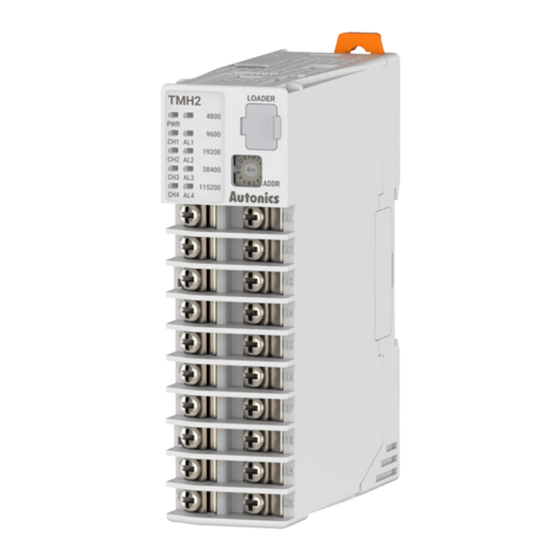
TMH Series
PRODUCT MANUAL
For your safety, read and follow the considerations written in the instruction
manual, other manuals and Autonics website.
The specifications, dimensions, etc are subject to change without notice for product
improvement Some models may be discontinued without notice.
Features
[Common]
• Easy maintenance with detachable body and base terminal
• Power supply and communication with expansion connectors (up to 32 units)
[TMH2/4 Series (Control Module) ]
• Multi-channel (2-channel/4-channel) input and output control: Expandable up to 32
units (64-channels/128-channels)
• 50 ms high-speed sampling rate and ±0.3% measurement accuracy
• Simultaneous heating and cooling control function and auto/manual control mode
(patent: Korea Patent Registration 10-1624105)
[TMHA (Analog Input / Output Option Module) ]
• 4 channels, various input types/temperature ranges/transmission outputs
• 50 ms high-speed sampling rate and ±0.3% measurement accuracy
[TMHE (Digital Input / Alarm Output Option Module) ]
• 8 digital inputs / 8 alarm outputs
[TMHCT (CT Input Option Module) ]
• 8 CT inputs
[TMHC (Communication Modules) ]
• Allows connection of control modules and option modules to master devices
• Connect up to 32 control/option modules per communication model
ᜢ ᜧ ᜣ ᜫ
Safety Considerations
• Observe all 'Safety Considerations' for safe and proper operation to avoid hazards.
• symbol indicates caution due to special circumstances in which hazards may occur.
Warning
Failure to follow instructions may result in serious injury or death
01. Fail-safe device must be installed when using the unit with machinery that
may cause serious injury or substantial economic loss. (e.g. nuclear power
control, medical equipment, ships, vehicles, railways, aircraft, combustion
apparatus, safety equipment, crime/disaster prevention devices, etc.)
Failure to follow this instruction may result in personal injury, economic loss or fire.
02. Do not use the unit in the place where flammable/explosive/corrosive gas,
humidity, direct sunlight, radiant heat, vibration, impact, or salinity may be
present.
Failure to follow this instruction may result in explosion or fire.
03. Install on a device panel to use.
Failure to follow this instruction may result in fire.
04. Do not connect, repair, or inspect the unit while connected to a power
source.
Failure to follow this instruction may result in fire.
05. Check 'Connections' before wiring.
Failure to follow this instruction may result in fire.
06. Do not disassemble or modify the unit.
Failure to follow this instruction may result in fire.
Caution
Failure to follow instructions may result in injury or product damage
01. When connecting the power input and relay output, use AWG 20 (0.50 mm
cable or over and tighten the terminal screw with a tightening torque of 0.74
to 0.90 N·m for screw type.
When connecting the sensor input and communication cable without
dedicated cable, use AWG 24 to 12 cable for screwless type , use AWG 28 to
16 cable for screw type, and tighten the terminal screw with a tightening
torque of 0.74 to 0.90 N·m for screw type.
Failure to follow this instruction may result in fire or malfunction due to contact
failure.
02. Use the unit within the rated specifications.
Failure to follow this instruction may result in fire or product damage
03. Use a dry cloth to clean the unit, and do not use water or organic solvent.
Failure to follow this instruction may result in fire or electric shock.
04. Keep the product away from metal chip, dust, and wire residue which flow
into the unit.
Failure to follow this instruction may result in fire or product damage.
Cautions during Use
• Follow instructions in 'Cautions during Use'. Otherwise, it may cause unexpected
accidents.
• Check the polarity of the terminals before wiring the temperature sensor.
For RTD temperature sensor, wire it as 3-wire type, using cables in same thickness and
length.
For thermocouple (CT) temperature sensor, use the designated compensation wire for
extending wire.
• The connection of this unit should be separated from the power line and high voltage
line in order to prevent inductive noise.
In case of installing power line and input signal line closely, use line filter or varistor at
power line and shielded wire at input signal line.
The connection of this unit should be separated from the power line and high voltage
line in order to prevent inductive noise.
• Do not apply excessive power when connecting or disconnecting the connectors of
the product.
• Switch or circuit breaker should be installed nearby users for convenient control.
• Do not use the unit for other purpose (e.g. voltmeter, ammeter), but temperature
controller.
)
2
Advertisement
Table of Contents

Subscribe to Our Youtube Channel
Related Manuals for Autonics TMH Series


Summary of Contents for Autonics TMH Series
- Page 1 For your safety, read and follow the considerations written in the instruction extending wire. manual, other manuals and Autonics website. • The connection of this unit should be separated from the power line and high voltage The specifications, dimensions, etc are subject to change without notice for product line in order to prevent inductive noise.
-
Page 2: Ordering Information
≈ 129 g Software (packaged) (≈ 222 g) (≈ 236 g) (≈ 204 g) Download the installation file and the manuals from the Autonics website. ■ DAQMaster DAQMaster is comprehensive device management program. It is available for parameter setting, monitoring. -
Page 3: Input Specifications
• When changing the setting value related to communication interface, reboot the device for normal operation. K (CA) .L -200.0 to 1,350.0 -328.0 to 2462.0 • It is recommended to use Autonics communication converter. Please use twisted pair wire, which is suitable for J (IC) .H -200 to 800 -328 to 1,472 RS485 communication. -
Page 4: Installation Method
CT 1 / 3 ■ Option module ■ Precautions TMHA [Analog input / output] • Install the module vertically. • Use end plates (sold separately, not available from Autonics) to fix firmly. Terminal Function 1 Function 2 OUT3 ㎃ B TC, current, +... -
Page 5: Communication Module
-|Transparent Guide|- Configuration Example TMHE [Digital input / Alarm output] Terminal Function TMHA, TMHE and TMHCT are should be used with TMH2/4 control module. Digital1 AL1 OUT Digital input 1 Each module is available to monitoring at DAQMatser via PC loader. Digital input 2 AL2 OUT Digital2... -
Page 6: Unit Descriptions
-|Transparent Guide|- Unit Descriptions - Communication module: TMHC-22L / TMHC-22L-L [Ladderless communication] Internal Ladderless Status Initial power ON Connection Indicator comm. communication • The below is based on screw type model. Flash (red, read Flash (4,800 bps) Flash (green) operation) LED 1 LED 2 (red) Flash (9,600 bps) - Page 7 Sold Separately: CT Connector Cable • When connecting CT connector and CT input terminal, align the concave part and the convex part . Model Cable length CICT4-1 CICT4-3 18, Bansong-ro 513Beon-gil, Haeundae-gu, Busan, Republic of Korea, 48002 www.autonics.com | +82-2-2048-1577 | sales@autonics.com...
Need help?
Do you have a question about the TMH Series and is the answer not in the manual?
Questions and answers