Table of Contents
Advertisement
Quick Links
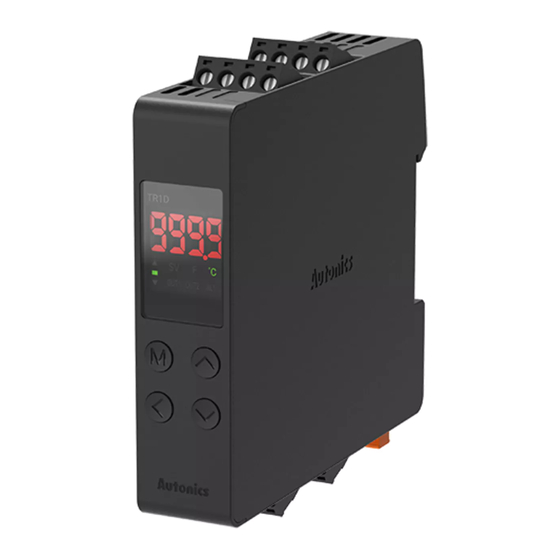
DRW190837AE
Independent Single Display
PID Temperature Controllers
TR1D Series
For your safety, read and follow the considerations written in the instruction
manual, other manuals and Autonics website.
The specifications, dimensions, etc are subject to change without notice for product
improvement Some models may be discontinued without notice.
Features
• Compact, space-saving design with 22.5 mm width size
• 50 ms high-speed sampling and ±0.3% display accuracy
• Simultaneous heating/cooling and automatic/manual control function
• Switch between current output and SSR drive output
• Easy mount on DIN rails (patent)*1
• RS485 communication output model available
- Protocol: Modbus RTU or ASCII
- Communication speed: up to 115,200 bps
• Parameter setting via PC (USB or RS485 communication)
- Comprehensive device management software (DAQMaster) provided
• Heater disconnect alarm function (CT input)
- Current transformer (CT) sold separately: CSTC-E80LN, CSTC-E200LN, CSTS-E80PP
*1 Korea Patent Registration 10-2019-0158569, Korea Design Registration 30-1065663,
China Design Registration 202030164351.2
ᜢ
Screen protection function
Safety Considerations
• Observe all 'Safety Considerations' for safe and proper operation to avoid hazards.
• symbol indicates caution due to special circumstances in which hazards may occur.
Warning
Failure to follow instructions may result in serious injury or death
01. Fail-safe device must be installed when using the unit with machinery that
may cause serious injury or substantial economic loss.(e.g. nuclear power
control, medical equipment, ships, vehicles, railways, aircraft, combustion
apparatus, safety equipment, crime/disaster prevention devices, etc.)
Failure to follow this instruction may result in personal injury, economic loss or fire.
02. Do not use the unit in the place where flammable/explosive/corrosive gas,
high humidity, direct sunlight, radiant heat, vibration, impact or salinity
may be present.
Failure to follow this instruction may result in explosion or fire.
03. Install the unit on DIN rail to use.
Failure to follow this instruction may result in electric shock.
04. Do not connect, repair, or inspect the unit while connected to a power
source.
Failure to follow this instruction may result in fire or electric shock.
05. Check 'Connections' before wiring.
Failure to follow this instruction may result in fire.
06. Do not disassemble or modify the unit.
Failure to follow this instruction may result in fire or electric shock.
Caution
Failure to follow instructions may result in injury or product damage
01. When connecting the power input and relay output, use AWG 20 (0.50 mm
cable or over, and tighten the terminal screw with a tightening torque of 0.74
to 0.90 N m.
When connecting the sensor input and communication cable without
dedicated cable, use AWG 28 to 16 cable and tighten the terminal screw with
a tightening torque of 0.74 to 0.90 N m.
Failure to follow this instruction may result in fire or malfunction due to contact
failure.
02. Use the unit within the rated specifications.
Failure to follow this instruction may result in fire or product damage
03. Use a dry cloth to clean the unit, and do not use water or organic solvent.
Failure to follow this instruction may result in fire or electric shock.
04. Keep the product away from metal chip, dust, and wire residue which flow
into the unit.
Failure to follow this instruction may result in fire or product damage.
Cautions during Use
• Follow instructions in 'Cautions during Use' . Otherwise, it may cause unexpected
accidents.
• Check the polarity of the terminals before wiring the temperature sensor.
For RTD temperature sensor, wire it as 3-wire type, using cables in same thickness and
length. For thermocouple (CT) temperature sensor, use the designated compensation
wire for extending wire.
• Keep away from high voltage lines or power lines to prevent inductive noise .
In case of installing power line and input signal line closely, use line filter or varistor at
power line and shielded wire at input signal line.
Do not use near the equipment which generates strong magnetic force or high
frequency noise.
• Do not apply excessive power when connecting or disconnecting the connectors of
the product.
• Install a power switch or circuit breaker in the easily accessible place for supplying or
disconnecting the power.
• Do not use the unit for other purpose (e.g. voltmeter, ammeter), but temperature
controller.
)
2
Advertisement
Table of Contents

Related Manuals for Autonics TR1D Series


Summary of Contents for Autonics TR1D Series
- Page 1 For your safety, read and follow the considerations written in the instruction • Keep away from high voltage lines or power lines to prevent inductive noise . manual, other manuals and Autonics website. In case of installing power line and input signal line closely, use line filter or varistor at The specifications, dimensions, etc are subject to change without notice for product power line and shielded wire at input signal line.
- Page 2 Parameter: Displays name and setting 1 bit, 2 bit (default) value of parameters. Stop bit 02. Indicator • It is recommended to use Autonics communication converter. Please use twisted pair wire, which is suitable for RS485 communication. Indicator ON contition SV display OUT□...
- Page 3 ○ -cation Dimensions • Unit: mm, For the detailed drawings, follow the Autonics website. Initial Display When Power is ON When power is supplied, after all display will flash for a while, series and model name are displayed sequentially. After input sensor type will flash twice, enter into RUN mode.
- Page 4 -|Transparent Guide|- Installation Method Parameter Setting ■ Mounting on DIN rail • Some parameters are activated/deactivated depending on the model or setting of other parameters. Refer to the descriptions of each item. • Mount the metal part with a spanner so that a large force is not applied to the body. •...
- Page 5 -|Transparent Guide|- ■ Parameter 2 group Function: Alarm Parameter Display Default Setting range Condition Input specification KCaH Refer to 'Input Type and Using Range' Set both alarm operation and alarm option by combining. IN-T Temperature unit ?C ℃, ℉ 88* 8 Each alarm operates individually in two alarm output models.
- Page 6 -|Transparent Guide|- Segment Table 7 Segment 11 Segment 12 Segment 16 Segment 18, Bansong-ro 513Beon-gil, Haeundae-gu, Busan, Republic of Korea, 48002 www.autonics.com | +82-51-519-3232 | sales@autonics.com...
Need help?
Do you have a question about the TR1D Series and is the answer not in the manual?
Questions and answers