Table of Contents
Advertisement
Quick Links
Advertisement
Table of Contents

Related Manuals for Adaptive Recognition Vidar Speed


Summary of Contents for Adaptive Recognition Vidar Speed
- Page 1 Vidar Speed Installation Guide This guide contains an overview of the hardware and required components, suggested scenarios and step-by-step guide for installation, and safety and maintenance instructions. © Copyright Adaptive Recognition Inc. 07.11.2023. All rights reserved.
-
Page 2: Table Of Contents
VIDAR Speed Installation Guide VIDAR SPEED Install Guide Document version: 2023.11.07. Table of Contents Instructional video ............................. 3 Hardware Overview ........................... 4 Required components ..........................5 Recommended installation ........................6 Installation steps............................9 5.1. Power Specification .......................... 9 5.2. Cable Layouts ..........................10 5.3. -
Page 3: Instructional Video
VIDAR Speed Installation Guide INSTRUCTIONAL VIDEO VIDAR ANPR/LPR Camera: Setting the IP Address and Reaching the GUI: In this video, we guide you through connecting the VIDAR ANPR camera to a PC or laptop/centralized router/switch to set it up by covering the following: •... -
Page 4: Hardware Overview
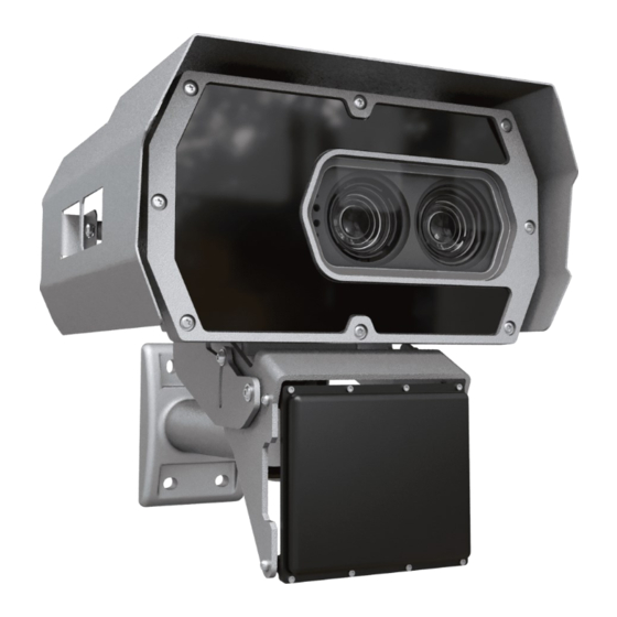
VIDAR Speed Installation Guide HARDWARE OVERVIEW Sunshield Wall bracket Multilane Radar Camera with bracket Red status LED Light sensor Laser Green status LED Built-in- illuminator Camera optics Camera front Page 4/33 REQUESTINFO@ADAPTIVERECOGNITION.COM Adaptive Recognition America Adaptive Recognition Nordic Adaptive Recognition Hungary Adaptive Recognition Singapore WWW.ADAPTIVERECOGNITION.COM... -
Page 5: Required Components
VIDAR Speed Installation Guide REQUIRED COMPONENTS The box contains: • Vidar camera • Bracket • Radar Optional parts: • Power cable • Ethernet cable • Junction Box Assets needed: • Size 3 Allen key + Torx T20 screwdriver • PC to reach web interface •... -
Page 6: Recommended Installation
VIDAR Speed Installation Guide RECOMMENDED INSTALLATION 1. Camera has to mount in horizontal position, do not rotate it any direction! Roll must be 0°. You can check the ROLL on the camera GUI here: (Maintenance > Sensors) Do not be placed in a tunnel, under a bridge, near a billboard, crossing traffic, a bend and a... - Page 7 9. License plates should appear around the center of the image when monitoring 2 lanes (5MPx). 10. If you buy a certified VIDAR Speed all in one, you don't have to physically set it on the RADAR! Page 7/33 REQUESTINFO@ADAPTIVERECOGNITION.COM...
- Page 8 VIDAR Speed Installation Guide 11. Overhead installation - when camera placed above the lane • Height: 7 meters • Between two lanes • Trigger point: 25-30 meters away (from the camera) • Approaching traffic • The radar should not be tilted compared to the Vidar •...
-
Page 9: Installation Steps
VIDAR Speed Installation Guide INSTALLATION STEPS 5.1. POWER SPECIFICATION The required input voltage is model dependent, please use the proper input according to your model! Please consider voltage drop if you use cables! Camera with HDx sensor Camera with FullHD sensor... -
Page 10: Cable Layouts
VIDAR Speed Installation Guide 5.2. CABLE LAYOUTS Ethernet Power I/O (12 pin) Power 4 pos. M12 T coded, Male Input voltage should be connected to AC1 and AC2. Both signals are connected to two pins (a and b) to allow for larger effective cable diameter/two wires for each potential. AC1_a and AC1_b are connected in the device. - Page 11 VIDAR Speed Installation Guide Smartmicro radar: SENSOR CONNECTOR The sensor connector is a 12-pin male (plug) circular bayonet type connector (waterproof IP67, series LF10WBRB-12PD, manufacturer Hirose, Japan). A female counterpart (socket), e.g. LF10WBP- 12S, must be used to connect with the sensor.
-
Page 12: Radar Installation
VIDAR Speed Installation Guide 5.3. RADAR INSTALLATION For a precise measurement the installation geometry must be determined precisely. One must find balance between numerous factors (field of view of radar and camera, trigger distance, character size for LPR, illumination, etc.). The following section will guide through this installation process. -
Page 13: Bracket Details And Sizes
VIDAR Speed Installation Guide 5.4. BRACKET DETAILS AND SIZES To ensure proper mounting of the camera with bracket please use the largest possible fastener (e.g., fastening screw with DIA 8 mm). Only the camera's own screws should be used to fasten the shield and the bracket. Using... - Page 14 VIDAR Speed Installation Guide 5.4.1. General • Use meters and degrees. • All angles follow the usual sign convention: counterclockwise is positive. • The origin of the coordinate system is where the left side of the road meets the installation point.
- Page 15 VIDAR Speed Installation Guide Installation geometry includes the following (not necessarily independent) values: o Y offset of the device, measured from the origin/ side of the road. o Lane width o Elevation angle. Down is negative. o Azimuth angle. Right is negative.
- Page 16 VIDAR Speed Installation Guide 5.4.3. Default values, best practice Hard limits, use these values when designing the site. • Mounting height (H): 4 to 9 m • Elevation angle (E): -9 to -20 deg. • Azimuth angle (A): -15 to 15 deg.
-
Page 17: Installation
VIDAR Speed Installation Guide 5.5. INSTALLATION 5.5.1. A - Initial measurements • A/1: Measure the lane width. Enter the value to LW in two significant figures. • Measure the installation height from the ground up to the radar front. Enter the value to H in two significant figures. - Page 18 VIDAR Speed Installation Guide • B/5: Now check if elevation is within 0.3 degrees of the prescribed value. Correct if necessary. Work in small increments. The measurement is displayed each second. • B/6: Also make sure the displayed roll less than +/- 0.3 degrees.
-
Page 19: Worked Examples
VIDAR Speed Installation Guide 5.6. WORKED EXAMPLES Lanes LW [m] 3.75 3.75 3.75 3.75 3.75 Y [m] H [m] E [deg.] A [deg.] -10.5 -8.3 -8.2 -5.6 TD [m] 20.2 20.6 26.0 25.7 25.9 26.0 Cosine error [%] Angle [deg.]... -
Page 20: Optional Wiring
VIDAR Speed Installation Guide 5.7. OPTIONAL WIRING I/O (12 pin) 12 pos. M12 A coded, Female Connector pinout and wire color coding. Colours refer to those in the supplied standard I/O cable. See Appendix for more details at section 10.2.3 Trigger specifications: •... -
Page 21: Software Requirements
VIDAR Speed Installation Guide SOFTWARE REQUIREMENTS The cameras are developed to operate without any kind of special software. Software requirements: • For network setup, administrator (root) privileges are necessary. • Web browser: Mozilla Firefox 52, Google Chrome 51.X.X.X or later editions. If it is possible, update your browser (Firefox or Chrome) to the newest available version. - Page 22 VIDAR Speed Installation Guide 4. Use the ping command to test the communication with the camera: Windows: C: \>ping -t 192.0.2.3 Linux: username@mylinux:~$ ping 192.0.2.3 5. Soon, the ping package returns: Reply from 192.0.2.3. If not: o first check the Ethernet LEDs at the PC or the switch side o check whether the IP address is set correctly;...
-
Page 23: Safety
VIDAR Speed Installation Guide SAFETY All screws should be hand- tightened! Do not overtighten the screws. Failures due to inappropriate installation void the warranty. The camera must only be installed on a stable surface! For cabling use quality, outdoor-certified cables! Improper cabling causes warranty to void! Water may enter into the camera inside through not properly sealed connectors. -
Page 24: Maintenance / Storage
VIDAR Speed Installation Guide MAINTENANCE / STORAGE The cameras are designed for 24/7/365 work for every weather condition and they do not need special maintenance. Please keep clean the camera front. During the cleaning process, avoid scratching the front cover. -
Page 25: Appendix
VIDAR Speed Installation Guide 10. APPENDIX 10.1. RECOMMENDED POWER SUPPLY Two types of power supply are recommended, one is an AC230V/AC24V transformer, the other is an AC230V/36V DC power supply. Both are suitable for powering a Vidar camera under suitable environmental conditions. - Page 26 VIDAR Speed Installation Guide 10.2.2. Ethernet (8 pos. M12 X coded, Female) ..RJ45 10.2.3. I/O (12 pin) 12 pos. M12 A coded, Female Page 26/33 REQUESTINFO@ADAPTIVERECOGNITION.COM Adaptive Recognition America Adaptive Recognition Nordic Adaptive Recognition Hungary Adaptive Recognition Singapore...
- Page 27 VIDAR Speed Installation Guide 10.2.4. Smartmicro radar: SENSOR CONNECTOR Page 27/33 REQUESTINFO@ADAPTIVERECOGNITION.COM Adaptive Recognition America Adaptive Recognition Nordic Adaptive Recognition Hungary Adaptive Recognition Singapore WWW.ADAPTIVERECOGNITION.COM...
-
Page 28: Adding Alternate Ip Address
VIDAR Speed Installation Guide 10.3. ADDING ALTERNATE IP ADDRESS Windows Vista/Windows 7/Windows 10 1. Click Start and select Control Panel. 2. Open Network and Sharing Center. 3. Click Manage Network Connections on the left side of Network and Sharing Center. -
Page 29: Magnetic Reset
VIDAR Speed Installation Guide 10.4. MAGNETIC RESET These menu entries restart the camera in normal or in recovery mode. If the web interface is not functional (for example due to a lost IP), Recovery Mode may also be entered applying the magnetic reset procedure. -
Page 30: Position Of The Sticker
VIDAR Speed Installation Guide 10.5. POSITION OF THE STICKER Sticker is placed on the bottom of the device. The sticker, indicating the Name, IP address, MAC address and the Serial Number of the camera, can be found on a small metal placket at the bottom of the camera. -
Page 31: Compliances
EN 55032:2015, EN 55024:2010+A1:2015 Declaration of RoHS Compliance for Electrical and Electronic Products: Adaptive Recognition Hungary ("the Company") hereby declares that the VIDAR ANPR camera family placed on the European Community market by the Company after 1st July 2006 are compliant with EC Directive 2002/95/EC on the Restrict of Certain Hazardous Substances in Electrical and Electronic Equipment (commonly known as the EU RoHS Directive.) - Page 32 FCC. Changes or modifications to product not expressly approved by Adaptive Recognition Hungary could void your right to use or operate your product by the FCC.
-
Page 33: Contact Information
Web: adaptiverecognition.com/support/ Adaptive Recognition Hungary Technical Support System (ATSS) is designed to provide you the fastest and most proficient assistance, so you can quickly get back to business. Information regarding your hardware, latest software updates and manuals are easily accessible for customers via our Documents Site (www.adaptiverecognition.com/doc...
Need help?
Do you have a question about the Vidar Speed and is the answer not in the manual?
Questions and answers