
Related Manuals for GW Instek PEL-3000A Series


Summary of Contents for GW Instek PEL-3000A Series
- Page 1 DC Electronic Load PEL-3000A/AH Series USER MANUAL VERSION: 2.00 ISO-9001 CERTIFIED MANUFACTURER...
- Page 2 This manual contains proprietary information, which is protected by copyright. All rights are reserved. No part of this manual may be photocopied, reproduced or translated to another language without prior written consent of Good Will company. The information in this manual was correct at the time of printing. However, Good Will continues to improve products and reserves the rights to change specification, equipment, and maintenance procedures at any time without notice.
-
Page 3: Table Of Contents
Table of Contents Table of Contents SAFETY INSTRUCTIONS ..........3 GETTING STARTED ............8 PEL-3000A/AH Series Introduction ......10 Accessories.............. 12 Appearance .............. 15 First Time Use Instructions ........26 OPERATION ..............51 Basic Operation ............54 Basic Configuration ..........66 Advanced Configuration Settings ...... - Page 4 PEL-3000A/AH series User Manual REMOTE CONTROL ............213 Interface Configuration .......... 214 FAQ ................240 APPENDIX ..............242 Replacing the Dust Filter ........244 Replace the Clock Battery........245 GPIB Installation ........... 246 PEL-3000A/AH Default Settings ......247 Frame Control Connector Contacts ......250 Operating Mode Description .........
-
Page 5: Safety Instructions
SAFETY INSTRUCTIONS AFETY INSTRUCTIONS This chapter contains important safety instructions that you must follow during operation and storage. Read the following before any operation to insure your safety and to keep the instrument in the best possible condition. Safety Symbols These safety symbols may appear in this manual or on the instrument. - Page 6 PEL-3000A/AH series User Manual Safety Guidelines Do not place any heavy object on the General Guideline instrument. Note: Only 2 units can be stacked vertically. CAUTION Ne placez aucun objet lourd sur l'instrument. Remarque: Seules 2 unités peuvent être empilées verticalement.
- Page 7 SAFETY INSTRUCTIONS secteur amovible par des cordons de calibre inadéquat. A suitable supply cord set shall be used with the equipment: - Mains plug: Shall be national approval; - Mains connector: C13 type; - Cable: 1) Length of power supply cord: less than 3 m; 2) Cross-section of conductors: at least 0.75 - Cord type: Shall meet the requirements of IEC 60227 or IEC 60245 (e.g.: H05VV-F, H05RN-F)
- Page 8 PEL-3000A/AH series User Manual If the equipment is used in a manner not specified by the manufacturer, the protection provided by the equipment may be impaired. AC Input voltage range: 100-120VAC/200- Power Supply 240VAC (Max. 90-132VAC/180-250VAC) WARNING Plage de tension d'entrée CA: 100-120VAC/ 200-240VAC (maximum 90-132VAC/180- 250VAC) ...
- Page 9 SAFETY INSTRUCTIONS Disconnect the power cord before cleaning. Cleaning Use a soft cloth dampened in a solution of mild detergent and water. Do not spray any liquid. Do not use chemicals containing harsh material such as benzene, toluene, xylene, and acetone. ...
- Page 10 PEL-3000A/AH series User Manual ETTING STARTED This chapter provides a brief overview of the PEL-3000A/AH, the package contents, instructions for first time use and an introduction to the front panel, rear panel and GUI. PEL-3000A/AH Series Introduction ......10 Model Line Up ................. 10 Main Features ...................
-
Page 11: Getting Started
GETTING STARTED PEL-3211AH Booster Pack ............ 22 Display ....................25 First Time Use Instructions ........26 Rack Mount Kits ................26 Power Up and Self Test ..............29 Load Default Settings ..............29 Setting the Date and Time.............. 30 Load Wiring ..................31 Load Wire Connections .............. -
Page 12: Pel-3000A/Ah Series Introduction
PEL-3000A/AH series User Manual PEL-3000A/AH Series Introduction The PEL-3000A/AH Series is a family of high performance DC electronic loads positioned to test a wide range of different power sources. The DC electronic loads are fully programmable to simulate anything from basic static loads to complex dynamic loads. With the ability to operate independently or in parallel, the PEL- 3000A/AH Series is extremely robust and capable of molding to any test environment. -
Page 13: Main Features
GETTING STARTED Main Features High slew rates of up to 16A/μS Performance (PEL-3111A/AH) for a fast response speed High capacity when used in parallel: 5250W, 1050A(262.5A) (PEL-3111A/AH x 5)/ 9450W, 1890A(472.5A) (PEL-3111A/AH + PEL-3211A/AH x 4) High resolution – 16 bit ... -
Page 14: Accessories
PEL-3000A/AH series User Manual Accessories Standard Part number Description Accessories Quick Start Guide User / Programming manual CD Region Power cord dependent PEL-011 Load input terminal Cover screw PEL-012 Terminal fittings: 2 sets of bolts/nuts/springs/washers (type: M8), Terminal Cover x1 (only for PEL-3000AH series), Monitor Out Cover x 1(only for PEL-3021AH, PEL-3041AH, PEL-3111AH) - Page 15 GETTING STARTED PEL-014 J1/J2 Protection plug x2 (It is installed on the device) 61SF- Front terminal washers 062104N1 Spring washer (M6) x2 GTL-255 300mm Frame Link Cable (for linking units that are stacked).Note that this accessories is optional for the PEL- 3021A/AH or 3041A/AH.
-
Page 16: Package Contents
PEL-3000A/AH series User Manual GTL-259 RS232 cable with DB9 connector to RJ45 GTL-260 RS485 cable with DB9 connector to RJ45 GTL-261 Serial Master Cable + Terminator, 0.5M GTL-262 RS-485 Slave cable Package Contents Check the contents before using the instrument. Opening the box ... -
Page 17: Appearance
GETTING STARTED Appearance Front Panel PEL-3021A/ PEL-3041A Air inlet LCD Display Function keys Power key Main/Local FUNC/File Local Main File FUNC Help/Utility Utility Help Short Short Load Preset Shift Load On/Off CAL. Lock Clear Enter 175W 1.5 - 150V 0 - 35A I MON OUT TRIG OUT Scroll wheel... -
Page 18: Pel-3111A
PEL-3000A/AH series User Manual PEL-3111A Local Main File FUNC Utility Help Short Load Preset Shift 1050W I MON TRIG CAL. Lock 1.5 - 150V Clear Enter 0 - 70A PEL-3111AH Local Main File FUNC Utility Help Short Load Preset Shift CAL. - Page 19 GETTING STARTED Turns the unit on or puts the unit ON/STBY into standby mode. Use the power switch on the rear panel to turn the unit off. Main: Sets the operating mode: Main/Local Main CC, CV, CR, CP mode. Local (Shift + Main): Puts Local the instrument back into Main...
- Page 20 PEL-3000A/AH series User Manual Press the Enter key to select Enter Enter highlighted menu items. Number pad CAL. Lock Clear Number pad: Used to enter numerical values. P0-P9 (Preset + Number keys): Loads one of 10 preset settings. Clear: Clears the current Clear/Lock Lock parameter values.
- Page 21 GETTING STARTED Current monitor BNC terminal: IMON Out Output connector used to monitor the current by outputting a voltage. An output voltage of 1V I MON OUT (10V for PEL-3000AH) corresponds to the full scale current for the H and L ranges. 0.1V (1V for PEL-3000AH) corresponds to the full scale current in the M range.
-
Page 22: Rear Panel
PEL-3000A/AH series User Manual Rear Panel PEL-3021A/ PEL-3041A Frame control Remote Rear panel ports, J1, J2 sense inputs inputs FRAME CONT RS232/ RS485 RS232/RS485 GPIB port 100 - 120 VAC LAN port 200 - 240 VAC 47 - 63 Hz USB device DEVICE port... -
Page 23: Pel-3111A
GETTING STARTED PEL-3111A FRAME CONT DC INPUT 1050 W 1.5 V - 150 V , 210 A RS232/ RS485 100 - 120 VAC 200 - 240 VAC 47 - 63 Hz 190 VA MAX. GPIB DEVICE PEL-3111AH V/I MON OUT FRAME CONT DC INPUT 1050 W... -
Page 24: Pel-3211Ah Booster Pack
PEL-3000A/AH series User Manual PEL-3211AH Booster Pack DC INPUT 2100 W FRAME CONT 5 V - 800 V , 105 A 100 - 120 VAC 200 - 240 VAC 47 - 63 Hz 230 VA MAX. The USB B, RS232C and GPIB port are used for RS232/RS485 remote control. - Page 25 GETTING STARTED Monitor Out ports J3 J3: The J3 connector is assigned to current and voltage monitor out. Variable Resistor The variable resistors are used to adjust the full CC/CR/CV/CP scale and offset setting for the input value of the external control sources such as voltage or resistance.
- Page 26 PEL-3000A/AH series User Manual Power Socket: Power Socket 100-120V, 200-240V 47-63Hz. Turns the unit on/off. Power Switch LAN port Ethernet port for controlling the PEL-3000A/AH remotely.
-
Page 27: Display
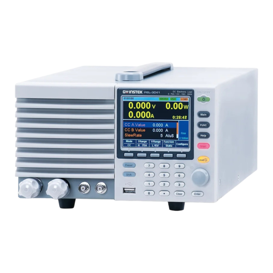
GETTING STARTED Display Mainframe status panel Date 01/May/2021 RS232 LOAD 0. 00 0.00 Measurement area 0.0000 CC A Value 0. 0000 setting Operation area CC B Value 0. 0000 status Fine SlewRate 140 . 00 mA/ us panel A Value Mode I Range V Range... -
Page 28: First Time Use Instructions
PEL-3000A/AH series User Manual First Time Use Instructions Use the procedures below when first using the PEL-3000A/AH to install the rack mount kit, power up the instrument, set the internal clock, restore the factory default settings and check the firmware version. - Page 29 GETTING STARTED GRA-413-J (JIS standard) GRA-414-E (EIA standard)
- Page 30 PEL-3000A/AH series User Manual GRA-414-J (JIS standard)
-
Page 31: Power Up And Self Test
GETTING STARTED Power Up and Self Test Steps 1. Insert the AC power cord into the power socket. 2. Turn the external power switch on. (O → —) 3. If the unit doesn’t turn on, press the On/Standby key. The ON/STBY key will go from standby (red) to on (green). -
Page 32: Setting The Date And Time
PEL-3000A/AH series User Manual RS232 LOAD 01/May/2021 Load Default Setup 8.75A 800V Static Warning!!! Pressing F2 Again will Recall The Default Settings! A Value Media Factory Save Recall Default Default Setting the Date and Time Description The date and time settings are used to time-stamp files when saving files. -
Page 33: Load Wiring
GETTING STARTED Load Wiring Wire Gauge Before connecting the unit to a power source, the considerations wire gauge must be taken into account. Load wires must be large enough to resist overheating when a short-circuit condition occurs as well as to maintain a good regulation. - Page 34 PEL-3000A/AH series User Manual 1.02362 20.9428 0.91186 26.40728 0.8126 33.292 0.7239 41.984 Load Line When using the PEL-3000A/AH load generator, Inductance voltage drop and voltage generated due to load Considerations line inductance and current change must be taken into account. Extreme changes in voltage may exceed the minimum or maximum voltage limits.
- Page 35 GETTING STARTED twist the positive and negative load wires together. 3. Current change can be limited by limiting the slew rate or response speed when switching in CR and CC mode. “Twisted pair” will be shown on any connection diagram where the load wires should be twisted together.
-
Page 36: Load Wire Connections
PEL-3000A/AH series User Manual Load Wire Connections Description The PEL-3000A/AH has input terminals on both the front and rear panels. Follow the procedures below for all load connections. Please adhere to the following precautions to ensure your safety and to protect the unit from damage. -
Page 37: Using The Front Panel Input Terminals
GETTING STARTED Using the Front Panel Input Terminals Description The front panel input terminals feature polarity- distinct caps and accept M6 sized crimped terminals. The front panel input terminals on the PEL-3000A/AH Caution are physically connected to the rear panel terminals. Steps 1. -
Page 38: Using The Rear Panel Input Terminals
PEL-3000A/AH series User Manual Using the Rear Panel Input Terminals Description The rear panel input terminals accept up to M8- sized crimped terminals. The rear terminals come with a load input terminal cover for safety. The front panel input terminals on the PEL-3000A/AH Caution are physically connected to the rear panel terminals. -
Page 39: Using The Terminal Cover (Pel-011)
GETTING STARTED Using the Terminal Cover (PEL-011) Description The rear panel terminal cover should be used to prevent electric shock. The rear panel terminal covers should always be used when connecting a load to the rear panel terminals. As the front panel and rear panel terminals are physically connected, the terminal cover should also be used as a safety measure when a DUT is connected to the front... - Page 40 PEL-3000A/AH series User Manual Detail 4. Use your thumb to slide the terminal covers shut, as shown in the diagram below. 5. When the top and bottom covers are flush, reinsert the screw that was removed in step 1.
-
Page 41: Using The Terminal Cover (Pel-013)
GETTING STARTED Using the Terminal Cover (PEL-013) Description The flexible rear panel terminal cover should be used when the load wiring becomes too thick to be used with the PEL-011 terminal cover. This is especially true when using the load generators in parallel. -
Page 42: Using The Terminal Cover
Ensure the power is off before making any Caution connections to the booster pack. Install the terminal cover as shown in the picture below (for PEL-3000AH series). Install the terminal cover as shown in the picture below (for PEL-3000A series). -
Page 43: Using The Monitor Out Cover (Only For Pel-3021Ah, Pel-3041Ah, Pel-3111Ah)
GETTING STARTED Using the Monitor Out Cover (Only for PEL-3021AH, PEL-3041AH, PEL-3111AH) Description After connection is finished, please lock monitor out cover to avoid electric shock when using the monitor out ports. Ensure the power is off before making any Caution connections to the booster pack. -
Page 44: Remote Sense
PEL-3000A/AH series User Manual Remote Sense Description Remote sense can be used to help compensate for long cable length. The longer the cable, the higher the potential resistance and inductance, therefore a short cable is best. Twisting the cable can help reduce induced inductance and using the Vsense terminals compensates the voltage drop seen across the load leads, especially leads with higher... -
Page 45: Firmware Update
Firmware Update Description The PEL-3000A/AH allows the firmware to be updated by end-users. Before using the PEL- 3000A/AH, please check the GW Instek website or ask your local distributor for the latest firmware. System version Before updating the firmware, please check the firmware version. - Page 46 PEL-3000A/AH series User Manual Update Firmware 1. Insert a USB drive into the USB port. Ensure the USB drive has the firmware file located in the root directory. File FUNC Shift 2. Press 3. Select USB with the Media[F1] soft-key. 4.
-
Page 47: Conventions
GETTING STARTED Conventions The following conventions are used throughout the user manual. Read the conventions below for a basic grasp of how to operate the PEL-3000A/AH menu system using the front panel keys. Soft Menu keys The F1 to F5 function keys at the bottom of the display correspond directly to the soft-menu keys on top. - Page 48 PEL-3000A/AH series User Manual Toggle Parameter Function/Item or State Mode Parameter or State This type of soft-menu icon has the function/item on the top of the label and the selected setting or mode on the bottom of the label. Repeatedly press the associated function key (F1- F5) to cycle through each setting.
- Page 49 GETTING STARTED Number pad Scroll wheel CAL. Lock Enter key Clear Enter 1. Use the scroll wheel to move the cursor to the desired parameter. A scroll bar is shown when there are additional parameters off-screen. 01/May/2021 RS232 LOAD 0 .
- Page 50 PEL-3000A/AH series User Manual Clearing a Value* *When editing a parameter with the number pad, pressing the key will restore the Clear parameter to the previous value. Using the Scroll **To edit a parameter using the scroll wheel, Wheel to Edit a simply turn the scroll wheel.
- Page 51 0.000 0.00 GETTING STARTED 0.000 01/May/2021 RS232 LOAD Highlighted 0.00 0.00 parameter 0.0000 CC A Value 0.0000 Cursor CC A Value 0.000 CC B Value 1.0000 Mode Cursor SlewRate 140.00 mA/ us Indicator A Value CC B Value 1.000 Mode I Range V Range Function...
-
Page 52: Help Menu
PEL-3000A/AH series User Manual Help Menu When any function key has been pressed or when a menu has been opened, the HELP key can be used to display a detailed description. Help Selection 1. Press any function key or soft-menu key. 2. -
Page 53: Operation
OPERATION PERATION Basic Operation ............54 CC Mode ................... 54 CR Mode ................... 56 CR Units ..................57 CV Mode ................... 58 CP Mode .................... 59 +CV Mode ..................61 Turning on the Load ............... 62 Shorting the Load ................62 Safety Short ................ - Page 54 PEL-3000A/AH series User Manual Step Mode Configuration ............... 81 Protection Settings ..........83 OCP ....................83 OPP ....................84 UVP ....................85 UVP Ring Time ................86 OVP ....................88 UnReg ....................89 Para ..................... 90 RVP ....................91 System Settings ............92 Sound Settings ..................
- Page 55 OPERATION Select a Function ................114 Turning on the Load with the Selected Function ....116 Complete Ring Time ..............117 NSEQ Timer .................. 118 Program ..............120 Program Overview ................. 120 Create a Program ................122 Create a Program Chain ..............125 Running a Program or Chain ............
-
Page 56: Basic Operation
PEL-3000A/AH series User Manual Basic Operation The PEL-3000A/AH supports 7 main operating modes: CC, CC+CV; CR, CR+CV; CP, CP+CV CC Mode Description In Constant Current Mode the load units will sink the amount of current programmed. Regardless of the voltage, the current will stay the same. For more details on CC mode, please see the Appendix on page 256. - Page 57 OPERATION 6. Set the current level parameters using the scroll wheel and number pad. For Static mode, set CC A Value and/or CC B Value. For Dynamic mode, set Level1 and Level2. The maximum and minimum current levels depend on the selected ranges.
-
Page 58: Cr Mode
PEL-3000A/AH series User Manual CR Mode Description In Constant Resistance Mode, the unit will maintain a constant resistive load by varying the current. CR mode uses ohms, Ω (resistance) or siemens, S (conductance) for the setting units. For more details on CR mode, see the appendix on page 257. -
Page 59: Cr Units
OPERATION such as the slew rate, and switching function settings. See page 66 for details. Display RS232 LOAD 01/May/2021 0.000 0.00 Active setting Conductance/ 0.0000 Resistance settings Ω CR A Value 0.54422 Ω CR B Value 0.54422 Voltage Mode Fine SlewRate 14.000 mA/uS... -
Page 60: Cv Mode
PEL-3000A/AH series User Manual CV Mode Description In Constant Voltage Mode, the unit will maintain a constant voltage. In CV mode you set the constant voltage level. For more details on CV mode, see the appendix on page 260. If you change the mode or the range when the load is Warning already on, the load will be turned off automatically. -
Page 61: Cp Mode
OPERATION Display RS232 LOAD 01/May/2021 0.000 0.00 Active setting 0.0000 Voltage Current setting settings CV A Value 80.000 CV B Value 80.000 Voltage Mode Fine range A Value Mode I Range V Range Response Configure H 8.75A L 80V Slow Current range Basic CV mode configuration is complete. - Page 62 PEL-3000A/AH series User Manual 6. Set the power level parameters using the scroll wheel and number pad. For Static mode, set CP A Value and/or CP B Value. For Dynamic mode, set Level1 and Level2. The maximum and minimum power levels depend on the selected current range.
-
Page 63: Cv Mode
OPERATION +CV Mode Description +CV mode can be added to CC, CR and CP mode. The +CV settings apply to all applicable modes. Operation 1. Make sure the load is off. 2. Press and select to Mode, I Range and Main V Range. -
Page 64: Turning On The Load
PEL-3000A/AH series User Manual Turning on the Load Description 1. The load can be turned on and off by pressing Load key. The Load key will turn orange when the load is “on”. The LOAD icon in the Main Frame status panel will turn orange when the load is on. -
Page 65: Safety Short
OPERATION CR mode. Setting the voltage to the minimum value in CV mode. Setting the power to the maximum value in CP mode. When the load is shorted, the external controller also sends a short signal. See page 201 for usage details. -
Page 66: Short Key Configuration
PEL-3000A/AH series User Manual Operation 1. Press > Configure[F5] > Other[F2] and Main set the Short Safety. When set to OFF, the load can be shorted at anytime. When set to ON, the load can only be shorted when the load is already on. -
Page 67: Short Function Enable/Disable
OPERATION Short Function Enable/Disable Description The short key can be disabled to prevent the operator accidentally shorting the load. Operation 1. Press > Configure[F5] > Other[F2] and Main set the Short Function. When set to OFF, the Short key is disabled and all short configuration options in the Main>Configure>Other menu are also disabled. -
Page 68: Basic Configuration
PEL-3000A/AH series User Manual Basic Configuration The basic configuration settings are the common configuration settings that are used for each operating mode. After selecting a basic operating mode (CC, CR, CV or CP mode), the slew rate, switching function, response rate and other common parameters should be configured. - Page 69 OPERATION Dynamic Mode Level Level 2 Level 1 Timer1 Timer2 Timer1 Time Dynamic mode is not available for CV mode. Note Operation 1. Make sure the load is off. Main 2. Press 3. Select Dynamic or Static mode with the Function[F4] soft-key.
-
Page 70: Select The Display Units For Dynamic Mode Levels
PEL-3000A/AH series User Manual Display: RS232 LOAD 01/May/2021 Static Mode 0.00 0.00 A Value 0.0000 B Value CP A Value 0.00 Active setting CP B Value 0.00 Static mode Fine OFF V A Value Mode I Range V Range Function Configure H 8.75A H 800V... -
Page 71: Select The Switching Time Configuration For Dynamic Mode
OPERATION Operation 1. Make sure the load is off. 2. Press > Configure[F5] > Other[F2] and Main set the Dyna. Level setting. Range: Value, Percent Display: 01/May/2021 RS232 LOAD Percent Setting 0.000 0.00 Set level 0.0000 % from the Set value 1.00 Level 50.0... -
Page 72: Slewrate
PEL-3000A/AH series User Manual Slew Rate Description The current slew rate can be set for CC and CR mode. The slew rate setting is used to limit the change in current when switching. For static mode, only a single slew rate can be set. Operation 1. -
Page 73: Cv, +Cv Mode Response Speed
OPERATION CV, +CV Mode Response Speed Description The response speed setting is the response speed for the negative feedback control of the load current when used in CV, +CV mode. Response speed settings are only applicable to CV, +CV mode. ... -
Page 74: Cc, Cr And Cp Mode Response Speed
PEL-3000A/AH series User Manual Display 01/May/2021 RS232 LOAD 0.000 0.00 0.0000 CV A Value 80.000 CV B Value 80.000 Response Fine setting A Value Mode I Range V Range Response Configure H 8.75A L 80V Slow CC, CR and CP Mode Response Speed Description By default, the “normal current response”... -
Page 75: Advanced Configuration Settings
Rise voltage Rise current Time Soft Start= OFF Input I Rise current Rise voltage Time Operation 1. Press > Configure[F5] > Other[F2] and Main set the Soft Start time. Range: OFF, 1-200ms for PEL-3000A series OFF, 3-200ms for PEL-3000AH series... -
Page 76: Von Voltage Settings
PEL-3000A/AH series User Manual Von Voltage Settings Von Voltage Description The Von Voltage is the threshold voltage at which the load module will start to sink current. Von voltage V out Load on Time PEL-3000A Time Operation 1. Press > Configure[F5] > Other[F2] and Main set the Von Voltage level. -
Page 77: Von Latch
OPERATION Von Latch Description When Von Latch is set to ON, the load will continue to sink current after being “latched”, even if the voltage drops below the Von Voltage threshold level. When Von Latch is set to OFF, the load will turn off when the voltage drops below the Von Voltage threshold level. -
Page 78: Von Delay
PEL-3000A/AH series User Manual Von Delay Description Von Delay is the amount of time the unit will wait before turning the load on after the Von Voltage threshold has been latched. This will prevent overshoot current from affecting the Von Voltage threshold. -
Page 79: Cut Off Time
OPERATION Display RS232 LOAD 01/May/2021 0.000 0.00 Elapsed time 0.0000 0:00:05 Level1 0.00 Cut Off Time Description The Cut Off Time function will turn the load off after a set-amount of time. After the load has been turned off, a popup screen will display the voltage level when the load was turned off. -
Page 80: Auto Load Configuration
PEL-3000A/AH series User Manual Auto Load Configuration Description The PEL-3000A/AH can be configured to automatically load the last program, normal sequence, fast sequence or load setting at startup. By default, this setting is disabled. Operation Utility Help Shift 1. Press >... -
Page 81: Load Off (Mode) And Load Off (Range)
OPERATION Load Off (Mode) and Load Off (Range) Description By default the load will automatically turn off when the either the operating mode (CC, CV, CR, CP) or the range (I range, V range) is changed. To allow the load to stay on when the operating mode is changed, set the Load Off (Mode) setting to OFF. -
Page 82: Step Resolution Configuration
PEL-3000A/AH series User Manual Step Resolution Configuration There are two different ways to set the resolution when using the scroll wheel to edit parameters. Step Mode and Cursor Mode. Step Mode is the default method. Only one mode can be active at a time; When one mode is active, the other mode is deactivated. -
Page 83: Step Mode Configuration
OPERATION Step Mode Configuration Description When set to Step Mode, the voltage, current, resistance and power settings can have the step resolution configured. The step resolution refers to the step resolution of the coarse adjustment for these settings. The fine adjustment cannot be configured. - Page 84 PEL-3000A/AH series User Manual Operation 1. Press > Configure[F5] > Next Menu[F4] Main > Knob[F2] and make sure the Status setting is set to Step. 2. Set the desired step resolution settings. (The step resolution settings are only available when Status=Step (coarse/fine)) ...
-
Page 85: Protection Settings
OPERATION Protection Settings The Protection settings are used to prevent damage to the unit or the DUT by excessive current, voltage or power. An alarm is generated and a message is displayed on the screen when a protection setting is tripped. When an alarm is activated, the load is turned off (or limited), and the ALARM STATUS pin of the J1 connector on the rear panel (pin 16) turns on (open collector output by a photocoupler). -
Page 86: Opp
PEL-3000A/AH series User Manual Display Alarm message RS232 LOAD 01/Oct/2017 when OCP is 8.653 0.4327 OCP indicator set to Load Off 50.006 OCP Alarm Please Press Enter CV A Value 80.000 To Clear Alarm CV B Value 80.000 Fine A Value Mode I Range V Range... -
Page 87: Uvp
OPERATION Display Alarm message RS232 LOAD 01/Oct/2017 when OPP is 8.653 0.4327 OPP indicator set to Load Off 50.006 OPP Alarm Please Press Enter CV A Value 80.000 To Clear Alarm CV B Value 80.000 Fine A Value Mode I Range V Range Response Configure... -
Page 88: Uvp Ring Time
PEL-3000A/AH series User Manual Display Alarm message RS232 LOAD 01/Oct/2017 when UVP is 0.4327 8.653 UVP indicator set to Load Off 50.006 UVP Alarm Please Press Enter CV A Value 80.000 To Clear Alarm CV B Value 80.000 Fine A Value Mode I Range V Range... - Page 89 OPERATION and message will remain on screen until the message is cleared. 4. If the voltage rises back above the UVP level, the UVP indicator will be cleared from the display but the buzzer will continue to sound until the UVP Ring Time has elapsed and the message will remain until it has been cleared.
-
Page 90: Ovp
PEL-3000A/AH series User Manual Description If the OVP is tripped, the PEL-3000A/AH will turn off the load. The OVP levels can be set from 0V to 10% higher than the rating voltage. Operation 1. Press > Configure[F5] > Protection[F1] Main and set the OVP Level. -
Page 91: Unreg
OPERATION UnReg Description The UnReg error message will appear on the display when the electronic load is operating in an unregulated state. The UnReg indicator will appear on the display Alarm when the set load is inadequate for the source. ... -
Page 92: Para
PEL-3000A/AH series User Manual Para Description The Para error message will appear on the display when the PEL-3000A/AH is used in parallel and if an error is produced. The Para error message indicates one of the Alarm following possible conditions: UnReg, ROCP, OTP. -
Page 93: Rvp
OPERATION Description If the RVP is tripped, the PEL-3000AH series will turn off the load. The RVP error message indicates when the Alarm terminal voltage is negative. The Enter key must be pressed to clear the alarm message. Display Alarm message RS232... -
Page 94: System Settings
PEL-3000A/AH series User Manual System Settings The following section covers a number or miscellaneous system settings such as: Speaker settings Display settings Alarm tone settings Input control settings Language settings Input/output trigger settings All system settings are accessible in the Utility menu. Sound Settings Speaker Settings Description... -
Page 95: Alarm Tone Settings
OPERATION Alarm Tone Settings Description The alarm tone for the unit can be turned on or off in the utility menu. The alarm tone can be set separately for the protection settings (OCP, OPP, UVP, OVP), Go-NoGo testing or for when the unit is operating in an unregulated state (see page 89). -
Page 96: Control Settings
PEL-3000A/AH series User Manual Control Settings Description The Knob Type setting determines if values are updated immediately as they are edited or if they are only updated after the Enter key is pressed. The Updated setting is applicable for when the load is already on and the user wishes to change the set values (current, voltage, etc.) in realtime. -
Page 97: Trigger Out Width
OPERATION Operation Utility Help Shift 1. Press > Other[F5]. 2. Set the Trig In Delay setting. Range: 0.01~100ms, Default: 0.01ms Trigger Out Width Description The Trigger Out Width setting sets the trigger output signal’s pulse width. Operation Utility Help Shift 1. -
Page 98: Measure Period
PEL-3000A/AH series User Manual Measure Period The Measure Period setting is used to set the Description update rate of the measurement. The setting has three modes. They are 20ms, 200ms and 1000ms. The default mode for Measure Period setting is 200ms. -
Page 99: Go-Nogo
OPERATION Go-NoGo The Go-NoGo configuration is used to create pass/fail limits on the voltage or current input. If the voltage/current exceeds the pass/fail limits, an alarm will be output. The Go-NoGo configuration can be used with the Program function to create complex pass/fail tests. Setting the Go-NoGo Limits Description The Go-NoGo setting limits can be set as either... -
Page 100: Running A Go-Nogo Test
PEL-3000A/AH series User Manual 5. Set the Delay Time. The delay time setting will delay activating the Go-NoGo testing by a specified amount of time. The delay setting can compensate for startup oscillation and other instabilities during startup. Delay Time 0.0-1.0 seconds (0.1s resolution ) When the Main settings are saved or recalled, the Go-... - Page 101 OPERATION Display: RS232 LOAD 01/Oct/2018 Test result 0.000 0.00 0.0000 SPEC test = ON SPEC Level1 0.00 Level2 0.00...
-
Page 102: Save Recall
PEL-3000A/AH series User Manual Save Recall The PEL-3000A/AH can save and recall system settings, preset data, memory data, Go-NoGo settings as well as normal and fast sequences to internal memory or to USB. File Structure Description The PEL-3000A/AH file system can save files to internal memory (Media|Memory) and external memory (Media|USB). -
Page 103: File Types
OPERATION active preset setting. For normal and fast sequences however, files can be saved or recalled directly to/from USB memory. File Types Memory Data Memory data contains general settings and is used for creating programs. Memory Data contains the operating mode, range, response and Go/NoGo settings. -
Page 104: Saving Files To Internal Memory
PEL-3000A/AH series User Manual Internal Format None External Format model no_file no.F example: 3021A/AH_00.F Saving Files to Internal Memory Description When saving Memory, Setup or Preset Data to internal memory, the currently active setting is saved to one of the internal memory slots. Memory Data has 256 memory slots, Setup Data has 100 memory slots and Preset Data has 10 memory slots. - Page 105 OPERATION Data Type: Memory Data, Setup Data, Preset Data 4. Select which internal memory location to save the file. Memory: M001 - M256 Setup Memory: 1 - 100 Preset: P0 - P9 5. Press Save[F3] to save. Save Ok will be displayed when the save has been completed.
-
Page 106: Saving Files To Usb Memory
PEL-3000A/AH series User Manual Saving Files to USB Memory Description When saving files to USB memory, all the memory locations from the selected data type are saved as a single file to the USB file path directory. Memory Data Media | Memory Media | USB Example M001... - Page 107 OPERATION 5. Select Save File and choose a save filename. Turn the scroll wheel to increase/decrease the file number. Memory: Model_file number.M Setup Memory: Model_file number.S Preset: Model_file number.P NSeq: Model_file number.N FSeq: Model_file number.F 6. Press Save[F3] to save. ...
-
Page 108: Recalling Files From Internal Memory
PEL-3000A/AH series User Manual Recalling Files from Internal Memory Description When recalling Memory, Setup or Preset Data from the internal memory slots, the recalled file becomes the active setting. Memory Data has 256 memory slots, Setup Data has 100 memory slots and Preset Data has 10 memory slots. -
Page 109: Recalling Files From Usb Memory
OPERATION Memory: M001 - M256 Setup Memory: 1 - 100 Preset: P0 - P9 5. Press Recall[F4] to recall. For Memory Data and Preset Data, a popup window will appear. Press the key to Enter confirm the recall. Normal Sequence and Fast Sequence data cannot be Note recalled from or saved to an internal memory slot. - Page 110 PEL-3000A/AH series User Manual Display 01/May/2021 RS232 LOAD Recall file type 87.5mA Data Type Memory Save File 3021AH_01.M Static Recall File 3021AH_02.M Recall file Path: usb: USB file name path A Value Media File Save Recall Utility Operation 1. Insert a USB drive into the USB port. File FUNC Shift...
-
Page 111: Recall Memory Safety Setting
OPERATION File Utilities 7. Press File Utility[F5] to access the file utility. See page 109 for details. Change the USB path. Rename files or create directories. If “Machine Type Error” is displayed it indicates that Caution the file that you are trying to recall originated from a different model. - Page 112 PEL-3000A/AH series User Manual Display RS232 LOAD 01/May/2021 USB path cursor Path: usb:\Test Folder1 16-Feb-17 13:46 Folder2 18-Feb-17 11:16 Folder3 19-Feb-17 08:32 175H_01.M 01-Mar-17 10:12 175H_02.M 03-Mar-17 13:13 175H_03.M 23-Mar-17 09:02 3 folder(s), 15 file(s) Previous Select Rename Delete Folder Menu Access the File 1.
-
Page 113: Preset
OPERATION Preset The Preset key is used to save and recall preset settings from the front panel quickly. The presets have the same contents as memory data, this includes the operating mode, range, configuration settings and Go-NoGo settings. Quick Preset Save Description The current settings can be saved to P0 - P9 using the Preset key and the number pad. -
Page 114: Default Settings
PEL-3000A/AH series User Manual Default Settings Factory Default Settings Description The factory default settings can be recalled at any time. See page 247 for a list of the factory default settings. Operation File FUNC Shift 1. Press 2. Select Default with the Media[F1] soft-key. 3. -
Page 115: Function Menu
FUNCTION MENU UNCTION MENU Function Menu Overview ........114 Select a Function ................114 Turning on the Load with the Selected Function ....116 Complete Ring Time ..............117 NSEQ Timer .................. 118 Program ..............120 Program Overview ................. 120 Create a Program ................122 Create a Program Chain .............. -
Page 116: Function Menu Overview
PEL-3000A/AH series User Manual Function Menu Overview The Function menu can be used as a quick access hub to the Program, Normal Sequence, Fast Sequence, OCP, OPP or BATT menus. It is also used to set Function specific settings: Function Select. ... - Page 117 FUNCTION MENU turn on or choose to turn off the last function. Range OFF, PROG, NSEQ, FSEQ, OCP After a function is selected, it is then “turned Note on”. PROG NSEQ FSEQ BATT MPPT will appear at the top of the display when the selected function is on.
-
Page 118: Turning On The Load With The Selected Function
PEL-3000A/AH series User Manual Turning on the Load with the Selected Function Description 1. When a function is turned on, the load can be turned on (with the selected function) by Shift Load pressing . This can be done at anytime. ... -
Page 119: Complete Ring Time
FUNCTION MENU Complete Ring Time Description The Complete Ring Time function turns the alarm on for a user-set amount of time after a program, sequence or OCP function has finished. Function Select RS232 01/May/2021 PROG Screen FUNCTION Function Select PROG Complete Ring Time NSEQ Timer Elapsed... -
Page 120: Nseq Timer
PEL-3000A/AH series User Manual NSEQ Timer Description The NSEQ Timer setting determines whether the timer for the Normal Sequence function displays the elapsed time or the remaining time for both the current step and the overall test time for the sequence. - Page 121 FUNCTION MENU Display example RS232 NSEQ 01/May/2021 0.000 0.00 0.0000 0:00:05 Run N.Seq. Seq. No: Elapsed or remaining time Step 0003 for the total test time 0:00:05 Loop: 0001 Elapsed or remaining time for the current step Continue When the total test time is >1000 hours, then the total Note test time will always be displayed as the elapsed time.
-
Page 122: Program
PEL-3000A/AH series User Manual Program The PEL-3000A/AH can create programs that are designed to step- through up to 16 pre-set load operations. The program function is a powerful tool that can allow you to perform a number of different operations in succession. ... - Page 123 FUNCTION MENU program chains. Program chains need not be executed in order. There are 16 steps to a program. There are up to 16 programs to a chain. STEP 01 STEP 02 PROGRAM 1 STEP 16 STEP 01 STEP 02 PROGRAM 2 STEP 16...
-
Page 124: Create A Program
PEL-3000A/AH series User Manual P/F End Test Time (fixed) P/F Start Test Time (fixed) 0.06s P/F Time 0.04s Short-Time Start of Step On-Time Off-Time End of Step Step test time Create a Program Before creating a program, the settings for each step Note must first be created and saved to internal memory (M001-M256). - Page 125 FUNCTION MENU 4. Select Memory and select which memory location to load for the selected step. Settings loaded from the memory location will be used for the selected step. The same memory location can be used for multiple steps. Memory M001 - M256 5.
- Page 126 PEL-3000A/AH series User Manual P/F-Time Off, 0.0 - 119.9 seconds 9. Set the Short-Time in seconds. Has the same action as pressing the short key. See page 62 for details about shorting the load. Short-Time Off, 0.1 seconds - On-Time 10.
-
Page 127: Create A Program Chain
FUNCTION MENU Create a Program Chain Before creating a program chain, make sure a number Note of programs have already been saved. These will be used to create the program chain. Chain Setting Starting program RS232 LOAD 01/Oct/2017 Display Overview for the chain Program Chain Set Start... -
Page 128: Running A Program Or Chain
PEL-3000A/AH series User Manual 5. Press Save to save the program chain to internal memory. 6. Pressing Recall Default[F4] will reset the chain to the default settings. See page 247 for details. Recall Default[F4] will essentially clear the program chain. Running a Program or Chain Description A program or program chain is run the same way... - Page 129 FUNCTION MENU Display: RS232 PROG 01/May/2021 Program/Chain 0.000 0.00 Running 0.0000 Program number that is currently running. Run Program Program No: Step(Memory) 01(001) Go-NoGo result Step that is Continue for the step currently running. Memory number of current step. Display: 01/May/2021 RS232 PROG...
-
Page 130: Sequence
PEL-3000A/AH series User Manual Sequence The PEL-3000A/AH supports both programs and sequences. The essential difference between programs and sequences is that programs can use different operating modes for each step while sequences use the same operating mode throughout the whole sequence. - Page 131 FUNCTION MENU STEP 01 STEP 02 Start Sequence Sequence 1 STEP N STEP 01 STEP 02 Sequence 2 STEP N STEP 01 STEP 02 Sequence 10 STEP N Description Normal Sequence configuration is split into Timing Edit configuration and Data Edit configuration.
- Page 132 PEL-3000A/AH series User Manual 12 characters Memo A user-created note for the currently selected sequence. CC, CR, CV, CP Mode Operating mode for the sequence. +CV mode is supported. ILVL Range Low I range, low V range IMVL Middle I range, low V range IHVL High I range, low V range ILVH...
- Page 133 FUNCTION MENU Value The current, voltage, power or resistance setting for the selected operating mode. 0.05ms - 999h:59m Sets the step time for the Time selected step. ON, OFF Load Turns the load on or off for the selected step. ON, OFF RAMP When turned on the current...
-
Page 134: Timing Edit Configuration
PEL-3000A/AH series User Manual TRIG OUT = ON amplitude Time Start of step TRIG OUT ON, OFF PAUSE Pause: Inserts a pause at the end of the step. When paused, the unit will pause at the end of the step current/voltage/resistance/po wer level. - Page 135 FUNCTION MENU Start: S01 - S10 3. Select a Seq. No. and select which sequence to edit. Seq. No.: S01 - S10 4. Set the following parameters for the currently selected sequence. See page 128 for details on each parameter. ...
-
Page 136: Data Edit Configuration
PEL-3000A/AH series User Manual Data Edit Configuration Data Edit Display Total number of steps Active step number RS232 LOAD 01/Oct/2017 Data Edit for Normal Sequences Step: 0001 0001 Value: 0.000 Time: 000 H: 00 M: 00 S 0.05ms LOAD: TRIG OUT RAMP: PAUSE: Step settings... -
Page 137: Running A Normal Sequence
FUNCTION MENU Value Time LOAD RAMP TRIG OUT PAUSE 6. If you wish to edit a previously inserted point/step, use the Step parameter. Steps can only be selected after they have already been inserted. Steps 0001 - 1000 7. - Page 138 PEL-3000A/AH series User Manual will appear at the top of the display when NSEQ N. Seq. is On. The Normal Sequence function can also be turned on from the FUNC menu. See page 114 for details. 3. Turn the load on by pressing Shift Load ...
- Page 139 FUNCTION MENU Display: Current step readback Sequence/Chain measurements RS232 NSEQ 01/May/2021 Running Elapsed or 0.000 0.00 remaining time for the total test time 0.0000 0:00:46 Run N.Seq. Seq. No: Step 0003 0:00:05 Current sequence, Loop: 0001 step and loop Step elapsed/ number Continue remaining time...
-
Page 140: Fast Sequence Overview
PEL-3000A/AH series User Manual Fast Sequence Overview Description A fast sequence is comprised of a user-defined number of steps that can be executed at a high frequency. Unlike normal sequences, each step in a fast sequence has the same execution time (time base). - Page 141 FUNCTION MENU Description Fast Sequence configuration is split into Timing Edit configuration and Data Edit configuration. Timing Edit configuration is used to configure all the settings that are common to all the steps of the fast sequence. This includes settings such as the mode, range, loops and time base.
- Page 142 PEL-3000A/AH series User Manual 0001 - 1000 RPTSTEP Last step number (0001-1000) per loop 0.025 - 600ms Time Base Sets the step execution time. Data Edit Each step in a fast sequence contains the following Overview setting parameters: Setting Range Description Setting 0001 - 1000...
- Page 143 FUNCTION MENU The Fill Function can be used before or after points are added to the fast sequence. Before: Will pre-fill each value within the fill range when a new step is added. After: Will post-fill each value within the fill range.
-
Page 144: Timing Edit Configuration
PEL-3000A/AH series User Manual Timing Edit Configuration Edit Timing 01/May/2021 RS232 LOAD Display Timing Edit for Fast Sequence Memo: Mode: Last Load: Range: ILVL Last 0.00000 A Loop: Infinity RPTSTEP 0004 Time Base: 600.00 ms F. Seq. Edit Previous Sequence Menu Sequence settings Operation... -
Page 145: Data Edit Configuration
FUNCTION MENU Go to Data Edit to edit the steps used in the Fast Sequence. Page 143. Go to Running a Fast Sequence to run the fast sequence. Page 145. Data Edit Configuration Data Edit Display Total number of steps Active step number RS232 LOAD... - Page 146 PEL-3000A/AH series User Manual sequence. Every-time Insert Point is pressed the Step parameter is incremented. The newly inserted “point” becomes the active step. 3. Set the following parameters for the currently selected step. See page 137 for configuration details.
-
Page 147: Running A Fast Sequence
FUNCTION MENU Go to Running a Fast Sequence to run the fast sequence. Page 145. Running a Fast Sequence Description Unlike a normal static or dynamic load, a Fast Sequence load is turned on by pressing the Shift and Load keys. Operation FUNC 1. - Page 148 PEL-3000A/AH series User Manual Display: 01/May/2021 RS232 FSEQ Fast Sequence 7.498 0.0825 Running 11.001 Current step number Run F.Seq. Step 0023 Loop: 0001 Current loop number...
-
Page 149: Ocp Test Automation
FUNCTION MENU OCP Test Automation The OCP test function creates an automatic test to Background test the OCP of power supply products. This test will test to see when the over current protection of a power supply is tripped and return the measurements for the voltage and current when the over current protection was tripped. - Page 150 PEL-3000A/AH series User Manual OCP. No Selects one of 12 OCP test setup Parameters memories. Memo A user-created note for the currently selected OCP function. Range High(CC Mode High), Middle(CC Mode Middle) and Low(CC Mode Low) Start Current Starting current value for the test. (Start C) End Current The current value that will end...
- Page 151 FUNCTION MENU Trig Voltage Sets the trigger to a level needed (Trig_V) to see when the power supply OCP has been triggered. When the power supply OCP has been triggered, its voltage output will reset. The voltage trigger level is used to test to see if the voltage output has been reset.
- Page 152 PEL-3000A/AH series User Manual End C Step_C Step_T Delay Trig_V Last_C 4. Press the Save[F3] to save the selected test setup. Start OCP 5. Press OCP[F1] to turn the OCP function on if it is off.
- Page 153 FUNCTION MENU Results: Power Source Indicating power supply OCP tripped OCP was tripped. RS232 01/May/2021 7.498 0.00 0.0000 OCP Test Set Curr: Fetch Volt: Current: 6.91 2.000 6.92 1.500 2.500A 6.91 1.000 Step current setting on the load when the power supply’s OCP was tripped.
- Page 154 PEL-3000A/AH series User Manual Power Source RS232 FSEQ 03/May/2021 Config Error 0.00 0.00 0.000 OCP Test Set Curr: Fetch Volt: Config Error Config Error indicates that upon starting the power supply voltage is less than the Trig V voltage. Config Error indicates that the power supply voltage is less than the Trig V voltage setting after the test has started.
- Page 155 FUNCTION MENU Press Save [F3] to save the data log to USB flash drive. The file name should be RESULTxx.CSV. The file RESULTxx.CSV can be opened in the computer. The maximum amount of data to be recorded in the data log is 65536. If data exceeds this limit, the extra data won’t be recorded.
-
Page 156: Opp Test Automation
PEL-3000A/AH series User Manual OPP Test Automation The OPP test function creates an automatic test to Background test the OPP of power supply products. This test will test to see when the over power protection of a power supply is tripped and return the measurements for the voltage and current when the over power protection was tripped. - Page 157 FUNCTION MENU A user-created note for the Memo currently selected OPP function. Range High(CP Mode High) Middle(CP Mode Middle) Low(CP Mode Low) Start Watt Starting watt value for the test. (Start W) End Watt The watt value that will end the (End W) test.
- Page 158 PEL-3000A/AH series User Manual Last Watt Sets the final watt value after (Last W) OPP has been tripped. This is the steady-state watt draw after the OPP has been tripped. Panel operation FUNC 1. Press > Next Manu[F5]. > OPP[F1]. 01/May/2021 NO.: OPP Function...
- Page 159 FUNCTION MENU Start OPP 5. Press OPP[F1] to turn the OPP function on if it is off. 6. The OPP function can be started by turning the load on by pressing Shift Load The test watt will increase from the Start W value to the End W value in steps according to the Step W value, until the test has finished.
- Page 160 PEL-3000A/AH series User Manual Power Source 01/May/2021 OPP tripped 50.61 50.72 4.81 10.530 0:00:07 OPP Test Fetch Watt: Fetch Volt: 60.76 4.79 Watt: 50.71 4.82 40.57 4.83 50.71 W 30.40 4.85 TEST Exit Save Result The OPP Test will return the current setting of the last step when the power supply’s OPP was tripped.
- Page 161 FUNCTION MENU Power Source 01/May/2021 Config Error 4.90 0.00 0.000 OPP Test Fetch Watt: Fetch Volt: Config Error 0.00 4.91 Exit Config Error indicates that the power supply voltage is less than the Trig V voltage setting after the test has started.
- Page 162 PEL-3000A/AH series User Manual Plug in USB flash drive and press Save [F3] to save the waveform picture. Press Esc [F1] to exit the waveform view mode. Press Save [F3] to save the data log to USB flash drive. The file name should be RESULTxx.CSV. The file RESULTxx.CSV can be opened in the computer.
-
Page 163: Batt Test Automation
FUNCTION MENU BATT Test Automation The BATT test function creates an automatic test to Background test the discharge of Battery products. The test will discharge in a fixed mode (CC, CR, CP) and will end after a defined stop point (stop voltage, stop time, stop AH) has been detected. - Page 164 PEL-3000A/AH series User Manual Begin Discharge Stop Volt Current Setting CR mode SlewRate = SlewRate ? Stop Time Stop AH Begin Discharge Stop Volt Current Setting CP mode SlewRate = SlewRate ? Stop Time Stop AH BATT No. Selects one of 12 BATT test setup Parameters memories.
- Page 165 FUNCTION MENU ILVH(I range low, V range high) IMVH(I range middle, V range high) IHVH(I range high, V range high) Setting Sets the values corresponding to the defined discharging mode (CC mode in A, CR mode in mS and CP mode in W).
- Page 166 PEL-3000A/AH series User Manual 01/May/2021 BATT BATT Function BATT NO.: Memo: No Memo Mode: Range: IHVH Setting: 5.0000 A BATT Previous Menu BATT 01/May/2021 BATT Function SlewRate 25.000 mA/us SlewRate 25.000 mA/us Stop Volt: 3.00 V Stop Time: Stop AH: 0.20Ah BATT Previous...
- Page 167 FUNCTION MENU BATT No. SlewRate? Memo Stop Volt Mode Stop Time Range Stop AH Setting Datalog timer SlewRate= 3. Press the Save[F3] to save the selected test setup. Start BATT 1.
- Page 168 PEL-3000A/AH series User Manual save the waveform picture. Press Esc [F1] to exit the waveform view mode. Press Save [F3] to save the data log to USB flash drive. The file name should be RESULTxx.CSV. The file RESULTxx.CSV can be opened in the computer.
- Page 169 FUNCTION MENU Results: BATT 01/May/2021 Battery stop 50.61 0.00 2.95 Voltage or stop time or stop AH 0.000 tripped 0.0418 0.1778 Complete Discharging: CC, IHVH, 5.0000 A Stop Volt: 3.00V TEST Exit Save Result 01/May/2021 BATT 50.61 0.00 4.92 0.000 0.0832 0.4077 Complete Discharging:...
- Page 170 PEL-3000A/AH series User Manual In addition to the BATT Function settings as described Note above, the Stop Volt voltage settings must also be set according to the output characteristics of the DUT.
-
Page 171: Mppt
FUNCTION MENU MPPT The MPPT (Maximum Power Point Tracking) Background function of PEL-3000A/AH series can perform IV, PV characteristics and Pmax tracking tests of solar panels. The firmware (Ver.1.32 or later for PEL-3000A and Note Ver.1.08 or later for PEL-3000AH series) is compatible with this extended function. - Page 172 PEL-3000A/AH series User Manual MPPT No. Set one of 12 test patterns. Parameters Memo A user-created note for the currently selected BATT function. Mode Select a discharge operation mode. (CC, CV) Range Set the voltage and current range. ILVL(I range low, V range low) IMVL(I range middle, V range low) IHVL(I range high, V range low) ILVH(I range low, V range high)
- Page 173 FUNCTION MENU Start C Response appears only in CC (Start Current) mode. Set the start current value and its range is from 0A to the maximum of the setting current. End C Response appears only in CC (End Current) mode. Set the end current value and its range is from 0A to the maximum of the setting current.
- Page 174 PEL-3000A/AH series User Manual RS232 01/May/2021 LOAD MPPT Function Sweep Range: Value Start V: 0.000 V End V: 0.000 V Step V: 0.000 V Step Time: 0.000 V MPPT Previous Edit Time Set Tracking Menu 01/May/2021 RS232 LOAD MPPT Function Start V: 0.000 V End V:...
-
Page 175: Edit Tracking Of Mppt Function
FUNCTION MENU RS232 01/May/2021 LOAD MPPT Function Sweep Range: Value Start C: 0.00000 A End C: 0.00000 A Step C: 0.00000 A Step Time: 0.00 s MPPT Previous Edit Time Set Tracking Menu 2. Set the following parameters. MPPT No. ... -
Page 176: Auto Load Of Mppt Function
PEL-3000A/AH series User Manual Time Interval) 1m to 60m). Redetecting can also be used when the maximum power point is two. Measure Interval Set the measurement time (Measurement interval (1.0s to 60.0s). Time Interval) Panel operation FUNC 1. Press > Next Manu[F5] > MPPT[F4] Edit Tracking[F2]. - Page 177 FUNCTION MENU Set the start and stop date, start Enable and stop time. Panel operation FUNC 1. Press > Next Manu[F5] > MPPT[F4] Time Set[F3]. RS232 01/May/2021 LOAD Auto Load of MPPT function Auto Load on/off: Disable Start Time: 00/ 00/ 00, 00: 00: 00 Stop Time05/ 00/ 00, 00: 200: 00 Exit 01/May/2021...
- Page 178 PEL-3000A/AH series User Manual RS232 01/May/2021 LOAD Auto Load of MPPT function Auto Load on/off: Only Stop Start Time: 17/ 06/ 01, 08: 00: 00 Stop Time: 17/ 06/ 01, 01: 00: 00 Exit RS232 01/May/2021 LOAD Auto Load of MPPT function Auto Load on/off: Enable Start Time: 17/ 06/ 01, 08: 00: 00...
- Page 179 FUNCTION MENU Example: MPPT RS232 MPPT 01/May/2021 Function running 50.61 0.466 0.071 1.2197 0:00:00 Detect Pmax: Fetch Volt: Fetch Watt: Running... 0.305 0.385 0.043 0.054 Pmax: 0001 0.043 0.054 MPPT: 0000 0.043 0.054 RS232 MPPT 01/May/2021 50.61 0.644 0.512 1.2596 0:00:03 Hill Climb: Fetch Volt:...
- Page 180 PEL-3000A/AH series User Manual To save the test result data, press Save [F3]. The maximum amount of data to be recorded in the data log is 65536. If data exceeds this limit, the extra data won’t be recorded. To see the graph of the maximum power point tracking test, presss Detect P'max [F1].
-
Page 181: Data File Of Test Result
FUNCTION MENU Data file of test result Test result data is saved as a CSV file. Background Example: Test conditions and results file <DATE> Date of test <Pmax Detection Method> Settings contents for Pmax detection (in CV mode). <Hill Climbing Method Setting contents of the hill climbing Tracking>... - Page 182 PEL-3000A/AH series User Manual Example: Results file of IV and PV characteristics test < PMAX DETECTION Pmax detection results. RESULTS > (1) Start Time Test start time (2) MAX No. Data number when Pmax is maximum (3) MAX Voltage Voltage value when Pmax is maximum (4) MAX Current Current value when Pmax is maximum...
- Page 183 FUNCTION MENU CURR(A) Measured current value POWER(W) Measured power value Example: Results file of MPPT test (1) Start Time Test start time (2) Stop Time Test end time Measured voltage value VOLT(V) Measured current value CURR(A) Measured power value POWER(W)
-
Page 184: External Control
PEL-3000A/AH series User Manual XTERNAL CONTROL Analog Control ............183 J1 Connector Overview ..............183 J3 port (PEL-3021AH/PEL-3041AH/PEL-3111AH) ... 184 External Voltage Control - Overview ........185 External Voltage Control – Operation ........ 186 Adjust offset and full scale with variable resistor (PEL-3021AH/ PEL-3041AH/ PEL-3111AH) .... -
Page 185: Analog Control
EXTERNAL CONTROL Analog Control The Analog Control subsection describes how to use the J1 Frame Control Connector for voltage or resistance control. The J2 connector, located under the J1 connector is used for parallel control. See page 250 for details about the J1 and J2 connectors. J1 Connector Overview Description The J1 External Control Connector is a standard... -
Page 186: J3 Port (Pel-3021Ah/Pel-3041Ah/Pel-3111Ah)
PEL-3000A/AH series User Manual J3 port (PEL-3021AH/PEL-3041AH/PEL-3111AH) Description Use wire of 24 to 28 AWG to connect with J3 port. Please peel the coating of a wire approximately 10mm and then insert the wire to the terminal hole while pushing the button on the terminal hole of the J3. -
Page 187: External Voltage Control - Overview
EXTERNAL CONTROL External Voltage Control - Overview Background External voltage control of the CC, CR, CV, CP and Cx+CP mode is accomplished using the J1 connector on the rear panel. An input voltage of 0- 10V corresponds to 0% - 100% of the rated current (CC mode), rated voltage (CV mode), or rated power (CP mode). -
Page 188: External Voltage Control - Operation
PEL-3000A/AH series User Manual The input impedance for external voltage control is Note 10kΩ. Use a stable voltage supply for the external voltage control. When using external voltage control, make sure no Caution more than ±11V is applied across pins 1 and 3. Exceeding this voltage could damage the PEL- 3000A/AH. - Page 189 EXTERNAL CONTROL Under EXTernal Control, the panel or remote Note command will no more control the unit. The front panel will show the icon “EXT”. In brief, just use: EXT OFF to disable and turn it back to normal control, or applying Load Default Setting to prevent electric shock, ensure the cover for the J3.
- Page 190 PEL-3000A/AH series User Manual CR Mode Input conductance = rated conductance × (external voltage/10) Input Conductance Rated Conductance External Voltage CV Mode Input voltage = rated voltage × (external voltage/10) Cx+CV Mode Input Voltage Rated Voltage External Voltage CP Mode Input power = rated power ×...
- Page 191 EXTERNAL CONTROL See page 56 for CR mode. See page 58 for CV mode. See page 59 for CP mode. 5. Press > Configure [F5] > Next Menu [F4] Main > External [F3]. 6. Set the Control parameter to V. ...
-
Page 192: Adjust Offset And Full Scale With Variable Resistor (Pel-3021Ah/ Pel-3041Ah/ Pel-3111Ah)
PEL-3000A/AH series User Manual Adjust offset and full scale with variable resistor (PEL-3021AH/ PEL-3041AH/ PEL-3111AH) Variable Resistor in rear panel CC/CR/CV/CP 1. Apply a voltage of 1V to pin J1-1 based on the Operation level of pin J1-3. CC, CR, CV, CP Mode 2. -
Page 193: External Resistance Control - Overview
EXTERNAL CONTROL level of pin J1-3. 6. Turn VR4 with screwdriver to adjust the value to 10% of the rating in each +CV mode. Readjustment is needed when you use a different Note voltage range. External Resistance Control - Overview Background External resistance control of the CC, CR, CV and CP modes is accomplished using the J1 connector... -
Page 194: External Resistance Control - Operation
PEL-3000A/AH series User Manual Use resistors with minimum residual resistance of Note 50Ω or less. Note for proportional control: Do not use swtiches that switch between fixed resistances. Please use continuously variable resistors. External Resistance Control – Operation Description External resistance control can be used to control the current, voltage, resistance and power for CC, CR, CV and CP modes. - Page 195 EXTERNAL CONTROL CC Mode Proportional Control: Input current = rated current × (external resistance/10). Inverse Control: Input current = rated current × (1 - external resistance/10). Inverse control Input Current Proportional control Rated Current External Resistance 0Ω 10kΩ CR Mode Proportional Control: Input conductance = rated conductance ×...
- Page 196 PEL-3000A/AH series User Manual CV Mode Proportional Control: Input voltage = rated voltage × (external resistance/10). Inverse Control: Input voltage = rated voltage × (1 - external resistance/10). Inverse control Input Voltage Proportional control Rated Voltage External Resistance 0Ω 10kΩ CP Mode Proportional Control: Input power = rated power ×...
-
Page 197: Adjust Offset And Full Scale With Variable Resistor (Pel-3021Ah/ Pel-3041Ah/ Pel-3111Ah)
EXTERNAL CONTROL 2. Connect the external resistance across pins 1 and 3 of the J1 connector. 3. Turn the power on the PEL-3000A/AH. 4. Set the operating mode and range. See page 54 for CC mode. See page 56 for CR mode. ... -
Page 198: Turning The Load On Using External Control
PEL-3000A/AH series User Manual 5. Connect 1kΩ between J1-1 and J1-3. 6. Turn VR2 with screwdriver to adjust the value to 10% of the rating in each the operating mode. Readjustment is needed when you use a different Note operating mode, current range or voltage range. Inverse control 1. - Page 199 EXTERNAL CONTROL PEL-3000A/AH Switch 10kΩ Analog connector A COM Example The LoadOn IN setting determines whether the load is turned on when the external switch is closed (low) or open (high). High LoadOn In = High High LoadOn In = Low Load off Load Load on...
-
Page 200: Load On/Off Status
PEL-3000A/AH series User Manual Load On/Off Status Description Pin 13 (Load On Status) of the J1 connector is used to monitor the load status (on or off). Pin out The Load On Status pin is a photo-coupled open- collector output. Photocoupler input: 30V max, 8mA, max. -
Page 201: I Range Status
EXTERNAL CONTROL Pin Inputs Pins 8 and 9 of the J1 connector are internally pulled up to 5V with a 10kΩ resistor when open. When closed, pin 8 and 9 are pulled down to the A COM ground level. PEL-3000A/AH Switches 10kΩ... -
Page 202: External Trigger Signal
PEL-3000A/AH series User Manual External Trigger Signal Description Pins 11 and 12 of the J1 connector are the trigger signal inputs. The trigger signal is used to resume a sequence after a pause. This action is useful to synchronize the execution of a sequence with another device. -
Page 203: Alarm Status
EXTERNAL CONTROL PEL-3000A/AH Switch 10kΩ Analog connector A COM Alarm Status Description Pins 16 and 17 of the J1 connector are used to monitor whether the alarm is on or off. Pin out The Alarm Status pin is a photo-coupled open- collector output. -
Page 204: Monitor Signal Output
PEL-3000A/AH series User Manual External PEL-3000A/AH relay driver connector Input Terminals The external relay driver is not a standard accessory. Note Please provide your own external relay and driver circuit. Monitor Signal Output Trigger Signal Output Description The trigger output signal is generated every time a switching operation is performed (i.e., Dynamic mode) or when a Fast or Normal Sequence is executed and the TRIG OUT parameter is enabled. -
Page 205: Current Monitor Output For Pel-3000A
EXTERNAL CONTROL Current Monitor Output for PEL-3000A series Description The voltage output from the IMON OUT terminal and from the IMON pin on the J1 connector is used to represent the current input level. The voltage range used to represent the full scale... -
Page 206: Current Monitor Output For Pel-3000Ah
PEL-3000A/AH series User Manual Current Monitor Output for PEL-3000AH series Description The voltage output from the IMON OUT terminal and from the IMON pin on the J3 connector is used to represent the current input level. The voltage range used to represent the full scale current range from the IMON OUT terminal and from the IMON pin on the J3 connector depends on the current range settings. -
Page 207: Voltage Monitor Output (Pel-3021Ah/Pel-3041Ah/Pel-3111Ah)
EXTERNAL CONTROL Voltage Monitor Output (PEL-3021AH/PEL-3041AH/PEL-3111AH) Description The voltage output from the VMON OUT terminal and from the VMON pin on the J3 connector is used to represent the current input level. The V Range used to represent the full scale current range from the VMON OUT terminal and from the VMON pin on the J3 connector depends on the current range settings. -
Page 208: Parallel Operation
PEL-3000A/AH series User Manual Parallel Operation The PEL-3000A/AH series can be connected in parallel to increase the total power capacity of a single unit. The PEL-3000A/AH series can operate with up to 5 units in parallel. A single unit is designated as a master unit and any other connected units as slaves. -
Page 209: Parallel Capacity, Pel-3021Ah, Pel-3041Ah, Pel-3111Ah
EXTERNAL CONTROL Parallel Capacity, PEL-3021AH, PEL-3041AH, PEL-3111AH Model Single Unit 2 Units 3 Units 4 Units 5 Units PEL-3021AH 800V 800V 800V 800V 800V 8.75A 17.5A 26.25A 43.75A 175W 350W 525W 700W 875W PEL-3041AH 800V 800V 800V 800V 800V 17.5A 52.5A 87.5A 350W... -
Page 210: Parallel Capacity, Pel-3211Ah
PEL-3000A/AH series User Manual Parallel Capacity, PEL-3211AH Model No. of Total Sink Current Total Power Units PEL-3111AH+ PEL-3111AH + PEL-3211AH PEL-3211AH PEL-3111AH: 800V 52.5A N/A Master 800V 105A 157.5A 3150W 800V 210A 262.5A 5250W PEL-3211AH: Slave Boosters 800V 315A 367.5A 7350W 800V 420A 472.5A... - Page 211 EXTERNAL CONTROL MASTER Load wiring Sense wiring SLAVE 1 SLAVE 2 SLAVE 3 Only the rear terminals can be used for parallel Cautions connections. Make sure all connections are correct before turning on the load. Incorrect connections could damage the units.
-
Page 212: Configuration
PEL-3000A/AH series User Manual Configuration Description When using the multiple units in parallel all the basic settings are adopted from the master unit. Operation 1. Make sure all load units are turned off. 2. Make sure the DUT is turned off. 3. - Page 213 EXTERNAL CONTROL Ethernet LOAD 11/May/2021 Configure 105A 800V Operation Master Static Parallel Booster A Value Previous Parallel Knob External Menu 6. On the slave units, press > Configure Main [F5] > Next Menu [F4] > Parallel[F1] > and set Operation to Slave. ...
-
Page 214: Turning The Load On
PEL-3000A/AH series User Manual Turning the Load On Description Operating the PEL-3000A/AH Series in parallel mode is the same as for single units. When using the units in parallel, the load line Note inductance could be increased or the stability of the units could be reduced. -
Page 215: Remote Control
EMOTE CONTROL This chapter describes basic configuration of IEEE488.2 based remote control. For a command list, refer to the programming manual, downloadable from GW Instek website, www.gwinstek.com Interface Configuration ...........214 Configure to USB Remote Interface .......... 214 Configure GPIB Interface ............214 Configure RS232 or RS485 ............ -
Page 216: Interface Configuration
PEL-3000A/AH series User Manual Interface Configuration Configure to USB Remote Interface PC side connector Type A, host configuration Rear panel Type B, slave PEL-3000A/AH side connector 2.0 (full speed) Speed USB CDC ACM USB Class Before USB can be used for remote control, it is Note necessary to install the PEL-3000A/AH USB device driver, located on the accompanying User Manual CD. - Page 217 REMOTE CONTROL GPIB address 0-30 GPIB constraints Maximum 15 devices altogether, 20m cable length, 2m between each device Unique address assigned to each device At least 2/3 of the devices turned On No loop or parallel connection Pin Assignment Signal Signal...
-
Page 218: Configure Rs232 Or Rs485
PEL-3000A/AH series User Manual Configure RS232 or RS485 RS232C Connector RJ-45 Configuration Baud Rate 2400/ 4800/ 9600/ 19200/ 38400/ 57600/ 115200 Data Bits 7bits/ 8bits Stop Bits 1bit/ 2bits Parity None/ Odd/ Even Operation 1. Connect an RS232 or RS485 series RS232 RS485 cable from the PC to the Remote... -
Page 219: Set The Uart Settings
Overview The PEL-3000A/AH series uses the IN & OUT ports for UART communication coupled with RS232 (GW Instek Part number: GTL-259) or RS485 adapters (GW Instek part number: GTL-260). The pin outs for the adapters are shown below. RS232 cable with... - Page 220 PEL-3000A/AH series User Manual Connection diagram GTL-260 Diagram of Intermediate connector Intermediate Intermediate connector connector from 8 Pin (Male) 8 Pin (Female) GTL-259 or GTL- Pin No. Name Pin No. Name Remarks 260 connection Housing Shield Case Shield kit. TXD - TXD - Internal paralleled by 120 ohm TXD +...
-
Page 221: Multiple Unit Connection
REMOTE CONTROL Multiple Unit Connection The PEL-3000A/AH can have up to 16 units daisy-chained together using the 8 pin connectors (IN OUT ports) on the rear panel. The first unit in the chain is remotely connected to a PC using RS485. Each subsequent unit is daisy-chained to the next using a RS485 local bus. - Page 222 PEL-3000A/AH series User Manual 3. Power up all units. Utility 4. Press > Interface[F3] and Help Shift set the Interface setting to UART> Mode and set the Mode to RS485. 5. Set the addresses and mode of all units using UART menu.
-
Page 223: Rs232 Or Rs485/Usb Remote Control Function Check
Serial number, and Firmware version in the following format. GW-INSTEK,PEL-3000A/AH, XXXXXXXXXXXX, V.X.X.X.X Manufacturer: GW-INSTEK Model number : PEL-3000A/AH Serial number : XXXXXXXXXXXX Firmware version : V.X.X.X For further details, please see the programming Note manual, available on the GW Instek web site @ www.gwinstek.com. -
Page 224: Using Realterm To Establish A Remote Connection
PEL-3000A/AH series User Manual Using Realterm to Establish a Remote Connection Background Realterm is a terminal program that can be used to communicate with a device attached to the serial port of a PC or via an emulated serial port via USB. The following instructions apply to version 2.0.0.70. - Page 225 REMOTE CONTROL 5. Start Realterm on the PC as an administrator. Click: Start menu>All Programs>RealTerm>realterm Tip: to run as an administrator, you can right click the Realterm icon in the Windows Start menu and select the Run as Administrator option. 6.
- Page 226 PEL-3000A/AH series User Manual 8. Click on the Send tab. In the EOL configuration, check on the +CR and +LF check boxes. Enter the query: *idn? Click on Send ASCII. 9. The terminal display will return the following: GW, PEL-3XXXA/AH,EXXXXXXX,VX.XX.XXX (manufacturer, model, serial number, version) 10.
-
Page 227: Gpib Function Check
GPIB functionality. See the National Instrument website, http://www.ni.com for details. For further details, please see the programming Note manual, available on the GW Instek web site @ www.gwinstek.com. Operation 1. Start the NI Measurement and Automation Explorer (MAX) program. Using Windows, press: Start>All Programs>National... - Page 228 PEL-3000A/AH series User Manual 4. In the Connected Instruments panel the PEL- 3000A/AH should be detected as Instrument 0 with the address the same as that configured on the PEL-3000A/AH. 5. Double click the Instrument 0 icon. 6. Click on Communicate with Instrument. 7.
- Page 229 REMOTE CONTROL GW,PEL-3041AH, xxxxxxxx,Vxx 9. The function check is complete. For USB CDC function check, please refer to the Note section “RS232 and USB CDC function check” on page...
-
Page 230: Configuring Ethernet Connection
PEL-3000A/AH series User Manual Configuring Ethernet Connection When using Ethernet a number of parameters Background need to be set. These include DHCP On/Off, IP Address, Subnet Mask and Gateway. When setting Ethernet parameters, ensure they match that of the network. DHCP On/Off Parameters... - Page 231 REMOTE CONTROL 4. Press F3 (Interface Menu). LOAD 15/Dec/2022 Configure Interface 105A 800V A Value System Time Set Other Load Interface Info 5. If the Interface mode is not Ethernet, use the Selector knob to edit Interface. 6. Choose Ethernet. Interface Ethernet 7.
- Page 232 PEL-3000A/AH series User Manual 9. Use the Selector knob to edit DHCP, IP Address, Subnet Mask and Gateway setting. If the DHCP set to ON, the IP Address, Subnet Mask Note and Gateway settings will be configured by the DHCP Server of the network automatically.
-
Page 233: Socket Server Function Check
REMOTE CONTROL Socket Server Function Check Background To test the socket server functionality, National Instruments Measurement and Automation Explorer can be used. This program is available on the NI website, www.ni.com., via a search for the VISA Run-time Engine page, or “downloads” at the following URL, http://www.ni.com/visa/ Requirements Operating System: Windows XP, 7, 8, 10... - Page 234 PEL-3000A/AH series User Manual 5. Enter the IP address and the port number of the PEL-3000A/AH. The port number is fixed at 2268. 6. Click the Validate button. 7. A popup will appear if a connection is successfully established. If not,check the Load device IP address configuare.
- Page 235 REMOTE CONTROL 8. Click the Finish button. 9. You can see the network device is setup successful. Click Open VISA Test Panel. 10. In the TCP/IP Settings page. You can see the information of TCP/IP.
- Page 236 PEL-3000A/AH series User Manual 11. Click on I/O Settings. 12. Make sure the Enable Termination Character check box is checked, and the terminal character is \n (Value: xA). 13. Click Apply Changes. 14. Click the Input/Output icon. 15. Enter *IDN?\n in the Select or Enter Command dialog box if it is not already.
- Page 237 17. The *IDN?\n query will return the Manufacturer, model name, serial number and firmware version in the dialog box. GW Instek,PEL-3000A/AH,00000001, V108\n GW Instek,PEL-3000A/AH,00000001, V108\n 18. You can key in the command “:SYST:ERR\n” 19. Click the Query button. You will get the return...
- Page 238 PEL-3000A/AH series User Manual...
-
Page 239: Web Server Function Check
REMOTE CONTROL Web Server Function Check The web server allows you to check the function Functionality settings of the PEL-3000A/AH. check Enter the IP address of the PEL-3000A/AH in a web browser. The web browser interface appears. The web browser interface allows you to access the following: ... - Page 240 PEL-3000A/AH series User Manual 2. You can click the Figure of dimension to see the device dimensions information. 3. You can click the Operating area to see the Load operating area.
- Page 241 REMOTE CONTROL...
-
Page 242: Faq
PEL-3000A/AH series User Manual • The load voltage indicated on the load module is below expected. • The front panel keys are not working. • The load won’t turn on. • The performance does not match the specification The load voltage indicated on the load module is below expected. Ensure the load leads are as short as possible, twisted and use the appropriate wire gauge. - Page 243 For more information, contact your local dealer or GW Instek at www.gwinstek.com / marketing@goodwill.com.
- Page 244 PEL-3000A/AH series User Manual PPENDIX Replacing the Dust Filter ........244 Replace the Clock Battery........245 GPIB Installation ........... 246 PEL-3000A/AH Default Settings ......247 Frame Control Connector Contacts ......250 J1 Connector ................... 250 J2 Connector ................... 252 Monitor Out ports J3 (PEL-3021AH/PEL-3041AH/PEL-3111AH) ......
-
Page 245: Appendix
APPENDIX Front Panel BNC Connector ............278 General..................... 278 PEL-3000AH Specifications ........280 Rating (Master / Slave) ..............280 Rating (Booster / Slave) ............... 280 CC Mode ..................281 CR Mode ..................282 CV Mode ..................282 CP Mode ..................283 Slew Rate .................. -
Page 246: Replacing The Dust Filter
PEL-3000A/AH to malfunction. Procedure 1. Turn the PEL-3000A/AH off completely at the rear panel power switch. 2. Gently lift the grill up from the bottom. 3. Remove the filter from the grill and replace with GW Instek part number: PEL-010. -
Page 247: Replace The Clock Battery
APPENDIX Replace the Clock Battery Background The system clock keeps time using a user- replaceable battery. The battery should be replaced approximately every 3 years. Battery type: CR2032 Procedure 1. Turn off the PEL-3000A/AH and remove the case. First remove the handle by carefully removing the plastic tabs and then unscrewing the two screws connecting the handle to the case. -
Page 248: Gpib Installation
PEL-3000A/AH series User Manual GPIB Installation Background GPIB is an optional extra. The following instructions describe how to install the optional GPIB card if necessary. Procedure 1. Turn off the PEL-3000A/AH. 2. Remove the two screws holding the cover on the option bay. -
Page 249: Pel-3000A/Ah Default Settings
APPENDIX PEL-3000A/AH Default Settings The following default settings are the factory configuration settings for the PEL-3000A/AH. Main Settings Setup Memory Settings Item Panel Settings (all 100 sets) Current(CC) Conductance(CR) Voltage(CV) Maximum value Maximum value Wattage(CP) Current range Voltage range 150 V/800 V 150 V/800 V Load on/off Load off... - Page 250 PEL-3000A/AH series User Manual Count Time(elapsed time display) Cut Off Time Response Mem.Recall Safety Safety Dyna. Level Value Value Dyna. Time T1/T2 T1/T2 CR Unit Main > Configure > Go-NoGo Setup Memory Settings Item Panel Settings (all 100 sets) SPEC. Test Delay Time 0.0s 0.0s...
- Page 251 APPENDIX Main > Configure > Next Menu > External Setup Memory Settings Item Panel Settings (all 100 sets) Control +CV Control LoadOn IN Sync-Mode...
-
Page 252: Frame Control Connector Contacts
PEL-3000A/AH series User Manual Frame Control Connector Contacts J1 Connector Pin name Pin number Description EXT R/V CONT 1 Used for voltage/resistance control of CC, CR, CV and CP mode. 0V to 10V corresponds to 0% to 100% of the rated current (CC mode), rated voltage (CV mode), or rated power (CP mode). - Page 253 APPENDIX RANGE CONT 1 8 External range switch input Pulled up the internal circuit to 5 V using 10 kΩ. RANGE CONT 0 9 ALARM INPUT 10 Activates alarm with low TTL level signal input. Pulled up the internal circuit to 5 V using 10 kΩ. TRIG INPUT 11 An active high TTL pulse of 10μsor more is required.
-
Page 254: J2 Connector
PEL-3000A/AH series User Manual J2 Connector Pin name Pin number Description N.C. 1 Not connected. N.C. 2 Not connected. N.C. 3 Not connected. SUM I MON 4 Connect to SUM I MON of the J1 connector. PRL OUT+ 5 Used during master/slave operation. Connected to PRL IN+ of the J1 connector. -
Page 255: Monitor Out Ports J3
APPENDIX Monitor Out ports J3 (PEL-3021AH/PEL-3041AH/PEL-3111AH) Pin name Pin number Description I MON 1 Current monitor output 10V f.s (H/L range) and 1V f.s (M range) V MON 2 Voltage monitor output 10V f.s A COM 3 Connected to the negative load input terminal. A COM 4 Connected to the negative load input terminal. -
Page 256: J2 Connector Booster
PEL-3000A/AH series User Manual A COM 19 Connected to the negative load input terminal on the rear panel. +15V 20 Controls the on/off of the load booster power (cannot be used for multiple purposes). Valid only when the front panel settings are H range. - Page 257 APPENDIX N.C. 18 Not connected. A COM 19 Connected to the negative load input terminal. +15V 20 Controls the on/off of the load booster power (cannot be used for multiple purposes).
-
Page 258: Operating Mode Description
PEL-3000A/AH series User Manual Operating Mode Description CC Mode CC Mode When the unit is set to CC mode it will operate as a constant current load when connected to a constant voltage source. This means the unit will sink a designated amount of current, up to the rated power level, regardless of the voltage. -
Page 259: Cr Mode
APPENDIX CC + CV Mode Load Input Voltage CV level Load Current CC Current Value When the source voltage is less than the CV level, no current Note will flow due to a very high impedance. CR Mode CR Mode When the unit is set to CR mode it will operate as a constant resistance load when connected to a constant voltage (CV) or constant current (CC) - Page 260 PEL-3000A/AH series User Manual CR Mode Load Input Voltage CR Value Load Current CR+CV Mode When CR+CV mode is enabled, the unit will act as constant resistive load after the input voltage is greater than the user-defined CV level. At the CV level, the unit works as a constant voltage load.
-
Page 261: Cp Mode
APPENDIX CP Mode CP Mode When the unit is set to CP mode it will operate as a constant power load when connected to a constant voltage source. This means the unit will maintain a set power level, up to the rated current or voltage level, regardless of the input voltage. -
Page 262: Cv Mode
PEL-3000A/AH series User Manual CP+CV Mode Load Input Voltage CP Value CV level Load Current When the source voltage is less than the CV level, no current Note will flow due to a very high impedance. CV Mode CV Mode When the unit is set to CV mode it will operate as a constant voltage load when connected to a constant current source. -
Page 263: Operating Area
APPENDIX Operating Area PEL-3021A... - Page 264 PEL-3000A/AH series User Manual PEL-3041A...
- Page 265 APPENDIX PEL-3111A...
- Page 266 PEL-3000A/AH series User Manual PEL-3211A Booster Pack PEL-3021AH...
- Page 267 APPENDIX PEL-3041AH...
- Page 268 PEL-3000A/AH series User Manual PEL-3111AH PEL-3211AH Booster Pack...
- Page 269 APPENDIX...
-
Page 270: Pel-3000A Specifications
PEL-3000A/AH series User Manual PEL-3000A Specifications The specifications apply when the PEL-3000A is powered on for at least 30 minutes to warm-up to a temperature of 25˚C ± 5˚C, unless specified otherwise. All specifications apply when using the rear panel terminals. If the front panel terminals are used or if operating with long cables, remote sense must be connected to the terminals. -
Page 271: Cc Mode
APPENDIX Current Setting Accuracy ±(1.2% of set + 1.1% of f.s) M range applies to the full scale of H range. PEL-3211A only has H or M current ranges. Note CC Mode Model PEL-3021A PEL-3041A PEL-3111A Operating Range H Range 0-35A 0-70A 0A-210A... -
Page 272: Cr Mode
PEL-3000A/AH series User Manual At measurement current of 100A CR Mode Model PEL-3021A PEL-3041A PEL-3111A Operating Range H Range 23.3336S-400µS 46.6672S-800µS 140.0016S-2.4mS (42.857mΩ-2.5kΩ) (21.428mΩ-1.25kΩ) (7.1427mΩ-416.6667Ω) M Range 2.33336S-40µS 4.6667S-80µS 14.0001S-242.4µS (428.566mΩ-25kΩ) (214.28mΩ-12.5kΩ) (71.427mΩ-4.16667kΩ) L Range 0.233336S-4µS 0.46667S-8µS 1.40001S-24.24µS (4.28566Ω-250kΩ) (2.1428Ω-125kΩ) (714.27mΩ-41.6667kΩ) Setting Range H Range... -
Page 273: Cp Mode
APPENDIX Setting Range H Range 0V-157.5V L Range 0V-15.75V Resolution H Range 10mV L Range Accuracy of Setting H, L Range ±(0.1 % of set + 0.1 % of f.s) Input current variation H Range 50mV L Range 12mV At the sensing point during remote sensing under the operating range of the input voltage. -
Page 274: Meter
PEL-3000A/AH series User Manual M Range 250uA/µs-250mA/µs 500uA/µs-500mA/µs 1.602mA/µs-1.6002A/µs L Range 25uA/µs-25mA/µs 50µA/µs-50mA/µs 160.2µA/µs-160.02mA/µs Setting Range (CR Mode) H Range 250uA/µs-250mA/µs 500uA/µs-500mA/µs 1.602mA/µs-1.6002A/µs M Range 25uA/µs-25mA/µs 50uA/µs-50mA/µs 160.2µA/µs-160.02mA/µs L Range 2.5µA/µs-2.5mA/µs 5uA/µs-5mA/µs 16.02µA/µs-16.002mA/µs Resolution Resolution 1mA Setting 250mA/µs-2.5A/µs 500mA/µs-5A/µs 1.6A/µs-16A/µs Resolution 100µA 200µA 600µA... -
Page 275: Dynamic Mode
APPENDIX Temperature Coefficient per ºC Voltmeter 100ppm Ammeter 200ppm M range applies to the full scale of H range. Dynamic Mode Model PEL-3021A PEL-3041A PEL-3111A Operating Mode CC, CR and CP T1 & T2 0.025ms - 10ms / Res: 1µs 10ms - 60s / Res: 1ms Accuracy ±... - Page 276 PEL-3000A/AH series User Manual Setting 2.5mA/µs -25mA/µs 5mA/µs-50mA/µs 16mA/µs-160mA/µs Resolution 1µA 2µA 6µA Setting 250uA/µs-2.5mA/µs 500uA/µs -5mA/µs 1.6mA/µs -16mA/µs Resolution 100nA 200nA 600nA Setting 25µA/µs-250µA/µs 50uA/µs-500uA/µs 160µA/µs -1.6mA/µs Resolution 10nA 20nA 60nA Setting 2.5µA/µs-25µA/µs 5µA/µs-50uA/µs 16µA/µs-160µA/µs Slew Rate Accuracy of Setting ±(10% of set + 25µs) Time to reach from 10 % to 90 % when the current is varied from 2 % to 100 % (20 % to 100 % in M range) of the rated current.
-
Page 277: Soft Start
APPENDIX Setting Range H Range 0W-183.75W 0W-367.5W 0W-1102.5W M Range 0W-18.375W 0W-36.75W 0W-110.25W L Range 0W-1.8375W 0W-3.675W 0W-11.025W Resolution H Range 10mW 10mW 100mW M Range 10mW L Range 0.1mW 0.1mW Accuracy of Setting ±(0.6 % of set + 1.4 % of f.s ) + Vin /500kΩ... -
Page 278: Sequence
PEL-3000A/AH series User Manual Overheat protection(OTP) Turns off the load when the heat sink temperature reaches 105 °C (PEL-3211:115°C) Undervoltage protection(UVP) Turns off the load when detected. Can be set in the H range of 0.01V to 165V or Off. Can be set in the L range of 0.001V to 16.5V or Off. -
Page 279: Analog External Control
APPENDIX Communication Function GPIB IEEE std. 488.1-1978 (partial support) SH1, AH1, T6, L4, SR1, DC1, DT1. Supports the SCPI and IEEE std. 488.2-1992 command set Sets panel functions except the power switch and reads measured values RS-232 RJ-45 connector, Complies with the EIA-RS-232/RS-485 /RS-485 specifications (excluding the connector) Sets panel functions except the power switch and reads measured... -
Page 280: Front Panel Bnc Connector
PEL-3000A/AH series User Manual 0 V to 10 V correspond to 0 % to 100 % of the rated current (CC mode), rated voltage (CV mode), or rated power (CP mode). 0 V to 10 V correspond to maximum resistance to minimum resistance (CR mode) External Resistance Control Operates in CC, CR, CP, or CV mode... - Page 281 APPENDIX Inrush Current 45A Max Input Resistance (Load OFF) 500kΩ Insulation Resistance Primary to input terminal: 500 VDC, 20M Ω or more. Primary to chassis: 500 VDC, 20M Ω or more. Input terminal to chassis: 500 VDC, 20M Ω or more. Withstand Voltage Primary to input terminal: No abnormalities at 1500 VAC for 1 minute.
-
Page 282: Pel-3000Ah Specifications
PEL-3000A/AH series User Manual PEL-3000AH Specifications The specifications apply when the PEL-3000AH is powered on for at least 30 minutes to warm-up to a temperature of 25˚C ± 5˚C, unless specified otherwise. All specifications apply when using the rear panel terminals. If the front panel terminals are used or if operating with long cables, remote sense must be connected to the terminals. -
Page 283: Cc Mode
APPENDIX Current Setting Accuracy ±(1.2% of set + 1.1% of f.s) M range applies to the full scale of H range. CC Mode Model PEL-3021AH PEL-3041AH PEL-3111AH Operating Range H Range 0-8.75A 0-17.5A 0-52.5A M Range 0-875mA 0-1.75A 0-5.25A L Range 0-87.5mA 0-175mA 0-525mA... -
Page 284: Cr Mode
PEL-3000A/AH series User Manual CR Mode Model PEL-3021AH PEL-3041AH PEL-3111AH Operating Range H Range 1.75S~30µS 3.5S~60µS 10.5S~180µS (571mΩ~33.3kΩ) (285mΩ~16.6kΩ) (95.2mΩ~5.55kΩ) M Range 175mS~3µS 350mS~6µS 1.05S~18µS (5.71Ω~333kΩ) (2.85Ω~166kΩ) (952mΩ~55.5kΩ) L Range 17.5mS~0.3µS 35mS~0.6µS 105mS~1.8µS (57.1Ω~3.33MΩ) (28.5Ω~1.66MΩ) (9.52Ω~555kΩ) Setting Range H Range 1837.5mS~0mS 3675mS~0mS 11025mS~0mS... -
Page 285: Cp Mode
APPENDIX Resolution H Range 20mV L Range Accuracy of Setting H, L Range ±(0.2 % of set + 0.2 % of f.s) Input current variation H Range 80mV L Range 80mV At the sensing point during remote sensing under the operating range of the input voltage. -
Page 286: Meter
PEL-3000A/AH series User Manual M Range 0.01400mA/µs ~ 0.0280mA/µs ~ 0.0840mA/µs~ 14.000mA/µs 28.00mA/µs 84.00mA/µs L Range 1.400µA/µs ~ 2.80µA/µs ~ 0.00840mA/µs ~ 1400.0µA/µs 2800µA/µs 8.400mA/µs Setting Range (CR Mode) H Range 0.01400mA/µs ~ 0.0280mA/µs ~ 0.0840mA/µs~ 14.000mA/µs 28.00mA/µs 84.00mA/µs M Range 0.001400mA/µs ~ 0.00280mA/µs ~ 0.00840mA/µs ~... -
Page 287: Dynamic Mode
APPENDIX Wattmeter H, M Range 0.00W-175.00W 0.00W-350.00W 0.00W-1050W L(CC/CR/ 0.000W-56.875W 0.000W-113.75W 0.00W-341.25W CV mode) L(CP mode) 0.0000W- 1.7500W 0.0000W- 3.5000W 0.000W- 10.500W Temperature Coefficient per ºC Voltmeter 100ppm Ammeter 200ppm M range applies to the full scale of H range. Dynamic Mode Model PEL-3021AH... - Page 288 PEL-3000A/AH series User Manual M Range 0.001400mA/µs ~ 0.0280mA/µs ~ 0.00840m/µs ~ 1.4000mA/µs 2.800mA/µs 8.400mA/µs L Range 0.1400µA/µs ~ 0.280µA/µs ~ 0.000840mA/µs~0.84 140.00µA/µs 280.0µA/µs 00mA/µs Slew Rate Resolution Resolution 50µA 100µA 300µA Setting 14mA~140mA/µs 28mA~280mA/µs 84mA~840mA/µs Resolution 5µA 10µA 30µA Setting 1.4mA~14mA/µs 2.8mA~28mA/µs...
-
Page 289: Soft Start
APPENDIX Resistance Accuracy of setting (R set(S) > 0.03% of f.s) H, M Range ±(0.5 % of set + 0.5 % of f.s ) + Vin /3.24MΩ L Range ±(0.5 % of set + 0.5 % of f.s) + Vin /3.24MΩ... -
Page 290: Protection Function
PEL-3000A/AH series User Manual Protection Function Model PEL-3021AH PEL-3041AH PEL-3111H Overvoltage protection(OVP) Turns off the load at 110% of the rated voltage Overcurrent protection(OCP) 0.0060A-9.6252A 0.0120A-19.2504A 0.050A-57.750A or 110% of the maximum current of each range Load off or limit selectable Overpower protection(OPP) 0.1W - 192.5W 0.1W - 385W... -
Page 291: Other
APPENDIX Fast Sequence Operation mode CC or CR Maximum number of steps 1000 Step Execution Time 25µs – 600 ms Time resolution 1µs(25µs -60ms) /10µs(60.01ms -600ms) Other Elapsed Time Delay Measures the time from load on to load off. On/Off selectable. Measures from 1 s up to 999 h 59 min 59 s Auto Load Off Timer Automatically turns off the load after a specified time elapses. -
Page 292: Front Panel Bnc Connector
PEL-3000A/AH series User Manual Range Status Output Outputs range L, M, or H using 2-bit signal (open collector output by a photocoupler) Trigger Input Clear the sequence operation pause with a high TTL level signal for 10 μs or more. Alarm Input Activate alarm with low TTL level signal input Alarm Status Output... -
Page 293: General
APPENDIX Outputs a pulse during sequence operation and switching operation. I MON OUT Current monitor output 10V f.s (H or L range) and 1V f.s (M range) V MON OUT Voltage monitor output 8V f.s General Model PEL-3021AH PEL-3041AH PEL-3111AH PEL-3211AH Input Range The rated voltage is 100-120VAC/200-240VAC and the maximum... -
Page 294: Pel-3000A/Ah Dimensions
PEL-3000A/AH series User Manual PEL-3000A/AH Dimensions PEL-3111A 143.8 124.0... -
Page 295: Pel-3021A, Pel-3041A
APPENDIX PEL-3021A, PEL-3041A 213.8 Local Main File FUNC Utility Help Short Load Preset Shift CAL. Lock Clear Enter 175W 1.5 - 150V 0 - 35A I MON OUT TRIG OUT 400.5 464.4... -
Page 296: Pel-3211A
PEL-3000A/AH series User Manual PEL-3211A 147.8 127.8... -
Page 297: Certificate Of Compliance
APPENDIX Certificate Of Compliance GOOD WILL INSTRUMENT CO., LTD. declare that the CE marking mentioned product satisfies all the technical relations application to the product within the scope of council: Directive: EMC; LVD; WEEE; RoHS The product is in conformity with the following standards or other normative documents: ◎... - Page 298 PEL-3000A/AH series User Manual NDEX Accessories ......... 12 Declaration of conformity ..295 Advanced configuration Default settings ......247 Alarm tone ........93 operation ........112 Auto Load ........78 User ..........112 Control settings ......94 Display diagram ......25 Count time ........
-
Page 299: Index
INDEX Front panel diagram ....15 PEL-3211A ........264 PEL-3211AH ....... 266 Function Operating mode Count Time ........118 CC ..........256 Load ..........116 CC+CV ........256 Ring Time ........117 CP ..........259 Select ..........114 CP+CV ......... 259 Go_NoGo Tone ...... - Page 300 PEL-3000A/AH series User Manual Chain........125, 137 Recall from memory ....106 Configuration ..... 119, 122 Recall from USB ......107 Overview ........120 Recall Safety ....... 109 Run ..........126 Save to internal memory ... 102 Save to USB......... 104 Rack mount installation ....
Need help?
Do you have a question about the PEL-3000A Series and is the answer not in the manual?
Questions and answers