
Related Manuals for GW Instek PEL-5000G Series


Summary of Contents for GW Instek PEL-5000G Series
- Page 1 High Power Electronic Load PEL-5000G Series USER MANUAL ISO-9001 CERTIFIED MANUFACTURER...
- Page 2 This manual contains proprietary information, which is protected by copyright. All rights are reserved. No part of this manual may be photocopied, reproduced or translated to another language without prior written consent of Good Will company. The information in this manual was correct at the time of printing. However, Good Will continues to improve products and reserves the rights to change specification, equipment, and maintenance procedures at any time without notice.
-
Page 3: Table Of Contents
Table of Contents Table of Contents SAFETY INSTRUCTIONS ........... 4 GETTING STARTED ............8 PEL-5000G Series Introduction ........9 Accessories ..............14 Operating Mode Description ........16 Operating Area ............22 Appearance ..............26 FUNCTION DESCRIPTION ..........36 Function keys description ........... 37 Test keys description .......... - Page 4 PEL-5000G Series User Manual REMOTE CONTROL ............111 Configure RS232C ............. 112 Communication Interface programming comm and list ..............114 Command Syntax ............127 Command List ............129 Preset Commands ............. 132 Limit Commands ............147 State Commands ............150 System Commands ...........
- Page 5 PEL-5000G series Specifications ....... 223 Certificate Of Compliance ......... 240 GPIB programming Example ........241 PEL-5000G series USB Instruction ......245 PEL-5000G series LAN Instruction ......247 PEL-5000G series Auto-Sequence function provide EDIT, ENTER, EXIT, TEST and STORE 5 keys...
-
Page 6: Safety Instructions
PEL-5000G Series User Manual AFETY INSTRUCTIONS This chapter contains important safety instructions that you must follow during operation and storage. Read the following before any operation to insure your safety and to keep the instrument in the best possible condition. - Page 7 SAFETY INSTRUCTIONS Safety Guidelines Do not place any heavy object on the General instrument. Note: Only 2 units can be stacked Guideline vertically. CAUTION Avoid severe impact or rough handling that leads to damaging the instrument. Do not discharge static electricity to the ...
- Page 8 PEL-5000G Series User Manual AC Input voltage range: 100-240VAC, Single Power Supply phase 90-250VAC WARNING Frequency: 47-63Hz To avoid electrical shock connect the protective grounding conductor of the AC power cord to an earth ground. To avoid electric shock, the power cord ...
- Page 9 SAFETY INSTRUCTIONS (Pollution Degree) EN 61010-1:2010 specifies the pollution degrees and their requirements as follows. The instrument falls under degree 2. Pollution refers to “addition of foreign matter, solid, liquid, or gaseous (ionized gases), that may produce a reduction of dielectric strength or surface resistivity”.
- Page 10 PEL-5000G Series User Manual ETTING STARTED The PEL-5000G series Electronic Load is designed to test, evaluation and burn-in of DC power supplies and batteries. PEL-5000G Series Introduction ........9 Model Line Up ....................9 Main Features ....................10 Protection features ..................11 Accessories ..............
-
Page 11: Getting Started
GETTING STARTED PEL-5000G Series Introduction Model Line Up Normal mode Model Voltage Current Power PEL-5004G-150-400 150V 400A 4000W PEL-5005G-150-500 150V 500A 5000W PEL-5006G-150-600 150V 600A 6000W PEL-5004G-600-280 600V 280A 4000W PEL-5005G-600-350 600V 350A 5000W PEL-5006G-600-420 600V 420A 6000W PEL-5004G-1200-160 1200V... -
Page 12: Main Features
PEL-5000G Series User Manual Main Features 5 digital V/A/W Meter can be displayed on Features Large LCD display simultaneously. Flexible CC, CR, CV, CP, CC + CV, CP + CV, Dynamic and short circuit operation modes. Not only CC, CR, and CP mode have parallel ... -
Page 13: Protection Features
GETTING STARTED Protection features The protection features of the PEL-5000G series Electronic load modules are as follows: The Electronic Load will turn OFF Load OFF if the Overvoltage overvoltage circuit is tripped. The message OVP protection will be displayed on the LCD. When the OVP fault has been removed the load can be set to sink power again. - Page 14 A minimum of 15cm is recommended. After a suitable cooling period the load can be switched. The PEL-5000G series load module will tolerate a Reverse Polarity reverse current up to the maximum current rating of the load module. The”-“symbol will be shown on the voltage and current displays.
- Page 15 If a reverse polarity situation occurs the load will sink Caution power even if the LOAD button is OFF. No current will be displayed on the PEL-5000G series load module. Current up to the load’s maximum current rating will be tolerated in reverse polarity. However there is no OVP OCP and OPP protection.
-
Page 16: Accessories
PEL-5000G Series User Manual Accessories Standard Accessories Description PEL-5000G series operation It can be downloaded from GW manual Instek website. SLS10B RED; PLUG CONN 20A Please refer to Fig. 2 on page 15. RED T This terminal (SLS10B) is for Vsense. - Page 17 GETTING STARTED GPIB interface PEL-022 USB interface + USB driver (The PEL-025 driver can be downloaded from GW Instek website) LAN interface + LAN driver (The PEL-024 driver can be downloaded from GW Instek website) GPIB cable GTL-250 GPIB Cable, 1m...
-
Page 18: Operating Mode Description
PEL-5000G Series User Manual Operating Mode Description CC Mode With the operating mode of Constant Current, the Background PEL-5000G series electronic load will sink a current in accordance with the programmed value regardless of the input voltage Current Setting Load... -
Page 19: Cv Mode
GETTING STARTED CV mode At Constant Voltage mode, the PEL-5000G series Background Electronic Load will attempt to sink enough current until the load input voltage reaches the programmed value. Voltage Load Setting Current Input Voltage CP mode At Constant Power mode, the PEL-5000G series... - Page 20 PEL-5000G Series User Manual allows for a controlled transition from one load setting to another. It can be used to minimize induced voltage drops on inductive power wiring, or to control induced transients on a test device (such as would occur during power supply transient response testing).
- Page 21 GETTING STARTED Therefore, both minimum transition time and slew rate must be considered when determining the actual transition time. Following detail description is excluding in specification sheet. The minimum transition time for a given slew rate as about a 30% or greater load change, The slew rate increases from the minimum transition time to the Maximum transition time at a 100% load change.
-
Page 22: Dynamic Waveform Definition
A dynamic waveform can be programmed from the front panel of the PEL-5000G series Electronic Load. The user would first set a High and low value of load current using the Level button. The Dynamic Setting then allows for the rise and fall time between these 2 current values to be adjusted. - Page 23 The dynamic frequency = 1 /( Thigh + Tlow ) The duty cycle = Thigh / ( Thigh + Tlow ) PEL-5000G series, Dynamic up to 50 kHz Example 1 frequency Dynamic highest frequency 50 kHz = 0.02ms=20us...
-
Page 24: Operating Area
PEL-5000G Series User Manual Operating Area The PEL-5000G series electronic load can be operated for manual and GPIB operation. The power contour of PEL-5000G series Electronic Load is shown in figures below. The GW INSTEK PEL-5000G series high power electronic Load can be controlled locally at the front panel or remotely via computer over the GPIB/RS232/USB/LAN. - Page 25 GETTING STARTED PEL-5006G-150-600 power contour 150V Power Curve 0.7V 600A Current PEL-5004G-150-400 Power Rating Power Rating PEL-5005G-150-500 100% 100%(6KW) PEL-5006G-150-600 86%(5200W) power rating 4KW / 5KW 6KW only PEL-5004G-600-280 600V power contour Power Curve 14.29V 6.66A 280A Current PEL-5005G-600-350 600V power contour Power Curve 14.29V...
- Page 26 PEL-5000G Series User Manual PEL-5006G-600-420 600V power contour Power Curve 14.29V 420A Current PEL-5004G-600-280 Power Rating Power Rating PEL-5005G-600-350 100 % 100%(6 kW) PEL-5006G-600-420 86%(5200 W) power rating 4kW/ 5kW 6kW only PEL-5004G-1200-160 power contour 1200V 1000V Power Curve 160A...
- Page 27 GETTING STARTED PEL-5006G-1200-240 1200V 1200V power contour 1000V Power Curve Power Curve 4.17A 200A 240A Current Current PEL-5004G-1200-160 Power Rating Power Rating PEL-5005G-1200-200 100% 100%(6KW) PEL-5006G-1200-240 86%(5200W) power rating 4KW / 5KW 6KW only Power Rating 100% 1000 1200 Voltage...
-
Page 28: Appearance
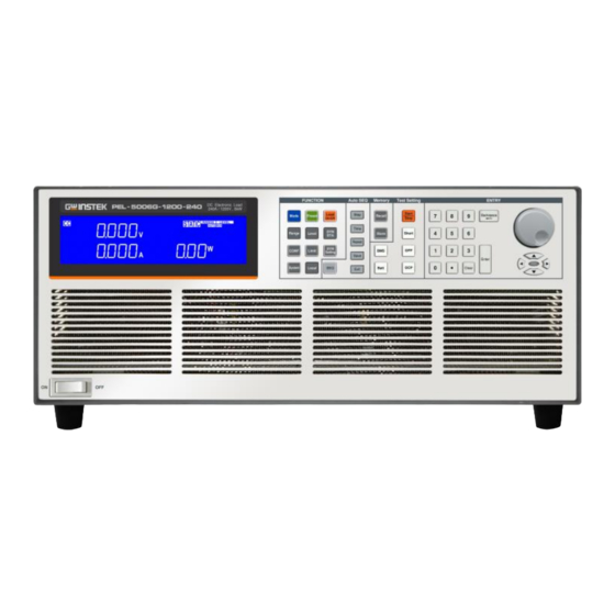
PEL-5000G Series User Manual Appearance Front Panel Power switch LCD Multi-function display Function keys Auto sequence keys Memory keys Test function keys Number keypad Knob setting... -
Page 29: Lcd Display
GETTING STARTED LCD Display The model number along with maximum 1 Model number voltage, current and power values are detailed and sink ranges in this position at the top of the load front panel. The 5 digit LCD display is a multi-function 2 Left 5 digit LCD display. - Page 30 REMOTE LCD will not be illuminated. It is LAN interface inside. 5 LAN mode Lit The PEL-5000G series Load Module features 2 7 Rang LED setting ranges for CC, CR, CV & CP operation. Indicator This allows improved resolution for setting low values.
- Page 31 CONFIG menu and turn the NG Indicator ON. If a voltmeter, ammeter or wattmeter measurement is outside these set limits then the NG indicator will illuminate. If PEL-5000G series is controlled by GPIB 10 GPIB mode through PC, the GPIB will be lit. indicator...
- Page 32 PEL-5000G Series User Manual The right 5 digit displays also changes function 13 The right 5 digit depending if the unit is in normal mode or one displays of the setting menus has been activated. Setting display: Display system setting state or auto sequence setting value.
- Page 33 GETTING STARTED value in watts “W”. NG displays whether the NG flag is set to “ON” or “OFF”. Each press of the DYN setting button changes DYN Setting the text on the middle LCD. The sequence and the corresponding setting value shown on the bottom display are as follows: T-Hi (time high) displays the set value in ...
- Page 34 PEL-5000G Series User Manual CV_bW This allows the parameters of the short test SHORT test to be set up. Each press of the SHORT button moves the setting function. The sequence of the short test along with the setting value is...
- Page 35 GETTING STARTED If the Device under Test is able to supply the load according to the values set then the middle display will show PASS and the right display will show the maximum power taken during the OPP test. If, during the test, OTP is displayed the over temperature Protection has been engaged.
- Page 36 PEL-5000G Series User Manual In normal mode the right 5 digit displays Normal mode shows the power consumption in Watts (W). The right display together with the rotary Setting mode adjustment knob is used to set values. The value changes according to the setting function that is active.
- Page 37 There are four operating modes. These can be 15 Mode and CC, selected in turn by pressing the “MODE” key CR, CV, CP on the PEL-5000G series electronic load indicators module. The sequence is: (CC) Constant Current (CR) Constant Resistance ...
-
Page 38: Function Description
PEL-5000G Series User Manual UNCTION DESCRIPTION Function keys description ........... 37 Test keys description ........... 54 System and Memory keys description ......76 Auto Sequence keys description ........81 Test keys description ........... 85... -
Page 39: Function Keys Description
FUNCTION DESCRIPTION Function keys description The function keys on the front panel of PEL-5000G series mainframe are designed for high testing throughput purpose. There are 150 operation states or testing steps can be store in the EEPROM memory of PEL-5000G series electronic load respectively, each state can store or recall the load status and level for electronic load simultaneously. - Page 40 PEL-5000G Series User Manual according to the preset values) LOAD button unlit = LOAD OFF (the load does not sink current) Turning the LOAD OFF does not affect the preset values. When the LOAD ON state is enabled the unit will revert to sinking according to the preset values.
- Page 41 DYN key and is in the ON state. Press it DYNAMIC indicators again to switch to the Static mode. At this time, the LCD display is in the STATIC ON state, and the PEL-5000G series electronic load is automatically adjusted...
- Page 42 PEL-5000G Series User Manual to the static mode.
- Page 43 FUNCTION DESCRIPTION 1. In the Static mode, the Low level gear changes with Note the High level gear. 2. The Rise/ Fall gear also changes with the high level gear. 3. Only Low/ High level changes are provided in CP mode.
- Page 44 PEL-5000G Series User Manual The setting sequence is shown below: AddCV (CC + CURRENT LIMIT or CP+CV upper limit) V_Hi (DVM upper limit) V_Lo (DVM lower limit) I_Hi (DAM upper limit) I_Lo (DAM lower limit) ...
- Page 45 FUNCTION DESCRIPTION Setting CC + CURRENT LIMIT or CP+CV upper limit voltage, middle 5 digit LCD display ”AddCV”, right 5 digit LCD display the unit is “V” ,The AddCV set range from 0.00V to 150.000V step 0.0025V by rotating the setting knob.
- Page 46 PEL-5000G Series User Manual Setting lower limit current IL , middle 5 digit LCD display “I-Lo “, right 5 digit LCD display the unit is “A”, the I-Lo set range from 0.000A to 600.00A step 9.6mA by rotating the setting knob.
- Page 47 FUNCTION DESCRIPTION Current Load Current Voltage High CC Dynamic mode, press Limit key to set the Level Hi and Level Low voltage upper Limit and lower limits of the GO/ NG. Current Level High Level Voltage High CR mode, press Limit key to set the V-Hi and V-Lo voltage upper and lower limits Limit of the GO/ NG.
- Page 48 PEL-5000G Series User Manual High Load Load input Current Load Input Voltage Voltage CP mode, press Limit key to set the W-Hi and W-Lo power upper and lower limits Limit of the GO / NG. The DYN button allows the user to define...
- Page 49 FUNCTION DESCRIPTION RISE (rise time) FALL (fall time ) SUR. I NOR. I DYN setting function OFF The time that the waveform is high includes the rise time and is set in “ms”. The time that the waveform is low includes the fall time and is set in “ms”.
- Page 50 PEL-5000G Series User Manual Press DYN Setting key, LED will ON and setting level high period, middle 5 digit LCD display will show ”T-Hi”, right 5 digit LCD display will show setting value, the unit is “ms” , The T-Hi set range from 0.010 ms to 9999 ms step...
- Page 51 FUNCTION DESCRIPTION Setting fall time, middle 5 digit LCD display will show “FALL”, right 5 digit LCD display will show setting value, the unit is “A/μs”, the FALL time set range from 0.3840A/μs to 24.000A/μs step 0.096A/μs by rotating the setting knob.
- Page 52 PEL-5000G Series User Manual Setting S.STEP, middle 5 digit LCD display will show “S.STEP”, right 5 digit LCD display will show setting value, the S.STEP set range from 1 to 5 step 1 by rotating the setting knob, Press the Start button to start the test.
- Page 53 FUNCTION DESCRIPTION (Voltage at which LOAD turns ON) LDoff (Voltage at which LOAD turns OFF) POLAR (change polarity symbol) TURBO EXTIN CV_bW Exit CONFIG options The adjustable LDon (LOAD ON) voltage is valid for Note CC, CR &...
- Page 54 PEL-5000G Series User Manual Set vsense and load input switching methods, the middle of the 5 digit LCD display will show “SENSE”, right 5 digit LCD display will show “AUTO” or “ON”. Set Load ON voltage, the middle of the ...
- Page 55 FUNCTION DESCRIPTION Set AVG, the middle of the 5 digit LCD display will show “AVG”, the right 5 digits LCD display “1”, the AVG setting range from 1 to 64 steps 1 by rotating the setting knob. Setting TURBO middle of the 5 digit ...
-
Page 56: Test Keys Description
The Setting key allows the parameters of a SHORT circuit test to be entered. The SHORT test will attempt to sink high current up to the PEL-5000G series load maximum current in order to check the power source’s protection and behavior. - Page 57 FUNCTION DESCRIPTION SHORT Time (CONTI = Continuous or 100ms to 10,000ms possible) SHORT V_Hi (High voltage threshold setting) SHORT V_Lo (Low voltage threshold setting Exit SHORT test set-up Set the short test time, the LCD display ...
- Page 58 PEL-5000G Series User Manual...
- Page 59 FUNCTION DESCRIPTION V-Hi : Short test voltage check upper limitation setting, the LCD display shows “SHORT” on left 5 digit LCD display, middle 5 digit LCD display ”V- Hi”, right 5 digit LCD display setting value, the unit is “V”. The V-Hi setting range from 0.00V to 600.00V and each step is 0.0025V by rotating the setting knob.
- Page 60 PEL-5000G Series User Manual If continuous short time is selected the test is ended by pressing the Start/Stop button. The OCP key allows the parameters of an over current protection test to be entered. parameters setting The OCP test will ramp up the load current in steps to validate the device under test’s (DUT) protection and...
- Page 61 FUNCTION DESCRIPTION OCP Vth (the voltage threshold setting) Exit OCP test set-up ISTAR: Set the start current point, the LCD display shows “OCP” on left 5 digit LCD display, middle 5 digit LCD display “ISTAR”, right 5 digit LCD display setting value, the unit is “A”.
- Page 62 PEL-5000G Series User Manual ISTOP: Set the stop current point, the LCD display shows “OCP” on left 5 digit LCD display, middle 5 digit LCD display “ISTOP”, right 5 digit LCD display setting value, the unit is “A”, the setting range is 0.000A to the full scale of the CC mode specification.
- Page 63 FUNCTION DESCRIPTION The message PASS will be displayed if the DUTs voltage stays above the set threshold. Also to PASS the OCP test the current taken from the DUT cannot equal the I STOP setting. If the DUT passes the OCP test the maximum current taken during the test is displayed on the right LCD.
- Page 64 PEL-5000G Series User Manual OPP P STAR (power starting point of the OPP test) OPP P STEP (value of incremental current steps from P START) OPP P STOP (the OPP test’s upper threshold power limit) OPP Vth (the voltage threshold setting) ...
- Page 65 FUNCTION DESCRIPTION PSTEP: Set the increment step power, the LCD display shows “OPP” on left 5 digit LCD display, middle 5 digit LCD display “PSTEP”, right 5 digit LCD display setting value, the unit is “W”. The setting range is 0.00W to the full scale of the CP mode specification.
- Page 66 PEL-5000G Series User Manual Once the test parameters have been Start entered, the test is started by pressing the Stop red Start/Stop button while the OPP PRESS START text is displayed. During the test, the middle LCD will show run and the actual current being taken will be displayed on the right LCD.
- Page 67 FUNCTION DESCRIPTION follows: There are 5 parameters for the DISch test function, as the parameters of CC, VOLT.V, TIME.S, CAP.AH and CAP.WH. Press the Batt button again to set stop discharge voltage VOLT.V(=UVP:Under Batt Voltage Protect), set stop discharge time TIMES.S, set stop discharge capacity CAP.AH, set stop discharge capacity CAP.wH...
- Page 68 PEL-5000G Series User Manual Set the stop discharge voltage STOP “VOLT.V”, the 5 digit display in the middle displays “VOLT.V”, and the 5- digit display below displays the setting value in V. The setting range of STOP VOLT.V is from 0.00V to full scale, resolution: 0.0025V.
- Page 69 FUNCTION DESCRIPTION The sequence of Batt DISch CP setting is as follows: There are 5 parameters for the DISch test function, as the parameters of CP, VOLT.V, TIME.S, CAP.AH and CAP.WH. Press the Batt button again to set stop discharge voltage VOLT.V(=UVP: Under Batt Voltage Protect), set stop discharge time TIMES.S, set stop discharge capacity...
- Page 70 PEL-5000G Series User Manual Set the stop discharge voltage STOP “VOLT.V”, the 5 digit display in the middle displays “VOLT.V”, and the 5- digit display below displays the setting value in V. The setting range of STOP VOLT.V is from 0.00V to full scale, resolution: 0.0025V.
- Page 71 SHORT ITH To test the protection status of BMS P+, P- terminal short circuit, PEL-5000G series will measure the peak current, protection time, short circuit test sequence as shown in the figure below, setting method: Press the Short key to set the Short time (0.010~10.000ms, default 10ms), Ith (0.01~300A), then return to the...
- Page 72 PEL-5000G Series User Manual Setting the BMS Short Time, the upper 5 digit monitor display the “SHORT”, the middle 5 digit monitor display the “TIME”, and lower monitor display setting value, the unit is “ms”. The range is 0.05ms to the 10.000ms, step 0.01ms by rotating the setting knob.
- Page 73 FUNCTION DESCRIPTION All models of Model SHORT ITH SHORT ITH PEL-5004G-150-400 200A PEL-5005G-150-500 250A PEL-5006G-150-600 300A PEL-5004G-600-280 140A PEL-5005G-600-350 175A PEL-5006G-600-420 210A PEL-5004G-1200-160 PEL-5005G-1200-200 100A PEL-5006G-1200-240 120A BMS OCP test setting parameters, the BMS OCP Test Setting Sequence is shown below: Short OCP PRESS START ...
- Page 74 PEL-5000G Series User Manual To test the protection state of overcharge or over discharge of BMS, PEL-5000G series will measure the current of overcharge or over discharge, protection time, OCCP/OCDP (Over Current Charge/ Discharge Protection) are all tested by OCP, and the difference is in POWER &...
- Page 75 FUNCTION DESCRIPTION Setting the BMS OCP ISTAR current, the upper 5 digit monitor display the “OCP”, the middle 5 digit monitor display the “ISTAR”, and lower monitor display setting value, the unit is “A”. The range is 0.96A to the 600.00A, step 9.6mA by rotating the setting knob.
- Page 76 PEL-5000G Series User Manual Setting the BMS OCP TSTEP, the upper 5 digit monitor display the “OCP”, the middle 5 digit monitor display the “TSTEP”, and lower monitor display setting value, the unit is “ms”. The range is 0.05ms to the 1000ms, step 0.01ms by rotating the setting knob.
- Page 77 FUNCTION DESCRIPTION...
-
Page 78: System And Memory Keys Description
PEL-5000G Series User Manual System and Memory keys description Press SYSTEM to set the argument, GPIB System key address, RS232 BAUD- RATE, WAKE UP System buzzer Alarm power ON/OFF and Master/Slave parallel control. Press Local key to exit remote mode... - Page 79 5 digit LCD display setting BAUD- RATE, press up, down buttons to adjust the value of BAUD RATE, then press ENTER, PEL-5000G series is saved setting BAUD RATE, press System key three times to leave the BAUD-RATE setting state.
- Page 80 System the PEL-5000G series every time. Press the System key three times, the LCD display shows WAKE on left 5 digit LCD display, middle 5 digit LCD display UP, right 5 digit LCD display setting, press up, down buttons to adjust the 0~150.
- Page 81 Note use the KEYPAD ENTER button to confirm, otherwise PEL-5000G series will not save the changes the settings. Pass: Automatic test mode, no NG state, is the PASS. Fail: Automatic test mode, any test if the NG then is the FAIL.
- Page 82 PEL-5000G Series User Manual Press Recall key to enter the call state. RECALL operation Press up, down keys or keypad to Recall adjust. Finally, press the Enter key to confirm. In the front panel of electronic load, set...
-
Page 83: Auto Sequence Keys Description
FUNCTION DESCRIPTION Auto Sequence keys description PEL-5000G series has AUTO SEQUENCE AUTO function, PEL-5000G series to select the SEQUENCE instructions state F1~F9 Automatic testing can be edited, 16 steps each group can be set to select 150 group of the STATE, within each step can be set TEST TIME Units of 100 ms range (0.1s ~ 9.9s). - Page 84 PEL-5000G Series User Manual Press ENTER to set TIME value, press Test time up, down keys or KEYPAD to adjust setting settings, range from 100 ms~9999ms. Press Enter key or SAVE key to finish editing, if you do not save the settings, press the Exit key to leave edit mode.
- Page 85 FUNCTION DESCRIPTION Press the SEQ key to enter the AUTO Test mode SEQUENCE mode. Press up, down keys to select TEST, the LCD display shows TEST on left 5 digit LCD display, middle 5 digit LCD display FX, “FX” means to select the state F1-F9, Press keypad key 1 ~ 9 choose F1 ~ F9.
- Page 86 PEL-5000G Series User Manual Press “Shift”+ “SEQ.” key SEQ. Mode Press “Shift”+ “Exit” key ▲ Press key to select Mode Edit Mode Test Mode Keypad 1~9 select F1~F9 Press “Enter” key Start Test Recall 1~150 Testing Press “Shift”+ “Exit” key...
-
Page 87: Entry Description
FUNCTION DESCRIPTION Entry description The rotary knob and arrow keys are used to increase Rotary Knob or decrease the set values. and arrow Keys Clockwise the rotary switch and up arrow key to increase the setting values. Anti-clockwise and down arrow key operation of the rotary knob ... - Page 88 PEL-5000G Series User Manual Clear key: Press the Clear key to clear the input value. In CR mode, the up arrow key and clockwise operation of Note the rotary knob reduces the resistance. In CR mode, the down arrow key and anti-clockwise...
-
Page 89: Connection
CONNECTION ONNECTION Rear Panel ..............88 Connecting the I-monitor to an oscilloscope....92 Master/Slave Instructions ........... 93... -
Page 90: Rear Panel
Please ensure that the voltage and current rating of the DUT do not exceed the maximum rating of the PEL-5000G series load module being used. Please also check the output polarity of the DUT prior to connection and testing. - Page 91 REFER SERVICING TO QUALIFIED PERSONNEL. MAX. LOAD 150V MAX. Typical connection of PEL-5000G series load module If V-sense is set to AUTO and the sense leads are Note connected to the DUT the losses need to be approx. before the display compensates for the voltage loss.
- Page 92 PEL-5000G Series User Manual is also 150Vdc. The I-monitor is provided as a Terminal. It is 3 I-monitor designed to enable the user to monitor the terminal electronic load’s input current or short current. The I-monitor’s signal is 0V to 10V. This signal is proportional to the full scale current that the particular electronic load is capable of.
- Page 93 The analog programming input is configured as a Terminal on the mainframe’s rear panel. The analogue programming input operates in CC or CP modes only. The PEL-5000G series Load will attempt to load proportionally according to the signal and the load module’s maximum current or power range.
-
Page 94: Connecting The I-Monitor To An Oscilloscope
PEL-5000G Series User Manual Connecting the I-monitor to an oscilloscope When you connect this product to an oscilloscope, please ensure the correct polarities of the connecting probes as shown in fig below AEL-5000 Series (Correct) Oscilloscope Connections to Load Load... -
Page 95: Master/Slave Instructions
CONNECTION Master/Slave Instructions PEL-5000G series “MASTER / SLAVE” parallel function. 1 master and 7 slaves can be connected. Setting mothod 1. Press the System key to set the CONTROL MODE to select ALONE, MASTER or SLAVE1 ~ 7. 2. Press the Enter key to set. When Power off data will not be lost and this parameter is saved. - Page 96 PEL-5000G Series User Manual The following procedure should be followed before applying power off. Master/Slave mains: Step1. Turn off (I) the Master POWER switch. Step2. Turn off (I) the Slave POWER switch. Parallel method Use HD-DSUB 15pin 1: 1 Cable to connect the...
- Page 97 CONNECTION CP: 1000W = Master 500W + Slave 500W. CC Set 30A Master Display Slave Display CR Set 7500.0Ω Master Display Slave Display CV Set 100V Master Display Slave Display CP Set 1000W Master Display Slave Display Master Mode operation except CC / CR / CV / CP Note Mode, The following functions will be disabled.
- Page 98 PEL-5000G Series User Manual Rrmote operating Master Mode can use the command as follows Setting preset numeric command Remark MODE{SP}{CC│CR│CV│CP}{;|NL} RISE{SP}{NR2}{;|NL} A/us FALL{SP}{NR2}{;|NL} A/us PERD:{HIGH|LOW}{SP}NR2}{;|NL} LDONV{SP}{NR2}{;|NL} LDOFFV{SP}{NR2}{;|NL} CC|CURR:{HIGH|LOW}{SP}{NR2}{;|NL} CP:{HIGH|LOW}{SP}{NR2}{;|NL} CR|RES:{HIGH|LOW}{SP}{NR2}{;|NL} CV|VOLT:{HIGH|LOW}{SP}{NR2}{;|NL} SENS{SP}{ON|OFF|AUTO|1|0}{;|NL} 0: OFF/AUTO, 1: ON LEV{SP}{LOW|HIGH|0|1}{;|NL} DYN{SP}{ON|OFF|1|0}{;|NL} LOAD{SP}{ON|OFF|1|0}{;|NL} MEAS:CURR?{;|NL} MEAS:VOLT?{;|NL}...
-
Page 99: Installation
INSTALLATION NSTALLATION The PEL-5000G series high power load was carefully inspected before shipment. If instrument damage has occurred during transport, please inform GW Instek's sales and service office or representative. Your PEL-5000G series high power load was shipped with a power cord for the type of Terminal blocks used at your location. -
Page 100: Check Line Voltage
Skip this procedure if the label is corrected marked. Installation 1. With the PEL-5000G series load power OFF, disconnect the power cord. 2. Refer the drawing on the rear panel of PEL- 5000G series high power load as figure below. -
Page 101: Power Up
INSTALLATION Power up The following procedure should be followed before applying mains power. Procedure 1. Turn off (O) the POWER switch. 2. Check that the power cord is corrected. 3. Check that nothing is connected to the DC INPUT on the rear panels. 4. -
Page 102: Interface Option
GPIB & RS232 Interface Procedure 1. GPIB + RS232 interface is on the rear panel of PEL-5000G series mainframe for application GPIB or RS232. 2. GPIB and RS232 interface can only be used at the same time, to change the interface must reboot unit. -
Page 103: Rs232 Interface
INSTALLATION PEL-5000G Series GPIB & RS232 interface RS232 interface The figure below shows the RS232 connector (Female) on the rear panel connects PEL-5000G series mainframe to RS232 port of computer in one by one configuration .The RS232 BAUD-RATE can be set in the front panel, it will be lit the GPIB address when press the “System”... -
Page 104: Usb Interface
PEL-5000G Series GPIB interface USB interface The figure below shows the USB connector in the rear panel of PEL-5000G series mainframe. Please refer to appendix “PEL-5000G series USB Instruction” on page 245. PEL-5000G USB interface LAN interface The figure below shows the LAN connector in the rear panel of PEL-5000G series mainframe. - Page 105 INSTALLATION PEL-5000G LAN interface 9923 interface (optional) The figure below shows the 9923 connector in the rear panel of 3350G series mainframe. Please refer to page 204. PEL-5000G series 9923 interface...
-
Page 106: I/O Connection
PEL-5000G Series User Manual I/O connection PEL-5000G series I/O Interface with Vsense, Analog Programming Input, Imonitor. For instructions about I/O, please refer to page 88. PEL-5000G series SENSE I/O interface 0 10Vdc F.S.10V ANALOG MONITOR INPUT 150V MAX. -
Page 107: Load Current Slew Rate Setting
The slew rate determines a rate at which the current changes to a new programmed value. The slew rate can be set at the front panel or via GPIB on the rear panel of PEL-5000G series high power load. The rise and fall slew rate can be independently... - Page 108 PEL-5000G Series User Manual Load ON/OFF switch. So, you could do all items of Power Supply testing task by using constant current mode only, it can significantly improve the testing quality and process as well as efficiency. There are two load current range in PEL-5000G...
-
Page 109: Load Wire Inductance
This voltage applies to all of the load input terminals of the PEL-5000G series when the impedance of the EUT is relatively small. The voltage generated by the load wire inductance (L) and the current variation (I) is expressed using the following equation. - Page 110 PEL-5000G Series User Manual In general, the wire inductance can be measured approximately 1 μH per 1 meter. If the 10 meters of Load wires is connected between the EUT and the electronic load (PEL- 5000G Series) with the current variation of 2 A/μs, the voltage generated by the wire...
- Page 111 INSTALLATION Current ΔI ΔT Voltage at load input terminal When the voltage drops under minimum operating Minimum operating voltage voltage, the electronic load may generate unstable oscillation. Waveform example: Generate unstable oscillation CH1= Imonitor CH2=Power Supply output Voltage (x10) CH3= LOAD Input Voltage (x10)
- Page 112 In the case of DC operation also, the phase delay of the current may cause instability in the PEL-5000G series control inducing oscillation. In this case also, connect the PEL-5000G series and the equipment under test using the shortest twisted wire possible.
-
Page 113: Remote Control
When use USB/LAN interface controls the PEL-5000G Note series, the PEL-5000G series will convert the USB/LAN interface to RS232 interface. Configure RS232C ............. 112 Communication Interface programming command list ............ -
Page 114: Configure Rs232C
PEL-5000G Series User Manual Configure RS232C The following RS232 commands are same as GPIB commands. The RS232 protocol in PEL-5000G Series mainframe is listing below: RS232C Baud Rate 9600~115200bps Configuration Stop Bit 1 bit Data Bit 8 bits Parity None... - Page 115 REMOTE CONTROL Abbreviation Description Pin1 Carrier Detect Pin2 Receive Pin3 Transmit Pin4 Data Terminal Ready Pin5 Ground Pin6 Data Set Ready Pin7 Request To Send Pin8 Clear To Send Pin9 Ring Indicator...
-
Page 116: Communication Interface Programming Command List
PEL-5000G Series User Manual Communication Interface programming command list SIMPLE TYPE FORMAT Communication interface programming setting command summary Setting preset numeric command Remark RISE{SP}{NR2}{|NL} A/us FALL{SP}{;|NL} A/us PERD:{HIGH|LOW}{SP}{NR2}{;|NL} LDONV{SP}{NR2}{;|NL} LDOFFV{SP}{NR2}{;|NL} CC|CURR:{HIGH|LOW}{SP}{NR2}{;|NL} CP:{HIGH|LOW}{SP}{NR2}{;|NL} CR|RES:{HIGH|LOW}{SP}{NR2}{;|NL} CV|VOLT:{HIGH|LOW}{SP}{NR2}{;|NL} TCONFIG{SP}{NORMAL|OCP|OPP |SHORT} {;|NL} Set OCP start current (Istart), OCP:START{SP}{NR2}{;|NL}... - Page 117 REMOTE CONTROL SURGE:NORI{NR2}{;|NL} SURGE:TIME{NR2}{;|NL} Surge time:10~1000ms SURGE:STEP{SP}{n}{;|NL} n=1~5 SURGE{ON|OFF}{;|NL} ON: Run surge, OFF: Stop BMS{SP}{ON|OFF|1|0}{;|NL} Enable/disable BMS test function ON: Enable, OFF: Disable BMS:STIME{SP}{NR2}{;|NL} Set BMS short time, Unit: ms, 0.05~10ms SHORT:ITH{SP}{NR2}{;|NL} Set BMS short ITH, Unit: A OCP:ITH{SP}{NR2}{;|NL} Set BMS OCP ITH, Unit: A OCP:TSTEP{SP}{NR2}{;|NL} Set BMS OCP Tstep, Unit: ms, 0.05 ~ 10ms/ 11~1000ms...
- Page 118 PEL-5000G Series User Manual OCP:STEP{?}{;|NL} ###.#### OCP:STOP{?}{;|NL} ###.#### VTH{?}{;|NL} ###.#### OPP:START{?}{;|NL} ###.#### OPP:STEP{?}{;|NL} ###.#### OPP:STOP{?}{;|NL} ###.#### STIME{?}{;|NL} ###.#### OCP{?}{;|NL} ###.#### OPP{?}{;|NL} ###.#### BATT:RAH{?}{;|NL} Read BATT test result AH BATT:RWH{?}{;|NL} Read BATT test result WH BATT:RTIME{?}{;|NL} Read BATT test result TIME BATT:RVOLT{?}{;|NL}...
- Page 119 REMOTE CONTROL LIM:ADDCV:POW{?}{;|NL} ###.#### LIM:ADDCV:{SP}{ON|OFF}{;|NL}...
- Page 120 PEL-5000G Series User Manual State command summary State command Remark LOAD{SP}{ON|OFF|1|0}{;|NL} LOAD{?}{;|NL} 0: OFF, 1: ON MODE{SP}{CC|CR|CV|CP}{;|NL} MODE{?}{;|NL} 0: CC, 1: CR, 2: CV, 3: CP SHOR{SP}{ON|OFF|1|0}{;|NL} SHOR{?}{;|NL} 0: OFF, 1: ON PRES{SP}{ON|OFF|1|0}{;|NL} PRES{?}{;|NL} 0: OFF, 1: ON SENSe{SP}{ON|OFF|AUTO|1|0}{;|NL} SENSe{?}{;|NL} 0: OFF/AUTO, 1:ON LEV{SP}{LOW|HIGH|0|1}{;|NL}...
-
Page 121: System Command
REMOTE CONTROL System command System command summary Command Note Return RECALL{SP}{m}{;|NL} m=1~150, m: STATE STORE{SP}{m}{;|NL} m=1~150 m: STATE REMOTE{;|NL} RS232/USB/LAN command LOCAL{;|NL} RS232/USB/LAN command NAME{?}{;|NL} “XXXXX” *RST{;|NL} Measure command Measure command summary Command Return MEAS:CURR{?}{;|NL} ###.#### MEAS:VOLT{?}{;|NL} ###.#### MEAS:POW{?}{;|NL} ###.#### MEAS:VC{?}{;|NL} ###.####,###.#### Remark... -
Page 122: Auto Sequence Command
PEL-5000G Series User Manual Auto sequence command Auto sequence command list Auto sequence setting command Note Return FILE{SP}{n}{;|NL} n = 1~9 1 ~ 9 FILE{?}{;|NL} n = 1~9 1 ~ 9 STEP{SP}{n}{;|NL} n = 1~16 1 ~ 16 STEP{?}{;|NL} n = 1~16 1 ~ 16 TOTSTEP{SP}{n}{;|NL}... -
Page 123: Complex Type Format
REMOTE CONTROL COMPLEX TYPE FORMAT Communication interface programming setting command summary Setting command summary Remark PRESet:RISE{SP}{NR2}{;|NL} A/us PRESet:FALL{SP}{;|NL} A/us PRESet:PERD:{HIGH|LOW}{SP}{NR2}{;|NL} PRESet:LDONv{SP}{NR2}{;|NL} PRESet:LDOFfv{SP}{NR2}{;|NL} PRESet:CC|CURR:{HIGH|LOW}{SP}{NR2}{;|NL} PRESet:CP:{HIGH|LOW}{SP}{NR2}{;|NL} PRESet:CR|RES:{HIGH|LOW}{SP}{NR2}{;|NL} PRESet:CV|VOLT:{HIGH|LOW}{SP}{NR2} {;|NL} PRESet:TCONFIG{SP}{NORMAL|OCP|OPP| SHORT}{;|NL} Set OCP start current [PRESet:]OCP:START{SP}{NR2}{;|NL} (Istart), unit: A Set OCP step current [PRESet:]OCP:STEP{SP}{NR2}{;|NL} (Istep), unit: A Set OCP stop current... - Page 124 PEL-5000G Series User Manual PRESet:SURGE:STEP{SP}{n}{;|NL} n=1~5 ON: Run surge, PRESet:SURGE{ON|OFF}{;|NL} OFF: Stop Enable/disable BMS test function PRESet:BMS{SP}{ON|OFF|1|0}{;|NL} ON: enable, OFF: Disable Set BMS short time, PRESet:BMS:STIME{SP}{NR2}{;|NL} Unit: ms, 0.05~10ms Set BMS short ITH, PRESet:SHORT:ITH{SP}{NR2}{;|NL} Unit: A Set BMS OCP ITH, PRESet:OCP:ITH{SP}{NR2}{;|NL}...
- Page 125 REMOTE CONTROL PRESet:CR|RES:{HIGH|LOW}{?}{;|NL} ###.#### PRESet:CV|VOLT:{HIGH|LOW}{?}{;|NL} ###.#### 1: NORMAL, 2: OCP [PRESet:]TCONFIG{?}{;|NL} 3: OPP, 4: SHORT [PRESet:]OCP:START{?}{;|NL} ###.#### [PRESet:]OCP:STEP{?}{;|NL} ###.#### [PRESet:]OCP:STOP{?}{;|NL} ###.#### [PRESet:]VTH{?}{;|NL} ###.#### [PRESet:]OPP:START{?}{;|NL} ###.#### [PRESet:]OPP:STEP{?}{;|NL} ###.#### [PRESet:]OPP:STOP{?}{;|NL} ###.#### [PRESet:]STIME{?}{;|NL} ###.#### PRESet:OCP{?} ###.#### PRESet:OPP{?} ###.#### PRESet:BATT:RAH{?}{;|NL} Read BATT test result AH PRESet:BATT:RWH{?}{;|NL} Read BATT test result WH PRESet:BATT:RTIME{?}{;|NL}...
- Page 126 PEL-5000G Series User Manual [LIMit:]ADDCV:VOLTage{SP}{NR2}{;|NL} [LIMit:]ADDCV:VOLTage{?}{;|NL} ###.#### [LIMit:]ADDCV:CURR{SP}{NR2}{;|NL} [LIMit:] ADDCV:CURR{?}{;|NL} ###.#### [LIMit:]ADDCV:POW{SP}{NR2}{;|NL} [LIMit:]ADDCV:POW{?}{;|NL} ###.#### [LIMit:] ADDCV:{SP}{ON|OFF}{;|NL} State command summary State command Remark [STATe:]LOAD{SP}{ON|OFF}{;|NL} [STATe:]LOAD{?}{;|NL} 0: OFF, 1: ON [STATe:]MODE{SP}{CC|CR|CV|CP}{;NL} [STATe:]MODE{?}{;|NL} 0: CC, 1: CR, 2: CV, 3: CP [STATe:]SHOR{SP}{ON|OFF}{;|NL} [STATe:]SHOR{?}{;|NL} 0: OFF, 1: ON [STATe:]PRES{SP}{ON|OFF}{;|NL}...
- Page 127 REMOTE CONTROL System command summary Command Note Return [SYStem:]RECall{SP}{m}{;|NL} m=1~150, m: State [SYStem:]STORe{SP}{m}{;|NL} m=1~150, m: State [SYStem:]REMOTE{;|NL} RS232/USB/LAN command [SYStem:]LOCAL{;|NL} RS232/USB/LAN command [SYStem:]NAME?{;|NL} “XXXXX” [SYStem:]*RST{;|NL} Measure command summary Command Return MEASure:CURRent{?}{;|NL} ###.#### MEASure:VOLTage{?}{;|NL} ###.#### MEASure:POWer{?}{;|NL} ###.#### MEASure:VC{?}{;|NL} ###.####,###.#### Remark 1. Current engineering unit: A 2.
- Page 128 PEL-5000G Series User Manual SAVE{;|NL} Save “File n” data REPEAT{SP}{n}{;|NL} n = 0 ~ 9999 0 ~ 9999 REPEAT{?}{;|NL} n = 0 ~ 9999 0 ~ 9999 Auto reply “PASS” or RUN{SP}{F}{n}{;|NL} n=1~9 “FAIL: XX” (XX=NG STEP)
-
Page 129: Command Syntax
REMOTE CONTROL Command Syntax The description of abbreviation SP: Space, the ASCII code is 20 Hexadecimal. Command Tree ;:Semicolon, Program line terminator, the ASCII code is OA Hexadecimal. NL:New line, Program line terminator, the ASCII code is OA Hexadecimal. NR2:Digits with decimal point. It can be accepted in the range and format of ###.#####. - Page 130 PEL-5000G Series User Manual This symbol means option. For example “LOW|HIGH”means it can only use LOW or HIGH as the command, it can choose only one as the setting command. Terminator: You have to send the program line terminator character after send the GPIB...
-
Page 131: Command List
REMOTE CONTROL Command List Preset Commands ........... 132 RISE ..................... 132 FALL ....................132 PERI or PERD................... 133 LDONv ....................133 LDOFfv ....................134 CURR:HIGH|LOW ................. 134 CP:{HIGH|LOW} ................135 CR|RES:{HIGH|LOW} ..............135 CV:{HIGH|LOW} ................135 TCONFIG ..................136 OCP:START ..................137 OCP:STEP .................. - Page 132 PEL-5000G Series User Manual BMS:STIME ..................143 SHORT:ITH ..................143 OCP:ITH .................... 144 OCP:TSTEP ..................144 AVG ....................144 TURBO{ON|OFF} ................ 144 EXT:AIN{ON|OFF} ..............145 SEQLD:TOTSTEP ................145 SEQLD:TIME ................... 145 SEQLD:CC ..................146 SEQLD:CP ..................146 Limit Commands ............. 147 [LIMit:]CURRent:{HIGH|LOW} or IH|IL ......
- Page 133 REMOTE CONTROL [SYStem:]NAME? ................156 [SYStem:]REMOTE ................157 [SYStem:]LOCAL ................157 Measure Commands ................158 MEASure:CURRent? ................. 158 MEASure:VOLTage? ................ 158 MEASure:POWer?................158 Auto Sequence Commands ........159 FILE ..................... 159 STEP ....................159 TOTSTEP ................... 159 SB ......................159 TIME ....................
-
Page 134: Preset Commands
The least significant number is the 3th behind the decimal point. PEL-5000G series will set to the maximum value of the model automatically when the set RISE is over the specification of Load. -
Page 135: Peri Or Perd
The least significant number is the 5th behind the decimal point. PEL-5000G series will set the value of TLOW or THIGH automatically when the value which has been set is over the maximum of the Load. -
Page 136: Ldoffv
The least significant number is the 5th behind the decimal point. PEL-5000G series will set the maximum value of current of the load automatically when the value which has been set is over the maximum of the load. -
Page 137: Cp:{High|Low
The least significant number is the 3rd behind the decimal point. PEL-5000G series will set to the maximum value of the model automatically when the value of Resistance which has been set is over the specification of load. -
Page 138: Tconfig
The least significant number is the 5th behind the decimal point. PEL-5000G series will set to the maximum value of the model automatically when the value of voltage which has been set is over the specification of load. -
Page 139: Ocp:start
REMOTE CONTROL OCP:START Query Set and read the initial value of OCP test. This Description command is used for setting the required initial value (I-START) of OCP test. Syntax [PRESet:]OCP:START{SP}{NR2}{;|NL} Query Syntax [PRESet:]OCP:START?{;|NL} OCP:STEP Query Set and read the increasing value of OCP test. This Description command is used for setting the increasing value (I-STEP) of OCP test. -
Page 140: Vth
PEL-5000G Series User Manual Query Set and read the value of the threshold voltage. Description This command is used for setting the threshold voltage. That is the OCP/OPP of this load model when the output voltage of appliance is lower or... -
Page 141: Opp
REMOTE CONTROL Syntax [PRESet:]OPP:STOP{SP}{NR2}{;|NL} Query Syntax [PRESet:]OPP:STOP?{;|NL} Query Read OPP testing watt. This command is used for Description reading OPP watt. Query Syntax OPP? STIME Query Set and read time of the short-circuit test. This Description command is used for setting time of the short- circuit test. -
Page 142: Batt:ah
PEL-5000G Series User Manual BATT:AH Query Set and read BATT Stop AH. This command is Description used to set and read BATT Stop AH. Syntax [PRESet:]BATT:AH{SP}{NR2}{;|NL} Query Syntax [PRESet:]BATT:AH?{;|NL} BATT:WH Query Set and read BATT STOP WH. This command is to Description set and read BATT STOP WH. -
Page 143: Batt:rwh
REMOTE CONTROL Query Syntax [PRESet:]BATT:RAH?{;|NL} BATT:RWH Query Read BATT RWH. This command is used to read Description the battery result WH. Query Syntax [PRESet:]BATT:RWH?{;|NL} BATT:RVOLT Query Read BATT RVOLT. This command is used to read Description the battery result VOLT. Query Syntax [PRESet:]BATT:RVOLT?{;|NL} BATT:CC... -
Page 144: Surge:suri
PEL-5000G Series User Manual SURGE:SURI Query Set and read surge current mode loading current Description value. This command is used to set and read surge current mode testing loading value XXX.XXX (A) SURGE CURRENT. Syntax [PRESet:]SURGE:SURI{SP}{NR2}{;|NL} Query Syntax [PRESet:]SURGE:SURI?{;|NL} SURGE:NORI... -
Page 145: Surge:on|Off
REMOTE CONTROL Syntax [PRESet:]SURGE:STEP{SP}{NR2}{;|NL} Query Syntax [PRESet:]SURGE:STEP?{;|NL} SURGE:ON|OFF Query Set and read surge mode ON or OFF. This Description command is used to set and read surge mode ON or OFF, ON: Run surge, OFF: Stop surge. Syntax [PRESet:]SURGE:{ON|OFF}{;|NL} Query Syntax [PRESet:]SURGE:{ON|OFF}?{;|NL} BMS:ON|OFF|1|0 Set BMS ON or OFF. -
Page 146: Ocp:ith
PEL-5000G Series User Manual OCP:ITH Set BMS OCP ITH. This command is used to set Description BMS OCP ITH. Unit is A. Syntax [PRESet:]OCP:ITH{SP}{NR2}{;|NL} OCP:TSTEP Set BMS OCP TSTEP. This command is used to set Description the range of BMS OCP TSTEP 0.05~10ms / 11~1000ms. -
Page 147: Ext:ain{On|Off
REMOTE CONTROL EXT:AIN{ON|OFF} External Analog input ON of OFF. This command Description is used to set external analog input ON or OFF. Syntax [PRESet:]EXT:AIN{SP}{ON|OFF}{;|NL} SEQLD:TOTSTEP Query Set and read the total test levels of SEQ MODE, Description n=2~16 Syntax SEQLD:TOTSTEP{SP}{n}{;|NL} Query Syntax SEQLD:TOTSTEP{?}{;|NL} SEQLD:TIME... -
Page 148: Seqld:cc
PEL-5000G Series User Manual SEQLD:CC Query Set and read the test current value of each level of Description SEQ CC MODE. This command is to set and read the test current of each level of SEQ CC MODE, n = 0 ~ 15, the unit is ampere (A). -
Page 149: Limit Commands
REMOTE CONTROL Limit Commands [LIMit:]CURRent:{HIGH|LOW} or IH|IL Query This command is to set the upper/lower limit Description value of threshold current. When load sink current is lower than this lower limit value or higher than the upper limit value, NG indicating light will come on to indicate “NO GOOD”. -
Page 150: [Limit:]Svh|Svl
PEL-5000G Series User Manual come on to indicate “NO GOOD”. Syntax [LIMit]:VOLtage:{HIGH|LOW}{SP}{NR2 }{;|NL} [VH|VL]{SP}{NR2}{;|NL} Query Syntax [LIMit]:VOLtage:{HIGH|LOW}?{;|NL} [VH|VL}?{;|NL} [LIMit:]SVH|SVL Query This command is to set the upper/lower limit Description value of short current. When short current is lower than the lower limit value or higher than the upper limit value, NG indicating light will come on to indicate “NO GOOD”. -
Page 151: [Limit:]Addcv:curr
REMOTE CONTROL [LIMit:]ADDCV:CURR Query Set and read the Constant current value of CC + Description CURRENT LIMIT mode. When in CC + CURRENT LIMIT mode, the load will be loaded with a Constant current until the voltage of the object under test is equal to the set Constant voltage value, then it will switch to the Constant voltage mode. -
Page 152: State Commands
PEL-5000G Series User Manual State Commands State commands are used to set and read the status of load [STATe:]LOAD Query Set and read the status of sink current or not. This Description command is used for setting the status of sink current. -
Page 153: [State:]Preset
ON, the voltage is gotten from VSENSE, and when setting is OFF, the voltage is gotten from input connector. For PEL-5000G series, the optional are ON and AUTO. So, if setting is AUTO, it means the voltage is gotten and read from VSENSE. -
Page 154: [State:]Level Or Lev{Sp}{High|Low
Syntax [STATe:]DYNamic{SP}{ON|OFF}{;|NL} Query Syntax [STATe:]DYNamic?{;|NL} [STATe:]CLR Clear the error flag of PEL-5000G series during the Description period of working. This command is for clearing the contents in the register of PROT and ERR. After implementation, the contents of these two registers will be “0”. -
Page 155: [State:]Ng
REMOTE CONTROL [STATe:]NG? Query Query if there is NG flag in this PEL-5000G series. Description The command “NG?” is used to show the NG status. When “0” is set, the LCD of NG (NO GOOD) will be put out. When ”1” is set, the LCD will be lit. -
Page 156: [State:]Ccr{Auto|R2
PEL-5000G Series User Manual [STATe:]CCR{AUTO|R2} Set the CC mode range to be forced to switch to Description Range II. It will switch the range position automatically when setting to AUTO and set when implementing RANGE II when setting to R2 Syntax [STATe:]CCR{AUTO|R2}{;|NL}... -
Page 157: [State:]Stop
REMOTE CONTROL [STATe:]STOP Set to stop the test for load Description Syntax [STATe:]STOP{;|NL} [STATe:]TESTING? Query Query to whether the PEL-5000G series is in the Description test execution state. (0: Test end, 1: During testing) Query Syntax [STATe:]TESTING{?}{;|NL}... -
Page 158: System Commands
PEL-5000G Series User Manual System Commands System commands are sued to set and read the status of PEL-5000G series [SYStem:]RECall Recall the status of loading which has been saved Description in the memory. This command is for recalling the status of load which has been saved in the memory. -
Page 159: [System:]Remote
REMOTE CONTROL shown in following table. Query Syntax [SYStem:]NAME?{;|NL} Model PEL-5004G-150-400 PEL-5004G-600-280 PEL-5004G-1200-160 PEL-5005G-150-500 PEL-5005G-600-350 PEL-5005G-1200-200 PEL-5006G-150-600 PEL-5006G-600-420 PEL-5006G-1200-240 [SYStem:]REMOTE Use this command to enter remote status (only for Description RS232). This command is for controlling the RS232. Syntax [SYStem:]REMOTE{;|NL} [SYStem:]LOCAL Use the command to exit remote status (only for Description... -
Page 160: Measure Commands
PEL-5000G Series User Manual Measure Commands Measure the actual current and voltage value of Load MEASure:CURRent? Query Read the current which is loading from load. Read Description the five digits of current meters, and the unit is Ampere (A) Query Syntax MEASure:CURRent?{;|NL}... -
Page 161: Auto Sequence Commands
REMOTE CONTROL Auto Sequence Commands FILE Query Set file numbers of Auto Sequence. Reads the Description automatic test number setting of the AUTO Sequence function and the set automatic test number. The setting range is 1-9, and the number is the automatic test number. -
Page 162: Time
PEL-5000G Series User Manual The step execution contents are various setting states (up to 150 types) saved in the PEL-5000G series memory. The setting range is 1: Various setting states 1 – 150: Various setting states 150. Syntax SB{SP}{m,n}{;|NL} Query Syntax SB{?}{;|NL}... -
Page 163: Run
Run the sequence file number. Specify an Description automatic test number and run the automatic test against that number. Specified range: 1 to 9. When the automatic test is finished, you will receive an auto reply. Syntax RUN{SP}{F}{n}{;|NL}... -
Page 164: Application
PEL-5000G Series User Manual PPLICATION This chapter details the basic operating modes along with some common applications in which the PEL-5000G series Electronic Load is used. Local sense connections ........... 164 Remote sense connections ........165 Constant Current mode application ......166 Constant Voltage mode application ...... - Page 165 APPLICATION Typical applications..................206 Stand-alone application (no need for a computer connection) ... 211 Parallel applications ..................211 9923 Installation method ................212 SEQUENCE LOAD (remote only) ......213...
-
Page 166: Local Sense Connections
PEL-5000G Series User Manual Local sense connections Local sensing is used in applications where the Background lead lengths are relatively short, or where load regulation is not critical. When connected in local sense mode the 5 digit voltage meter of the PEL- 5000G series electronic load measures the voltage at its DC input terminals. -
Page 167: Remote Sense Connections
DUT the load will check and compensate for all voltage drops. The maximum voltage sense compensation is the same as the rating of the PEL-5000G series. Vmax of PEL-5004G-150-400, PEL-5005G-150-500, Example and PEL-5006G-150-600 is 150Vdc so maximum Vsense is also 150Vdc. -
Page 168: Constant Current Mode Application
Discharge Characteristics and the Life Cycle of cells and battery packs. In CC operation the PEL-5000G series can operate as a static load with switchable high and low current levels. It is also possible to operate the load dynamically enabling the user to adjust sink current with time. - Page 169 APPLICATION Dynamic load Load current current setting setting Load current Load current The built-in pulse generators allow the user to Dynamic mode recreate real world loads that vary with time. Major application areas include: Power supply load transient response testing ...
- Page 170 The PEL-5000G series load will track and load according to the external signal as long as it is within its dynamic capability. The input signal can be the range of 0-10V (dc+ac).
-
Page 171: Constant Voltage Mode Application
APPLICATION Constant Voltage mode application In Constant Voltage (CV) operation the load will Background attempt to sink as much current as required in order to reach the set voltage value. CV operation is useful in checking the load regulation of dc current sources. - Page 172 PEL-5000G Series User Manual Constant Voltage mode application Current Source Electronic load Input CV mode Constant voltage setting CV setting Input voltage Load current Power supply current limit setting...
-
Page 173: Constant Resistance Mode Application
This feature is found within the dynamic settings as RISE slew rate. Even in static mode the PEL-5000G Series load will regulate its current demand at “Load ON” in line with the adjusted RISE slew rate. The FALL slew rate also in the dynamic settings allows the current ramp down to be controlled at “Load OFF”. - Page 174 PEL-5000G Series User Manual Constant Resistance mode Application Current Voltage Source Source Electronic load Electronic load CR mode CR mode Input Voltage Load resistance setting output Load Current...
-
Page 175: Constant Power Mode Application
(Fig b). Operating the PEL-5000G series electronic load in CP mode is ideal for testing the characteristics of a battery. This is because as the battery voltage drops the load current will automatically increase in order to keep the CP setting. - Page 176 PEL-5000G Series User Manual Along with static operation the load can also be operated dynamically in CP mode. The dynamic functions allow the ramp, fall and plateau times to be adjusted between 2 levels of power. This capability means that “real world” loads can be more accurately simulated.
-
Page 177: Applications With Current Limiting Or Power Limiting Function Cv Mode Operation (Charging Device)
CV mode operation (charging device) Operating in the current-limiting CV mode, the Background PEL-5000G series can limit current or power when operating at a Constant voltage load. It is especially suitable for charging piles, Constant current sources and other power product testing applications. - Page 178 PEL-5000G Series User Manual voltage to 50V) LIM ADDCV ON (Start testing CV+ current limit or power limit mode) MEAS: CURR? (Read the current value of the electronic load) MEAS: VOLT? (Read the voltage value of the ...
-
Page 179: Cv + Current Limit Mode Of Operation Application
CV + Current Limit mode of operation application When operating in CV + Current Limit mode, Background PEL-5000G series at the same time as a Constant Current and Constant Voltage Load, as shown in Fig below. When operating at Constant Current (CC) load,... - Page 180 PEL-5000G Series User Manual Remote Control CV + Current Limit REMOTE (Set Remote Control) MODE CC (Setting CC mode) CC: HIGH 20 (Setting load on current 20A) LIM: ADDCV:VOLT 50 (Setting constant Voltage is 50V) LIM: ADDCV ON (start test CV + Current Limit mode)
-
Page 181: Cv + Power Limit Mode Of Operation Application
5000G series at the same time as a Constant Power and constant Voltage Load, as shown in Fig below. When operating at Constant Power (CP) load, PEL-5000G series electronic load provides specified power, independent Constant Voltage source (VM) is output voltage. When operating at Constant Voltage Load on, the VM is greater than V, Input power changes its input voltage is keep fixed. - Page 182 PEL-5000G Series User Manual Remote Control CV + Power Limit REMOTE (Set Remote Control) MODE CP (Setting CP mode) CP: HIGH 100 (Setting load on current 100W) LIM: ADDCV:VOLT 50 (Setting constant Voltage is 50V) LIM: ADDCV ON (start test CV + Power Limit mode)
-
Page 183: Constant Current Source Operating
APPLICATION Constant current source operating PEL-5000G high-power electronic load can be Background used as a constant current source when used in series with a constant voltage source for charging the battery or other applications as shown in Fig below. constant current DC Voltage source connection SENSE... -
Page 184: Zero-Volt Loading Application
PEL-5000G Series User Manual Zero-Volt loading application As shown in Fig below, the electronic load can be Background connected in series with a DC voltage source which output voltage greater than 10V. so that the device under test that are connected to the... -
Page 185: Parallel Operation
The electronic load only may carry on the Note parallel operation under the fixed electric current Pattern. The electronic load do not use under series connection. PEL-5000G series SENSE 0 10Vdc F.S.10V LINE INPUT MASTER / SLAVE CONTROL FUSE ANALOG SER. -
Page 186: Power Supply Ocp Testing
PEL-5000G Series User Manual Power Supply OCP testing 1. Press Limit key function to setting I_Hi & I_Lo. OCP Manual control 2. Setting OCP test, press OCP key to the next step. 3. Setting start load current 0A, press OCP key to the next step. - Page 187 APPLICATION 8. The UUT's output voltage drop-out lower than the threshold voltage (V-th setting), and the OCP trip point is between I_Hi and I_Lo limitation, then middle 5 digits LCD display will shows “PASS”, otherwise shows “FAIL”. Remote control OCP example REMOTE (Set Remote) TCONFIG OCP...
-
Page 188: Power Supply Opp Testing
PEL-5000G Series User Manual Power Supply OPP testing 1. Press Limit key function to setting W_Hi & OCP Manual control W_Lo. 2. Setting OPP test, press OPP key to the next step. 3. Setting start load current 0W, press OPP key to the next step. - Page 189 APPLICATION 8. The UUT’s output voltage drop-out lower than the threshold voltage (V-th setting), and the OPP trip point is between W_Hi and W_Lo limitation, then right 5 digits LCD display will shows “PASS”, otherwise shows “FAIL”. Remote control OPP example REMOTE (Set Remote) TCONFIG OPP...
-
Page 190: Short Testing
PEL-5000G Series User Manual SHORT testing 1. Setting SHORT test, press Short key to the OCP Manual control next step. 2. Press UP key, setting Short time to 10000ms. Press Short key to the next Step. 3. Press down key, setting V-Hi voltage to 1.00V. - Page 191 APPLICATION Remote control SHORT example REMOTE (Set Remote) TCONFIG SHORT (Set SHORT test) STIME 1 (Set short time 1ms) START (Start SHORT testing) TESTING? (Ask Testing? 1: Testing, 0: Testing End) STOP (Stop SHORT test)
-
Page 192: Battery Discharge Test
PEL-5000G Series User Manual Battery discharge test There are 4 types battery discharge for the battery discharge application. Disch CC/ Disch CP measure discharge capacity User option mode CC or CP mode, firstly, Setting UVP (under voltage protect = stop discharge voltage), testing LOAD ON, when battery voltage less than UVP LOAD OFF Display total discharge capacity AH/WH. - Page 193 APPLICATION UVP, setting stop discharge time BATT: TIME, setting stop discharge capacity BATT: AH or BATT: AH, then ”BATT:TEST ON” command start testing, when batty voltage less than UVP value then LOAD OFF, on behalf of the end of the test, When it ends LOAD remote will show ”OK,XXXXX”, XXXXX representative total discharge capacity: AH/ WH.
-
Page 194: Abnormal Testing Of Power Supply
PEL-5000G Series User Manual Abnormal testing of power supply Including AC/ DC, DC/ DC power supply, adapter/ charger these products are not only to supply a stable voltage or current, but also need to be able to protect the abnormal situation in order to ensure safety, there will not be overheating or high temperature due to high current, and even cause a fire and other hazards. - Page 195 APPLICATION RANGE LEVEL Short 900.0A max. SEQ. DYNAMIC STATIC I II AUTO HIGH MID LOW LAN USB GPIB 900A PEL-5006G-150-600 Turbo mode ON PEL-5006G-150-600 Turbo mode ON Short real test waveform Short test setting RANGE LEVEL SEQ. DYNAMIC STATIC I II AUTO HIGH MID LOW LAN USB GPIB...
- Page 196 The power supply products must respond to the corresponding protection function, however, the abnormal situation is quite short time, for the test of these abnormal conditions, GW Instek’s PEL- 5000G series electronic load can raise the electronic load current and...
-
Page 197: Bms Protective Device
PEL-5006G-150-600 up to 900A current load, in the process of high current pull to BMS rated short circuit current, it can verify BMS short circuit protection can do correct action. In addition, the PEL-5000G series electronic load can also detect the... - Page 198 125% of OCP current, it needs fast (about several hundred mS level) protection action. PEL-5000G series BMS overcurrent (overcurrent during charging and overcurrent during discharge) protection test system with electronic load pull, then confirm whether BMS overcurrent protection is active, when BMS overcurrent protection is not active, increase load current (I Step).
- Page 199 APPLICATION battery. When the battery is accidentally short-circuited or over-current, when the voltage on the second pin of the IC (the voltage division of the MOSFET’s threshold voltage on-resistance) is greater than the over-current detection voltage, the discharge terminal of the first pin of the IC outputs a low level, the discharging MOSFET is turned off, and stops Discharge.
- Page 200 PEL-5000G Series User Manual Figure B Simulate battery with power supply BAT+ Load BAT- Simulate battery with power supply SHORT Protection Test Procedure Using electronic load to simulate abnormal current of electronic device 600A Short Current BMS SHORT SET SHORT TIME 10ms,Ith=1A, Set short current value PEL-5006G-150-600 test result: 16.811A,0.347ms...
- Page 201 APPLICATION large number of fast tests suitable for the production line. Continuous step pulse can be used to scan the actual over current protection point. Suitable for research and development that needs accurate point. The power supply (PS) & LOAD connection and test procedures are shown in Figure E.
- Page 202 1.100A. The load Current is increased to 1.200A in the above manner until the final test voltage value of the battery BMS test is 5.000A. Refer to the actual operation example of PEL-5000G series Figure E Simulation of battery charging...
- Page 203 APPLICATION BMS OCP Pulse mode: SET OCP Istart = 15A, Tstep = 10ms, Istep = 0A, Ith = 1A PEL-5006G-150-600 test result: PEL-5006G-150-600 BMS: 0.981ms Oscilloscope: 0.980ms Over current protection time is about 0.98ms Figure G PEL-5006G-150-600 BMS overcharge flow test program diagram (single pulse) Continuous Step Pulse: Use when scanning the actual overcurrent ...
- Page 204 PEL-5000G Series User Manual BMS OCP Pulse mode: BMS OCP: SET OCP Istart = 6A, Tstep = 5ms, lstep = 1A, Ith = 1A, Istep = 20A PEL-5006G-150-600 test result: 9A/2.013ms Oscilloscope: 2.015ms Over current protection time is about 2.015ms...
- Page 205 . For this difficulty, GW Instek integrates the BMS test into the PEL-5000G series electronic load. In addition to the functions of the normal PEL-5000G series, the set test current required for battery BMS testing is increased.
-
Page 206: Model 9923 Current Waveform Generator
DC load. The 9923 load current waveform plug-in generator can be installed on a wide selection of DC loads, including high power electronic loads such as the PEL-5000G series. -
Page 207: 9923 Current Waveform Generator Application Software
APPLICATION PC application software is provided with the 9923 generator to allow waveform editing, oscilloscope waveform download and other programming functions. The DC Load Current Waveform Generator supports up to 2048 steps per timing sequence output voltage and the ability to cycle this waveform up to 9999 times. -
Page 208: Typical Applications
PEL-5000G Series User Manual In addition to manually editing the required current waveform, the user can also use an oscilloscope to capture and store the actual current waveform using a comma separated value file (*.csv). The 9923 application software can read this current waveform file and then download it to the 9923 Load Current Waveform Generator for Electronic load simulation use. - Page 209 APPLICATION Actual load current Edit by 9923 application Regeneration the load waveform software current waveform c. Time Range: Select to use the time specification User can set Time Range 0~3 or use the oscilloscope to store the actual current waveform (* .CSV), by means of the 9923 application software to read the actual current waveform file (*.
- Page 210 PEL-5000G Series User Manual Save to File: Save the test step setting values to the specified file. Addition: Add a test step after the last test step, maximum up to 2048 test steps. The program will display and error message if there are more than 2048.
- Page 211 APPLICATION • When pressing [Enter] in the last step, the program will automatically go to the next channel to allow more changes. m. Cycle Times: Set the number of cycles, maximum up to 9999 times n. Log to File: Select whether to save file only and not appear in the list.
- Page 212 PEL-5000G Series User Manual The next step will compare the test steps. 9923 software will not download to the 9923 EEROM if the test steps are the same. The 9923 software will prompt the user whether to download to 9923 if the test steps are not the same. In that case, the system will show a prompt [Have modify.
-
Page 213: Stand-Alone Application (No Need For A Computer Connection)
APPLICATION Stand-alone application (no need for a computer connection) The 9923 supports stand-alone operation as well. In this case, the user need only download the waveform data to the 9923 EEPROM. If there is no need for the application software to record the voltage, current and other information, the computer connection can be removed. -
Page 214: 9923 Installation Method
PEL-5000G Series User Manual This requires 16A/ V, 66.666/16 = 4.166V. Thus, the 9923 application software voltage must be edited to 4.166V and then through the following diagram connected in parallel with three PEL-500G-1200-160. Each PEL-5004G-120-160 will be seen an input voltage level equivalent to a 66.666A load current, resulting in a total of 200A. -
Page 215: Sequence Load (Remote Only)
APPLICATION SEQUENCE LOAD (remote only) SEQUENCE LOAD function, the time sequence can be 2~16 STEP, each STEP must set the load value and time, after starting the test, it will be executed repeatedly according to the set value until the voltage is less than VTH (threshold voltage) value, or received Stop the command to stop the test. - Page 216 PEL-5000G Series User Manual SEQLD:CP{n}{SP}{NR2}{;|NL} SET POWER, UNIT: W, n = 0~15 SEQLD:TRIG{SP}{ON}{;|NL} TRIGGER CHANGE CC/CP VALUE SEQLD:TEST{SP}{ON|OFF}{;|NL} SET START or STOP TEST PEL-5006G-150-600 (150V/600A, 6KW) Operation example REMOTE (Set remote control) RISE 24 (Set rise slope24A/uS) FALL 24 (Set fall slope24A/uS)
- Page 217 Actual waveform: (CH1 = Imonitor 60A/V, CH2 = Vin) 0.5s 0.5s...
-
Page 218: Appendix
PEL-5004G-150-400, PEL-5005G-150-500 ......... 223 PEL-5006G-150-600, PEL-5004G-600-280 ......... 226 PEL-5005G-600-350, PEL-5006G-600-420 ......... 229 PEL-5004G-1200-160 ................233 PEL-5005G-1200-200, PEL-5006G-1200-240 ........236 Certificate Of Compliance ......... 240 GPIB programming Example ........241 PEL-5000G series USB Instruction ......245 PEL-5000G series LAN Instruction ......247... -
Page 219: Pel-5000G Default Settings
APPENDIX PEL-5000G Default Settings The following default settings are the factory configuration settings for the load. Model PEL-5004G-150-400 PEL-5005G-150-500 PEL-5006G-150-600 Item Initial value CC L+Preset 0.000 A 0.000 A 0.000 A CC H+Preset 0.000 A 0.000 A 0.000 A CR H+Preset 22500.0Ω... - Page 220 PEL-5000G Series User Manual W_Lo 0.0 W 0.0 W 0.0 W Model PEL-5004G-600-280 PEL-5005G-600-350 PEL-5006G-600-420 Item Initial value for Limit V_Hi 600.00 V 600.00 V 600.00 V V_Lo 0.00 V 0.00 V 0.00 V I_Hi 280.00 A 350.00 A 420.00 A I_Lo 0.00 A...
- Page 221 APPENDIX Model PEL-5004G-600-280 PEL-5005G-600-350 PEL-5006G-600-420 Item Initial value for CONFIG SENSE Auto Auto Auto LD-ON 4.0 V 4.0 V 4.0 V LD-OFF 0.5 V 0.5 V 0.5 V +LOAD +LOAD +LOAD +LOAD Model PEL-5004G-1200-160 PEL-5005G-1200-200 PEL-5006G-1200-240 Item Initial value for CONFIG SENSE Auto Auto...
-
Page 222: Replacing The Fuse
Check the rating of the line fuse and replace it with the correct fuse if necessary. 100V~230V, PEL-5000G series use T5A/250V (5*20mm), The AC line fuse is located left, the AC line receptacles is shown as figure below. Change an appropriate specifications fuse and then reinstall fuse holder and connect the power cord. -
Page 223: Pel-5000G Dimensions
APPENDIX PEL-5000G Dimensions 740.6 440.0 615.2 FUNCTION Auto SEQ Memory Test Setting ENTRY DC Electronic Load 600A / 150V , 6kW Load Step Start Mode Preset Recall Backspace On/Off Stop Time Range Level Store Short Repeat CONF Limit Setting Save Enter System Local... -
Page 224: Terminal Dimensions
PEL-5000G Series User Manual Terminal Dimensions... -
Page 225: Pel-5000G Series Specifications
APPENDIX PEL-5000G series Specifications The specifications apply when the PEL-5000G is powered on for at least 30 minutes. Note that the high frequency and high voltage options are listed as separate specifications. PEL-5004G-150-400, PEL-5005G-150-500 Model PEL-5004G-150-400 PEL-5005G-150-500 Power 0 – 4kW 0 –... - Page 226 PEL-5000G Series User Manual Resolution 2.5mV 64mW 2.5mV 80mW ± 0.05% of ± 1.0% of ± 0.05% of ± 1.0% of Accuracy (Setting + Range) (Setting + Range) (Setting + Range) (Setting + Range) Turbo mode Short/OCP/OPP test function Max. Current...
- Page 227 APPENDIX 0.05 – 10ms, 0.05 – 10ms, OCP TSTEP 0.05 – 10ms, 0.05 – 10ms, 11 – 1000ms 11 – 1000ms Meas. Accuracy ±0.1ms/±0.5ms ±0.5ms ±0.1ms/±0.5ms ±0.5ms Setting range: Setting range: Setting range: Setting range: OCP ISTEP 0.00A – 400.00A / 6.00A –...
-
Page 228: Pel-5006G-150-600, Pel-5004G-600-280
PEL-5000G Series User Manual Accuracy ± 0.05% of (Reading + Range) Power Read Back Range (5 Digital) Resolution 0.01W 0.01W Accuracy ± 0.06% of (Reading + Range) General Typical Short Resistance 1.8mΩ 1.5mΩ Maximum Short Current 400A 500A Load ON Voltage 0.25 –... - Page 229 APPENDIX Accuracy ± 0.2% of (Setting + Range) ± 0.2% of (Setting + Range) Constant Voltage Mode + Current Limit Mode Range 150V 600A 600V 280A Resolution 2.5mV 9.6mA 10mV 4.48mA ± 0.05% of ± 1.0% of ± 0.05% of ±...
- Page 230 PEL-5000G Series User Manual BMS Test Mode Turbo mode Max. Current 600A 900A 280A 420A Meas. Accuracy ±3.0% of ( Reading + Range ) Short Time 0.05ms~10ms. Resolution: 0.01ms Meas. Accuracy ±0.02mS Setting Accuracy ±0.05mS Setting range: Setting range: Setting range:...
-
Page 231: Pel-5005G-600-350, Pel-5006G-600-420
APPENDIX Conf key parameter LDon voltage Setting range: 0.25V – 62.50V/ Setting range: 0.4V – 100.0V/ Resolution: 0.25V Resolution: 0.4V LDoFF voltage Setting range: 0.000V – 62.250V/ Setting range: 0.000V – 99.60V / Resolution: 0.0025V Resolution: 0. 01V Average time 0 –... - Page 232 PEL-5000G Series User Manual Constant Current Mode Range 0 – 35A 0 – 350A 0 – 42A 0 – 420A Resolution 0.56mA 5.6mA 0.672mA 6.72mA Accuracy ± 0.05% of (Setting + Range) Constant Resistance Mode Range 1.7148Ω – 102888Ω 0.0285Ω – 1.7148Ω 1.4290Ω – 85740Ω...
- Page 233 APPENDIX OPP PSTAR/ Setting range: Setting range: Setting range: Setting range: PSTEP/PSTO 0.00W – 5000.0W 0.00W – 7500.0W 0.00W – 6000.0W 0.00W – 9000.0W Resolution: 80mW Resolution: 120mW Resolution: 96mW Resolution: 144mW OPP VTH Setting range: 0.00V - 6000V/ Resolution:0.01V Batt test Mode Mode CC Setting range: 0.00A –...
- Page 234 PEL-5000G Series User Manual Timing 20 – 1000us/ 2 – 65535ms/ 66 – 999Sec Resolution 10μs/ 1ms/ 1Sec Dynamic Mode Timing Thigh & Tlow 0.010 – 9.999/ 99.99/ 999.9/ 9999mS Resolution 0.001/ 0.01/ 0.1/ 1mS Accuracy 1μS/10μS/100μS/1mS + 50ppm Slew rate 0.0224 –...
-
Page 235: Pel-5004G-1200-160
APPENDIX PEL-5004G-1200-160 Model PEL-5004G-1200-160 Power 0 – 4kW 0 – 6kW max. Current 0 – 160A 0 – 240A max. Voltage 0 – 1200V Min. Operating Voltage 15V@100A Protections Over Power Protection(OPP) 105% Over Current Protection(OCP) 104% Over Voltage Protection(OVP) 105% Over Temp Protection(OTP) 90°C±5°C Constant Current Mode... - Page 236 PEL-5000G Series User Manual Short V Hi Setting range: 0.25V – 1200.00V/ Resolution: 0.02V Short V Lo Setting range: 0.00V – 1200.00V/ Resolution: 0.02V OCP Time(Tstep) 100ms 20ms Setting Accuracy ±5mS OCP ISTAR/ Setting range: 0.00A – 160.00A Setting range: 0.00A - 240.00A ISTEP/ISTOP Resolution: 2.56mA...
- Page 237 APPENDIX Resolution 10μs/ 1ms/ 1Sec Dynamic Mode Timing Thigh & Tlow 0.010 – 9.999/ 99.99/ 999.9/ 9999mS Resolution 0.001/ 0.01/ 0.1/ 1mS Accuracy 1μS/ 10μS/ 100μS/ 1mS + 50ppm Slew rate 0.01024 – 0.640A/μS 0.1024 – 6.400A/μS Resolution 0.00256A/μS 0.0256A/μS Min.
-
Page 238: Pel-5005G-1200-200, Pel-5006G-1200-240
PEL-5000G Series User Manual PEL-5005G-1200-200, PEL-5006G-1200-240 Model PEL-5005G-1200-200 PEL-5006G-1200-240 Power 0 – 5kW 0 – 7.5kW max. 0 – 6kW 0 – 9kW max. Current 0 – 200A 0 – 300A max. 0 – 240A 0 – 360A max. Voltage 0 –... - Page 239 APPENDIX 100 – 10000ms 100 – 10000ms Short Time 100 – 2000ms 100 – 2000ms Continuous Continuous Setting. Accuracy ±5mS Short V Hi Setting range: 0.25V – 1200.0V/ Resolution: 0.02V Short V Lo Setting range: 0.000V – 1200.0V/ Resolution: 0.02V OCP Time(Tstep) 100ms 20ms 100ms...
- Page 240 PEL-5000G Series User Manual Setting range: Setting range: Setting range: Setting range: OCP ITH 0.09A – 100.00A 0.14A – 150.00A 0.11A – 120.00A 0.17A – 180.00A Resolution: 3.2mA Resolution: 4.8mA Resolution: 3.84mA Resolution: 5.76mA Surge Test Mode Surge current 0 – 300A 0 –...
- Page 241 APPENDIX Load ON Voltage 1 – 250V Load OFF Voltage 0 – 250V Power Consumption 550VA Dimension(H x W x D) 177mm x 440mm x 745mm Weight 29kg Temperature 0 – 40°C Safety & EMC The power rating specifications at ambient temperature = 25˚C The range is automatically or forcing to range II only in CC mode If the operating current is below range 0.1%, the accuracy specification is 0.1% F.S.
-
Page 242: Certificate Of Compliance
PEL-5000G Series User Manual Certificate Of Compliance GOOD WILL INSTRUMENT CO., LTD. declare that the CE marking mentioned product satisfies all the technical relations application to the product within the scope of council: Directive: EMC; LVD; WEEE; RoHS The product is in conformity with the following standards or other normative documents: ◎... -
Page 243: Gpib Programming Example
APPENDIX GPIB programming Example C Example Program /* Link this program with appropriate *cib*.obj. */ /* This application program is written in TURBO C 2.0 for the IBM PC-AT compatible. The National Instruments Cooperation (NIC) Model PC-2A board provides the interface between the PC-AT and a PRODIGIT MPAL ELECTRONIC LOAD. - Page 244 /* Clear spec string buffer ibrd(load,spec,20); if (spec[3] == '9') printf(“\n PEL-5000G series specification error !”); /* Set the channel 1, preset off, current sink 1.0 amps and load on commands to the load. */ ibwrt( load,”chan 1;pres off;curr:low 0.0;curr:high 1.0;load on “,43);...
- Page 245 APPENDIX BASICA Example Program LOAD DECL.BAS using BASICA MERGE command. 100 REM You must merge this code with DECL.BAS 105 REM 110 REM Assign a unique identifier to the device "dev5" and store it in variable load%. 125 REM udname$ = “dev5” CALL ibfind (udname$,load%) 145 REM 150 REM Check for error on ibfind call...
- Page 246 PEL-5000G Series User Manual CALL ibwrt(load%,wrt$) 245 REM 250 REM Get the load actially sink current from the load 255 REM wrt$ = “meas:curr?” : CALL ibwrt(load%,wrt$) rd$ = space$(20) : CALL ibrd(load%,rd$) 275 REM 280 REM Go to local...
-
Page 247: Pel-5000G Series Usb Instruction
USB\SETUP\PL-2303 Driver Installer.exe 2. After the installation, connect the PEL-5000G series and PC with USB. Then select the item USB to Serial Port (COM3), set the BAUD- RATE and Flow control to 115200bps and Hardware to control PEL-5000G series with... - Page 248 PEL-5000G Series User Manual COM3.
-
Page 249: Pel-5000G Series Lan Instruction
PEL-5000G series LAN Instruction 1. Connecting AC power and the network line to Background the PEL-5000G series mainframe, connect the other Side of the network line to the HUB. a. For Windows XP: Run the ETM.EXE (This file can be downloaded from GW Instek website), it will show as fig below. - Page 250 PEL-5000G Series User Manual 2. It will be shown the installation which has been searched on the screen, click it and select the Set IP Address bellows Config: 3. Set a useful IP Address and Subnet Mask. 4. It will be shown the Setup Device as the following figure if all steps was corrected to be run.
- Page 251 APPENDIX A. Subnet Mask: as recommended according to your network B. Gateway Address: as recommended according to your network C. Network link speed: Auto D. DHCP client: Enable E. Socket port of HTTP setup: 80 F. Socket port of serial I/O: 4001, TCP Server G.
-
Page 252: Pel-5000G Series Auto-Sequence Function Provide
2. Press STORE key to store the load setting in memory STATE 3. Repeat 1~2, for the sequence load setting. 4. Press Shift + SEQ. key of PEL-5000G Series front panel. 5. Press up/down key to select Edit Mode. 6. Press 1~9 number key program number. - Page 253 APPENDIX 1. Press Shift + SEQ. key of PEL-5000G series Test mode front panel. 2. Press up/down key to select Test Mode. 3. Press 1~9 number to select sequence number 4. Press ENTER to execution the sequence 5. The LCD shows “PASS” or “FAIL” after testing.
- Page 254 Press RANGE key to force range 2 4. Press Load ON 5. Set the current value as step 1~8 and store to memory state 1~8 6. Press EDIT key of PEL-5000G series mainframe 7. Press up/down key to select Edit Mode...
- Page 255 APPENDIX 8. Press sequence number 3 to edit the sequence. 9. Press up/down key to memory state 1 10. Press ENTER key to confirm the sequence memory 11. Press up/down key to setting execution time 12. Press ENTER key to confirm the sequence step 13.
Need help?
Do you have a question about the PEL-5000G Series and is the answer not in the manual?
Questions and answers