
Related Manuals for GW Instek PEL-2000B Series


Summary of Contents for GW Instek PEL-2000B Series
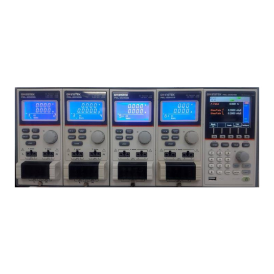
- Page 1 Programmable DC Electronic Load PEL-2000B Series USER MANUAL ISO-9001 CERTIFIED MANUFACTURER...
- Page 2 This manual contains proprietary information, which is protected by copyright. All rights are reserved. No part of this manual may be photocopied, reproduced or translated to another language without prior written consent of the Good Will company. The information in this manual was correct at the time of printing. However, Good Will continues to improve products and reserves the right to change specification, equipment, and maintenance procedures at any time without notice.
-
Page 3: Table Of Contents
Table of Contents Table of Contents SAFETY INSTRUCTIONS ........... 6 GETTING STARTED ............10 Main Features ............12 Series Overview ............. 14 Package Contents and Accessories ......16 Measurement Overview ......... 17 Front Panel Overview ..........18 Display Overview – Mainframe ......23 Rear Panel Overview .......... - Page 4 PEL-2000B Series User Manual Parallel Load Modules ......... 103 Programming ............105 Sequences ............107 Frame Link ............108 Channel Control ........... 110 General Configuration Options ......112 OPERATION ..............114 Local Mode Operation ......... 117 Mainframe Basic Operation ......... 123 Creating a Program Sequence ......
- Page 5 Table of Contents INDEX ................312...
-
Page 6: Safety Instructions
Warning: Identifies conditions or practices that WARNING could result in injury or loss of life. Caution: Identifies conditions or practices that CAUTION could result in damage to the PEL-2000B series or to other properties. DANGER High Voltage Attention Refer to the Manual Protective Conductor Terminal... - Page 7 performed for CAT II, III and IV. (Measurement categories) EN 61010-1 specifies the measurement categories and their requirements as follows. The PEL-2000B series falls under category I. Measurement category IV is for measurement performed at the source of low-voltage installation.
- Page 8 2500V. (Pollution Degree) EN 61010-1 specifies the pollution degrees and their requirements as follows. The PEL-2000B series falls under degree 2. Pollution refers to “addition of foreign matter, solid, liquid, or gaseous (ionized gases), that may produce a reduction of dielectric strength or surface resistivity”.
- Page 9 SAFETY INSTRUCTIONS condensation which is expected. In such conditions, equipment is normally protected against exposure to direct sunlight, precipitation, and full wind pressure, but neither temperature nor humidity is controlled. Location: Indoor Storage environment Relative Humidity: < 80% Temperature: −10°C to 70°C ...
- Page 10 PEL-2000B Series User Manual ETTING STARTED This chapter describes the features and functions of the PEL-2000B series, including the front and rear panel appearance, panel installation and connection types. Use the Tutorial section for quick access to step by step instructions on the main functions.
-
Page 11: Getting Started
GETTING STARTED Precautions and Procedures ........... 43 Remote (Sense) Connection ........... 48 Single Load Connections ..........49 Parallel Load Connections ..........51 Frame Link Connection .......... 53 Channel Control Connection ........55 Go/NoGo Connection ..........58... -
Page 12: Main Features
The flexible module configuration allows the mainframes to either sink multiple loads independently or large loads when used in parallel. The PEL-2000B series support four operation modes: constant current (CC), constant voltage (CV and CV+CC), constant resistance (CR) and constant power (CP). Constant current and constant resistance mode can operate in either static or dynamic mode. - Page 13 GETTING STARTED 4 panel setups. USB flash drive support. Interface RS-232C/RS485 GPIB (optional) ...
-
Page 14: Series Overview
PEL-2000B Series User Manual Series Overview The PEL-2000B series comprises of two different Mainframes: the PEL-2002B and the PEL-2004B. The Mainframes differ by the number of load modules that can be accommodated. The PEL- 2002B has two load module slots whilst the PEL-2004B has 4. There are 4 different load module models, the PEL-2020B, PEL-2030B, PEL-2040B and PEL-2041B. - Page 15 GETTING STARTED Load Module Channels Power (W) Current (A) Voltage (V) CH L/R Range (low/high Low/High range) PEL-2020B 100/100 2/20 0-80 (100Wx2) PEL-2030B 30/(25/250) 5/4/40 0-80 (30/(25/250W)) PEL-2040B (35/350) 7/70 0-80 PEL-2041B (35/350) 1/10 0-500...
-
Page 16: Package Contents And Accessories
Description Accessories Power Cable Mains power cable (region dependent) (18AWGx3C,125V/10A,1.8m) CD ROM Contains PEL-2000B series Electronic DC Load User Manual, Programming Manual and USB Driver GTL-120 Load cables 2X red, 2X black (per load module) GTL-121 Remote sense cables , 1X red, 1X black (per load channel) PEL-003 3 sets for PEL-2004B;... -
Page 17: Measurement Overview
GETTING STARTED Measurement Overview The PEL-2000B series has a number of different operating modes that are completely configurable. All the modes have customizable Go/NoGo limits, range limits, timers, slew rates, alarms and protection limits. For parallel loads, there is a dedicated Parallel configuration mode. -
Page 18: Front Panel Overview
PEL-2000B Series User Manual Front Panel Overview PEL-2002B DC Electronic Load LCD display Function keys LOCAL UTILITY System Keys CHAN FUNC FILE HELP Selector Knob Number Pad PRESET SHIFT Operation CAL. LOCK keys ON / CLEAR ENTER LOAD USB input Power 320 by 240, TFT LCD display. - Page 19 GETTING STARTED Brings up the LOCAL Channel Menu. CHAN Used to activate local control mode LOCAL LOCAL during remote CHAN SHIFT SHIFT CHAN control via the interface Used to access the Program, Sequence or OCP automation FUNC menu. Used to access the File menu. FILE Brings up the Help menu and UTILITY...
- Page 20 PEL-2000B Series User Manual Decimal point. CAL. Activate calibration CAL. SHIFT SHIFT mode. Please note, calibration mode is not supported. Please see your distributor for calibration needs. Note Clears current values. Alternative LOCK function locks the keys and the CLEAR Selector knob.
- Page 21 GETTING STARTED Saves and recalls preset settings Operation Keys PRESET and values. When pressed in combination with the number pad, Presets P0- P9 can be recalled or saved. Inactive PRESET Active. Used in PRESET combination with the number pad and/or shift key. Press to recall a channel preset PRESET...
- Page 22 PEL-2000B Series User Manual Active. When SHIFT active the shift key can be used to access the Local and Utility menus. Coarse control SHIFT SHIFT mode. Fine control mode SHIFT SHIFT Confirms selections. ENTER Turns the current load/channel on LOAD...
-
Page 23: Display Overview - Mainframe
GETTING STARTED Display Overview – Mainframe Mainframe 05/04/22 Status 16 : 50 Alarm Panel A Value 80.00 V *CH1 B Value 80.00 V Curr Limit 40.00 A Current Main SPEC Operation Screen Slow Channel Status main Panel Mode Range Response Menu Configure Configure... - Page 24 PEL-2000B Series User Manual Load Type The Load Type Icon LOAD LOAD indicates if a Sequence (SEQ) or Program (PROG) is turned on. If PROG PROG not then LOAD is displayed as default. When any Load type is running, their icon will turn orange.
- Page 25 GETTING STARTED Channel CH1~ CH8 Displays the current channel. * = independent mode *CHx S = Group channels CHxS Sync mode CHxP P = Group channels Parallel mode Mode Displays the current mode. CC Static Low Range CC Static High Range CCDL CC Dynamic Low Range CCDH...
- Page 26 PEL-2000B Series User Manual Channel When Channel Control is set Control to External, EXT will be displayed. Voltage Displays the voltage range of the Range current setting. Menu Shows the current menu. main = Chan menu conf = ChanConfigure menu s_edit = ChanSeq.Edit menu...
-
Page 27: Rear Panel Overview
GETTING STARTED Rear Panel Overview PEL-2004B Go/NoGo Output GPIB GO / NG OUTPUT GPIB port SER. NO. LB FRAME CONT RS232/ RS485 RS-232C/ RS-485 port Disconnect power cord before replacing fuse. Débranchez le cordon 100 - 120 VAC d'alimentation avant de 200 - 240 VAC remplacer le fusible. - Page 28 PEL-2000B Series User Manual The GPIB port is used for remote GPIB port control connections. GPIB: 24-pin female See pages 269 for remote control details. Ethernet port for controlling the PEL- LAN port 2000Bremotely. See pages 237 for remote control details.
- Page 29 GETTING STARTED The power supply socket accepts the Power Socket/ AC mains Voltage. The fuse holder is Fuse located below the power socket. Power: 47~63Hz Fuse: T3.15A/250V For fuse replacement details see page 284. Each channel has a dedicated Channel Channel CH CONT 1 control port to enable external monitoring...
-
Page 30: Front Panel Overview - Load Module
PEL-2000B Series User Manual Front Panel Overview – Load Module DC Electronic Load L 20A / 80V , 100W PEL-2020B 20A / 80V , 100W LED display Static/ Dynamic R/L A/B Key STATIC/ R / L DYNA. Display Key Slave Knob... - Page 31 GETTING STARTED Power Load time Activates the load for the active Load Key LOAD channel. (Right or Left)(A or B) V sense The voltage sense terminals are Left Voltage used when precise measurement is Sense needed. V Sense terminals are used 80V DC to compensate for voltage drops V sense...
- Page 32 PEL-2000B Series User Manual The STATIC/DYNA. Key manually Static/Dynamic STATIC/ switches the load from Static Selector Key DYNA. (manual) to Dynamic loads. Dynamic loads are only supported in CC and CR mode. For more information see page 60 & The Slave Knob is used to edit and...
-
Page 33: Led Display Overview - Load Module
GETTING STARTED LED Display Overview – Load Module & Channel Display Left and right channel indicator. 5 digit display. Indicates the channel number & (1-8). Channel Number Indicator Indicates if the load is active on the load module. (Dual channel load modules) Indicates if the load is on for single channel load modules. - Page 34 PEL-2000B Series User Manual The Mode Indicator LEDs will indicate what the current mode or settings are on the active Mode Indicator channel(s). Value A or B for a single channel load module. Applies to CR, CV, CP and CC static mode only.
- Page 35 GETTING STARTED Lights up when Go/NoGo is activated and the load fails (NG) the Go/NoGo limits. The Unit Indicators display the current & unit. Channel Unit Indicators Voltage Resistance Current Power Second...
-
Page 36: Installation
PEL-2000B Series User Manual Installation The installation chapter describes how to load the different load modules, install the optional GPIB card, the rack mount kit and how to determine each channel number. If you need to move all installed device to another location, please disassembly the modules first, and then reassembly the modules after moving to the desired location. - Page 37 GETTING STARTED 3. Use the supplied screw to fix the module to the load slot, located under the load terminals. 4. Install any additional modules as described above. 5. If there are any slots empty, install the supplied panel cover (part number: PEL-003). The panel cover will improve safety and increase air flow.
-
Page 38: Gpib Installation
PEL-2000B Series User Manual GPIB Installation To avoid static electricity, please use appropriate anti- WARNING static work practices. The PEL-2004B/PEL-2002B has GPIB as an option GPIB Card (part no. PEL-001). installation Steps 1. Ensure the mainframe is disconnected from mains power. -
Page 39: Rack Mount Installation
GETTING STARTED Rack Mount Installation The PEL-2004B can be used in a standard 19” rack Background mount enclosure with the optional rack mount kit (part no. 11EL-20040201). Each unit requires a rack height of 4U with a 1U space for ventilation top and bottom. -
Page 40: Channel Number
PEL-2000B Series User Manual Channel Number The channel number for a module load is Description determined by which slot it occupies on the mainframe chassis. There can be 1 or 2 channels per slot, depending on the load module type. -
Page 41: Power Up & Self Test
GETTING STARTED Power Up & Self Test 1. Connect the power cord Panel operation to the power socket. 2. Turn the external power switch on. 3. Hold the power button on the front panel to turn on the power. The power button turns green from red (standby). - Page 42 PEL-2000B Series User Manual Initial System Success Success Success Success Success Success When the system check happens, the load modules will display each channel as it is checked, then display the current mode. 4. If any of the System checks fail, please power down the load and reinstall the appropriate load module(s).
-
Page 43: Load Connections
Single DUT, parallel load Multiple DUTs, multiple loads Multiple DUTs, multiple mainframe loads Single DUT, parallel mainframes The PEL-2000B series also supports a number of different control methods and interfaces. The connections used are described here: Frame link ... - Page 44 13.1 17.2 22.6 30.4 40.6 55.3 When using the PEL-2000B series, voltage drop Load Line and voltage generated due to load line inductance Inductance Considerations and current change must be taken into account. Extreme changes in voltage may exceed the minimum or maximum voltage limits.
- Page 45 GETTING STARTED Current ∆I time ∆T Voltage Min. V time The diagram above shows how changes in current can affect voltage. Load line inductance can be reduced by ensuring Limiting Load line load wires are as short as possible and by twisting inductance positive and negative load wires together.
- Page 46 PEL-2000B Series User Manual The PEL-2000B series supports single and dual Load module channel load modules. considerations Single channel load modules have one bank of negative terminals and one bank of positive terminals. Each terminal pair has a 40A capacity.
- Page 47 GETTING STARTED 4. Close the terminal cover securely. Ensure the wires are secured properly and that the wires are not exposed when the cover is in place. Ensure that the wires are tied or twisted together to WARNING prevent noise and inductance. Ensure the polarity is correct before proceeding with CAUTION any connections.
-
Page 48: Remote (Sense) Connection
PEL-2000B Series User Manual Remote (Sense) Connection The electronic load modules have two voltage Background sense contacts: Vsense +, Vsense -. Voltage sense can be used to help compensate for long cable length. The longer the cable, the higher the potential resistance and inductance, therefore a short cable is best. -
Page 49: Single Load Connections
GETTING STARTED V sense 80V DC Single Load Connections A dual channel load module can be used to sink Dual Channel two loads concurrently. Load Module Connection Dual channel Twisted Load Module Pair Twisted Pair On a single channel load module, the left Single Channel Load Module terminals are both negative (-), whilst the right... - Page 50 The diagram below shows a typical connection. Load Module Auxiliary Using an auxiliary power supply may induce reverse WARNING current. The PEL-2000B series has reverse voltage protection. For details see the protection section on page 82.
-
Page 51: Parallel Load Connections
80 for a description on parallel dynamic loading). Note that the same modules must be used when operating the parallel. The PEL-2000B series also features a dedicated parallel configuration setting known as Group Unit. When Group Unit is turned on, load modules of the same type and rating to be used in parallel for CC and CR mode. - Page 52 Master Slave Slave Slave Slave The PEL-2000B series is also able to sink a number Multi-output of loads concurrently from multiple DUTs or sink power supply load a number of loads from the same DUT (i.e. multiple output power supply).
-
Page 53: Frame Link Connection
GETTING STARTED Frame Link Connection Frame link control involves connecting multiple Background mainframes using the frame link connections. Up to 4 slave mainframes can be connected to the master mainframe. The first mainframe (master) can be used to control the other slave frames. There is a delay time of 2µs between the master and first slave mainframe, and 4µs, 6µs, and 8µs to the second, third, and fourth slave mainframes,... - Page 54 PEL-2000B Series User Manual The first mainframe that is connected is the master frame; any additional frames are slave units. The ribbon cable connects to the master from connector 2, and the slave from connector 1. Each successive slave unit is connected in a cascading manner the same way.
-
Page 55: Channel Control Connection
GETTING STARTED Channel Control Connection The Channel Control connecters are located on the Background rear panel of each mainframe. There are two channel control connectors for each load slot, one for each channel, if applicable. The channel control connector is used to externally: Turn on/off loads. - Page 56 PEL-2000B Series User Manual EXT VREF Twisted External Pair Voltage Ensure the external voltage reference is stable and WARNING has low noise. The External Voltage should be no more than 10V. No more than 12 volts may be used as an external voltage.
- Page 57 GETTING STARTED +15V Reference voltage V MON I MON Voltage Monitor Current Monitor The channel control connector is a screw less Connector clamp connector. The internal clamp mechanism Connection must be opened before a wire can be inserted. To open the internal clamp, push the button above the wire socket, to close, release the button.
-
Page 58: Go/Nogo Connection
PEL-2000B Series User Manual Go/NoGo Connection The Go/NoGo port is a 15 socket port. Each Background channel has a dedicated line for a Go/NoGo output. The ports are open-collector with active high (30V) indicating a pass and active low (1.1V) as fail (an alarm). -
Page 59: Operating Description
OPERATING DESCRIPTION PERATING DESCRIPTION Operating Mode Description ......... 60 Constant Current Mode ..........60 Constant Resistance Mode ..........63 Constant Voltage Mode ..........65 Constant Power Mode ............ 68 Group Unit Mode ..........70 Run Program ............72 Sequence ............... 75 OCP Test Automation .......... -
Page 60: Operating Mode Description
PEL-2000B Series User Manual Operating Mode Description There are four basic operating modes: constant current (CC), Constant Resistance (CR), Constant Voltage (CV/CV+CC) and Constant Power (CP). All channels operate using any of the modes. Each mode has a number of configurable options including slew rate, levels, protection modes, Go/NoGo and extensive save options. - Page 61 OPERATING DESCRIPTION Static Functions Static mode tests the stability of the voltage output from a power source. Single channel load modules can have two 2 current levels A (A Value) & B (B Value). A & B have the same range. Pressing the A/B key on the module load will cycle through the A and B states.
- Page 62 PEL-2000B Series User Manual The slew rate is the rate at which the current will Slew rate increase to a set level. There are two slew rates: rising slew rate & falling slew rate. In CC mode the slew rate is defined as A/uS.
-
Page 63: Constant Resistance Mode
OPERATING DESCRIPTION CC Mode: Dynamic:Go/NoGo Current Level 1 Level 2 NoGo Voltage GO is specified as between the Low and High Go/NoGo limits. NoGo is specified as outside the Go/NoGo limits. Constant Resistance Mode In Constant Resistance Mode the load units will Background linearly sink current and voltage to match a set resistance. - Page 64 PEL-2000B Series User Manual Resistance Range There are two ranges: High and Low. The Low range is used for low voltage ranges, whilst the High range uses high voltage ranges. The current range always remains in High range, regardless of the selected resistance range.
-
Page 65: Constant Voltage Mode
OPERATING DESCRIPTION The rising and falling slew rate (A/uS) determines Slew Rate the speed at which the load levels change from A to B Value (Static mode) or from Level1 to 2 (Dynamic mode) and vice versa. Go/NoGo is also supported. Center, High and Go/NoGo Low limits can be set as either percentages or voltage values. - Page 66 PEL-2000B Series User Manual CV Mode Load Current Load Input Voltage Two voltage levels can be set: A & B (single Voltage levels channel load module). CV Mode Voltage A value B value Time When using CV mode, a current limit can be set CV + CC for CV + CC mode.
- Page 67 The PEL-2000B series will try to rectify any voltage drops. However if voltage drops are too large, they may cause the load to go into oscillation.
-
Page 68: Constant Power Mode
PEL-2000B Series User Manual Constant Power Mode In Constant Power Mode the load units will Background ensure a constant power load for the power supply. Single channel load modules support 2 values (A Value, B Value) and have an adjustable cut-off current limit. - Page 69 OPERATING DESCRIPTION When using CP mode, a current limit can be set CP + CC for CP + CC mode. When the constant power current is less than current limit, the channel will operate in CP mode. When the constant power current exceeds the current limit, the channel will operate in CC mode.
-
Page 70: Group Unit Mode
PEL-2000B Series User Manual Group Unit Mode The Group Unit menu allows load modules of the Background same type and rating to be configured as a single unit when used in parallel. This saves the hassle of configuring each channel individually. - Page 71 OPERATING DESCRIPTION Para mode Sync Mode 05/04/22 05/04/22 LOAD LOAD 16 : 50 16 : 50 Level1 Level1 CH1P CH1S Level2 CCDH Level2 CCDH SlewRate 0.80 A/uS SlewRate 0.80 A/uS SlewRate 0.80 A/uS SlewRate 0.80 A/uS Timer1 0.025 Timer1 0.025 Timer2 0.025 Timer2...
-
Page 72: Run Program
PEL-2000B Series User Manual Run Program The Program function on the PEL-2000B series Background supports a total of 12 different programs at any one time with 10 sequences to each program. Up to 12 programs can be chained together. The Program function is able to create a number of Go/NoGo tests. - Page 73 OPERATING DESCRIPTION Sets the running configuration for the current sequence. The sequence can be skipped, run or run manually only. Range: Auto | Skip | Manual On-Time Sets the Sequence Run On-Time Range: 0.1 ~ 60.0s Off-Time Sets the Sequence Off-Time Range: Off | 0.1 ~ 60.0s Short-time Sets whether the Short-Time for...
- Page 74 PEL-2000B Series User Manual Any of the 12 programs can be chained together to Program Chain create a Program Chain. Unlike Program Sequences, Program Chains need not be run sequentially in numerical order. Any program can be chained to any program. It is possible to chain programs into an infinite loop to continue a program indefinitely.
-
Page 75: Sequence
OPERATING DESCRIPTION Sequence The Sequence function is used to create high Background resolution load simulations. Each Sequence can be configured to create a unique load profile to accurately simulate loads in real time. Sequences are only applicable for CC (Static) and CR (Static) modes. - Page 76 PEL-2000B Series User Manual Up to 120 points can be used with each Sequence. Points Each point can have a different duration, slew rate and value. A new point can be inserted or deleted at any stage of a Sequence. Any new points that are inserted will have a value averaged from its neighbors as default.
- Page 77 OPERATING DESCRIPTION If more than one Sequence is programmed on the On End Of Seq. mainframe, the On End Of Seq. function will hold function the load current (of the selected sequence) to a designated value until all the other sequences have finished running.
- Page 78 PEL-2000B Series User Manual As can be seen above, a trigger sequence signal is output for every rising edge point. The Trigger In setting allows a sequence to start Trig In after a trigger (Trig Out) has been received via the frame link connector.
- Page 79 OPERATING DESCRIPTION CH1 import CH2 Value Time...
-
Page 80: Ocp Test Automation
The PEL-2000B series also has a user-defined OCP setting in the event that the power supply OCP fails. -
Page 81: Parallel Dynamic Loading
OPERATING DESCRIPTION Parallel Dynamic Loading The PEL-2000B series of DC electronic loads Background support parallel dynamic loading. This simply means that when the load modules of a mainframe are connected in parallel and set to dynamic mode, they can perform dynamic tests synchronously following the same clock. -
Page 82: Configurations Description
The Configuration Description section describes what the different configurations are used for and how they can be relevant to different operations. Protection Modes The PEL-2000B series include a number of Background protection modes: Over Current Protection, Over Voltage Protection, Over Power Protection, Under voltage protection and Constant Power Protection. - Page 83 OPERATING DESCRIPTION When a load unit is operating in CR, CV or CP Over Current mode, the unit may need over current protection to Protection prevent excessive current being set. Over current protection stops the load from sinking more current than its recommended limit which can cause damage to the unit.
-
Page 84: Operating Configurations
PEL-2000B Series User Manual Reverse voltage protection prevents reverse Reverse voltage voltage damage to the PEL-2000B series up to the Protection specified rating. When Reverse voltage protection has been tripped an alarm tone will sound until the reverse voltage is removed. - Page 85 OPERATING DESCRIPTION Von Latch: ON Von Latch: OFF Output Output time time PEL-2000B PEL-2000B series load series load load load time time As can be seen in the diagram below, when Von-Latch is set to off, the load module will start to sink current when the Von-voltage limit has been tripped.
- Page 86 (up to 10 seconds) after the load key has been pressed. However the Load D-Time setting will only work for loads that are initiated manually or when the PEL-2000B series mainframe is configured to Auto load (page 201) at run time. The Response setting sets the bandwidth of the Response load to 200Hz (normal) or 20kHz (fast).
- Page 87 OPERATING DESCRIPTION The step resolution parameters apply to the following: CCH Step – CC high range CCL Step – CC low range CRH Step – CR high range CRL Step – CR low range CVH Step – CV high range CVL Step –...
-
Page 88: Channel Control
PEL-2000B Series User Manual function must be used in the case of Load ON. When setting to OFF, the short function can be used directly. A short circuit may trip a protection mode if too Note much current is sunk. - Page 89 OPERATING DESCRIPTION External Voltage Control 100% Voltage/ Current Setting (Percent Rating) External Voltage To determine the Percent Rating (voltage or current load input), use the following formula; External Voltage Load Input Rating VorA Where “Rating V or A” is the rating voltage/current of the load module.
- Page 90 PEL-2000B Series User Manual Voltage Monitor The input voltage, like the load input current can be externally monitored with the channel control connectors. The VMON pin of the channel control connector outputs a voltage of 0~10V to represent the load input voltage as a percentage (0~100%) of the rating voltage.
-
Page 91: Interface And System
GPIB configuration Page 226 GPIB pin configuration Page 269 USB configuration Page 224 File System The PEL-2000B series is able to save and recall a Background number of different data types for each channel: Presets Memory Setup SEQ (Sequence) All data types can be saved and recalled to... - Page 92 PEL-2000B Series User Manual Each channel has its own dedicated memory for each data type. Thus files are saved/recalled for each channel and each data type. Preset data can be saved into 10 memory slots for Preset Data each channel. Preset data contains the mode, range, CV response speed and Go/NoGo settings.
- Page 93 OPERATING DESCRIPTION SEQ data contains Sequence data. SEQ data can SEQ Data only be saved to and from USB. SEQ refers to Sequence data, not Program sequences. Internal Format N/A (Internal buffer) External Format 20X0X_XX.A SEQ Contents SEQ data contains the following data; Seq.Edit No.
- Page 94 PEL-2000B Series User Manual Range CV response speed Go/NoGo SPEC Test Entry Mode High Center When saving data to internal memory, either the Save: Internal current channel or all the channel data can be memory saved.
- Page 95 OPERATING DESCRIPTION Save/Recall USB In order to save data from a single channel to USB, data must first be saved to the internal memory. After data is saved to internal memory, all the files can be saved to USB. Channel X Internal Memory File.M Memory Data...
-
Page 96: File Format
PEL-2000B Series User Manual File Format Current Channel Filename format Memory data 1: PEL-2000B series Load module 2030R_00.M Preset data type: SEQ data 1 2 3 4 2020 = PEL-2020B 2030 = PEL-2030B 2040 = PEL-2040B 2041 = PEL-2041B 2: Channel location or Voltage range of single channel model. - Page 97 OPERATING DESCRIPTION All Channel File Format Memory data 1: PEL-2000B series Load module 2230R_C1.M Preset data type: SEQ data 2 3 4 2020 = PEL-2020B Setup Data 2030 = PEL-2030B 20040_00.S 2040 = PEL-2040B, 1 2 3 4 2041 = PEL-2041B...
-
Page 98: Tutorials
PEL-2000B Series User Manual UTORIALS Local loads ............99 Single Channel Load ..........101 Parallel Load Modules ......... 103 Programming ............105 Sequences ............107 Frame Link ............108 Channel Control ........... 110 General Configuration Options ......112... -
Page 99: Local Loads
TUTORIALS Local loads Local mode operation is useful to quickly test loads using the load module control panel rather than the mainframe control panel. Local load modules can be configured to operate independently to the mainframe. This can be useful when settings need to remain unchanged on the mainframe. - Page 100 PEL-2000B Series User Manual The local load modules can be set Page 185 Independent to independent load. load Slave knobs can be configured to Page 206 Independent control be independent to the mainframe. Display Measured or Set Values Page 209 10.
-
Page 101: Single Channel Load
TUTORIALS Single Channel Load Single channel loads are used to manually test a DUT quickly or to configure channel settings for Program Sequences using the mainframe panel. Step Description Details Choose the appropriate load Page 36 Setup module and make sure it is installed. - Page 102 PEL-2000B Series User Manual Set the A(B) Value, slew rate (CC, CC Page 129 Static Values CR) and current limit (CV, CP) CR Page 136 (CC, CR, CV, CV Page 139 CP Page 143 Set the Go/NoGo configurations, Page 191 Go/NoGo if applicable.
-
Page 103: Parallel Load Modules
TUTORIALS Parallel Load Modules The Group Unit setting allows for a quick and easy parallel setup for load modules of the same type and rating. However, the Group Unit settings only apply for CC and CR modes. Step Description Details Choose the appropriate load Page 36 Setup... - Page 104 PEL-2000B Series User Manual Set the Go/NoGo configurations, Page 191 Go/NoGo if applicable. Configure the protection modes. Page 174 10. Protection Modes Activate the load by pressing the 11. Run LOAD load key. Optional 12. Configuration There are number of...
-
Page 105: Programming
TUTORIALS Programming When creating a Program Sequence or Chain, all channels are used at the same time unless programmed otherwise. Program Sequences use the channel settings stored from Memory Data. Program sequences are primarily used to perform a battery of pass/fail tests on DUTs. - Page 106 PEL-2000B Series User Manual 11. Save Program Save the chain in the Chain menu. Save everything to the internal Page 236 12. Save Setup Setup memory. Run the Program Page 153 13. Run Sequence/Chain.
-
Page 107: Sequences
TUTORIALS Sequences Sequences are used to accurately simulate loads. As each Sequence is independent, Sequences are ideally suited to test multiple output power sources. Step Description Details Choose the appropriate load Page 36 Setup module(s). Connect the terminals to the DUT. Page 43 Connection Select a load channel with the Page 123... -
Page 108: Frame Link
PEL-2000B Series User Manual Frame Link Frame link connections are used connect up to four slave main frames to a master main frame. When using frame link connections it is possible to perform a number of operations in parallel under the control of the master unit. - Page 109 TUTORIALS Run the loads. To run the loads, LOAD press the LOAD key on the master mainframe. To stop, press again. When the LOAD key is pressed all loads will be active. Options Load preset memory on the Page 263 Load Preset mainframe and all frame-linked memory...
-
Page 110: Channel Control
Connect the terminals to the DUT. Page 43 Connection Connect the channel control Page 55 & 271 connectors on the rear panel. Turn on the PEL-2000B series mainframe and DUT (load). Select the Mode* and Range* via CC Pages 125, Configure the front panel. - Page 111 TUTORIALS Run the load. Turn the load on by Page 55 & 87 either outputting an active low signal to the appropriate channel control connector or control connector, or press the LOAD key on the load module or mainframe**. Use IMON and VMON to monitor Page 87 Monitor the current and voltage of load...
-
Page 112: General Configuration Options
PEL-2000B Series User Manual General Configuration Options There are number of different options for each channel. The different options are described below. Options Description Details Configure the CC Voltage range Page 178 CC Vrange from high or low. Configure the Von Voltage settings. Page 179 Von Voltage Configure the short key settings. - Page 113 TUTORIALS Turn the sound on/off for the Page 202 14. Sound mainframe IU.
- Page 114 PEL-2000B Series User Manual PERATION The PEL-2000B series operation is described in the chapters below. The sections are broken down into small operations. For thorough examples on the operation of the load, please see the tutorial section on page 99.
-
Page 115: Operation
OPERATION Select CP Range ............145 Creating a Program Sequence ......146 Program Chains ............150 Running a Program ............153 Edit Sequence ............. 158 Create Sequence Loop ..........160 Channel Duration Time Settings ........162 Run Sequence ............... 165 OCP Test Automation .......... - Page 116 PEL-2000B Series User Manual Setting the Date and Time ..........220 Interface Configuration (settings) ....... 222 Configuring UART Connection ........222 Configuring USB Connection ........224 Configuring the GPIB Address ........226 UART, LAN and USB CDC Function Check ... 228 GPIB Function Check .......... 231 Saving/Recalling Channels ........
-
Page 117: Local Mode Operation
OPERATION Local Mode Operation Each channel can be edited by its local load module. Depending on the configuration, local changes can be reflected on the mainframe. For this section all operations refer to knobs and buttons on the local load module panels, unless stated otherwise. Selecting a Channel Each channel can be individually selected by Background... -
Page 118: Selecting Static/Dynamic
PEL-2000B Series User Manual Selecting Static/Dynamic Each load channel can be individually switched Background from Static to Dynamic using the local load module. 1. Select a channel on the load Page 117 module. 2. Press the STATIC/DYNA. key to Panel operation... -
Page 119: Turning On The Load
OPERATION Turning on the Load Loads can be individually selected to be turned on Background using local operation. 1. Select a channel on the load Page 117 module. 2. Press the LOAD key to turn on Panel operation LOAD the load. When a channel load is activated, the Note load on symbol will be displayed... -
Page 120: Shorting
PEL-2000B Series User Manual Shorting The Short Key is used to simulate a short circuit. Background 1. Configure the Short settings. Page 181 2. Select a channel on the load Page 117 module. 3. Press the SHORT key to enter the... -
Page 121: Editing Cc/Cr/Cv/Cp A/B Value
OPERATION Current Power Load on time. The Display mode cannot be changed in Group Unit Note mode. Editing CC/CR/CV/CP A/B Value The Slave Knob is used to edit the A Value or B Background Value (single channel load module) when in static mode. - Page 122 PEL-2000B Series User Manual When the Slave Knob is set to “Measure”, the slave Note knob must be pressed first to display the values on the load module display. Editing the A/B Value is not possible with this method in Group Unit mode.
-
Page 123: Mainframe Basic Operation
OPERATION Mainframe Basic Operation For the Mainframe Basic Operation section, all operations refer to the knobs and keys on the main configuration panel, unless otherwise stated. Help Menu When any function key has been pressed or when Background a menu has been opened, the HELP key can be used to display a detailed description. -
Page 124: Channel Selection
PEL-2000B Series User Manual 4. Press F5 to exit. Channel Selection There are up to 2 channels per load module, Background depending on the model. The main display can be used to control each channel individually. When Group Unit Mode is enabled, channel selection Note is disabled. -
Page 125: Select Cc Mode
OPERATION Select CC Mode The PEL-2000B series loads operate in four Background different modes: Constant Current (CC), Constant Resistance (CR), Constant Voltage (CV), and Constant Power (CP). When a channel is active, the F1 key can be used to switch between each operating mode. -
Page 126: Select Cc Dynamic Mode
PEL-2000B Series User Manual Panel Operation 1. Press the F2 (Range) key repeatedly until High or Low range is selected. Range Range High The range will be reflected in both the CH1P bottom menu system and the Current CCDH Operation Channel Status panel. -
Page 127: Editing Cc Dynamic Parameters
OPERATION Changing from static to dynamic mode will only affect Note the current (active) channel. Editing CC Dynamic Parameters Dynamic Constant Current Mode has two Background operating current levels, slew rates and timers. Slew rates determine the speed at which the load will change from one level to the next. - Page 128 PEL-2000B Series User Manual 05/04/22 16 : 50 Level1 0.80 CH1P CCDH Level2 0.50 SlewRate 0.80 A/uS SlewRate 0.80 A/uS Timer1 0.025 Timer2 0.025 main Range Mode Dynamic Configure Configure High 2. Press the Selector knob to edit the selected level, then turn to increase or decrease the value*.
-
Page 129: Select Cc Static Mode
OPERATION Select CC Static Mode Constant current mode can be set to dynamic or Background static mode. Static mode is for manually varying the load for single channel load modules or to set a static load on dual channel modules. Ensure the menu is in CC Mode. - Page 130 PEL-2000B Series User Manual A Value 0 ~ Setting Max A Parameters B Value 0 ~ Setting Max A SlewRate Load module dependent SlewRate Switch Value A/B (Group Unit Mode only) When Group Unit Mode is enabled, the A Value & B...
-
Page 131: Set To Cr Mode
*Press Shift to toggle between coarse and fine adjustment when editing the A Value and B Value parameters. See page 188 for details. Set to CR Mode The PEL-2000B series load operates in four Background different modes, Constant Current (CC), Constant Voltage (CV), Constant Resistance (CR) and Constant Power (CP). -
Page 132: Select Cr Range
PEL-2000B Series User Manual Mode Range Dynamic Configure Configure High Changing the operating mode will only affect the Note current (active) channel. Other channels will not be affected by any changes. Select CR Range Constant Resistance mode can run in high and Background low range. -
Page 133: Select Cr Dynamic Mode
OPERATION Select CR Dynamic Mode Constant Resistance mode can be set to dynamic Background or static mode. Dynamic mode is used to automatically set varying load rates. Ensure the menu is in CR Mode. See page 131. Mode Range Dynamic Configure Configure High... - Page 134 PEL-2000B Series User Manual Level1 Minimum ~ Rating Ω Parameters Level2 Minimum ~ Rating Ω SlewRate Load module dependent SlewRate Timer1 0.025 ~ 30000.0ms Timer2 0.025 ~ 30000.0ms When used in Group Unit Mode, the Level1 & Level2 Note range is the combined rating of all the units used in Group Unit Mode.
-
Page 135: Select Cr Static Mode
OPERATION Level1 100.000 Ω 3. Press the Selector knob or Enter ENTER to confirm selection. 4. Repeat steps 1-3 for the remaining parameters. Level1 & Level2 can be set for both High and Low Note Range. *Press Shift to toggle between coarse and fine adjustment when editing the Level1 and Level2 parameters. -
Page 136: Editing Cr Static Parameters
PEL-2000B Series User Manual Editing CR Static Parameters Single channel load modules have two resistance Background levels, A Value & B Value. Dual channel load modules have only one resistance level per channel, A Value. When Group Unit Mode is enabled, an additional parameter, Switch Value, is available to switch from A Value to B Value. - Page 137 OPERATION Single Channel Group Unit Mode Configuration Configuration 05/04/22 05/04/22 LOAD LOAD 16 : 50 16 : 50 A Value 100.000 A Value 100.000 Ω Ω CH1P B Value 100.000 B Value 100.000 Ω Ω SlewRate 0.40 A/uS SlewRate 0.40 A/uS SlewRate 0.40...
-
Page 138: Select Cv Mode
PEL-2000B Series User Manual Select CV Mode The PEL-2000B series electronic load operates in Background four different modes, Constant Current (CC), Constant Resistance (CR), Constant Voltage (CV), and Constant Power (CP). CV Mode cannot be used with the Group Unit mode. -
Page 139: Editing Cv Parameters
OPERATION Editing CV Parameters Constant Voltage mode can be set to a maximum Background limit (Curr Limit). Using the current limit enables limiting the current draw. When using CV mode on single channel load modules, two voltage levels can be set, A Value and B Value. -
Page 140: Select Cv Range
PEL-2000B Series User Manual 2. Press the Selector knob to edit the selected value, then turn to increase or decrease the value*. Use the number pad to enter a number. CAL. LOCK CLEAR A Value 10.00 3. Press the selector knob or Enter to ENTER confirm selection. -
Page 141: Select Cv Response Speed
OPERATION Range Range High The range will be reflected in both the bottom menu system and the Current Operation Channel Status panel. CV High Range CV Low Range Changing the range will only affect the current Note (active) channel. Other channels will not be affected by any changes. -
Page 142: Select Cp Mode
Note current (active) channel. Other channels will not be affected by any changes. Select CP Mode The PEL-2000B series electronic load operates in Background four different modes, Constant Current (CC), Constant Resistance (CR), Constant Voltage (CV), and Constant Power (CP). -
Page 143: Editing Cp Parameters
OPERATION Changing the operating mode will only affect the Note current (active) channel. Other channels will not be affected by any changes. Editing CP Parameters Constant Power mode can be set to have a Background maximum limit (Curr Limit). Using the current limit enables limiting the current draw. - Page 144 PEL-2000B Series User Manual 05/04/22 16 : 50 A Value 10.00 B Value 20.00 Curr Limit 7.140 main Range Mode Configure Configure 2. Press the Selector knob to edit the selected value, then turn to increase or decrease the value *.
-
Page 145: Select Cp Range
OPERATION Select CP Range Constant Power mode can run in high and low Background range. The maximum range is dependent on the load module. Some models are only high range. Ensure the menu is in CP Mode. See page 138. Mode Range Configure... -
Page 146: Creating A Program Sequence
PEL-2000B Series User Manual Creating a Program Sequence The PEL-2000B series has a total of 12 different Background programs and 10 sequences to each program. That totals to 120 different configurations. Each Sequence in each program uses the settings saved from Memory Data (Memory MXXX). - Page 147 OPERATION Memory M001~M120 Parameters Skip-Auto-Manual On-Time 0.1 ~ 60.0 seconds Off-Time Off – 0.1 ~ 60.0 seconds P/F Time Off – 0.1 ~ (On-Time+Off-Time)-0.1 Short-Time Off – 0.1 ~ On-Time Short Ch Off – 1~ 8 (CH1~CH8) Before a program can be created, the settings for Note each sequence for every channel that is to be used in the program must first be pre-configured and saved...
- Page 148 PEL-2000B Series User Manual 3. Press the selector knob to edit PROG:, then turn to select the program number. Use the number pad to enter a CAL. LOCK program number. CLEAR Program: 01 ~12 4. Press Enter or push the selector ENTER knob to confirm.
- Page 149 OPERATION Choose whether to run the sequence in the program automatically, skip the sequence or manually start the sequence. On-Time: 0.1 ~ 60.0 seconds Determines how long the sequence will run for (seconds). Off-Time: Off – 0.1 ~ 60.0 seconds Sets how long the sequence will stay off for (in seconds) between each sequence.
-
Page 150: Program Chains
On the PEL-2000B, there are up to 12 different Background programs containing 10 sequences. If 10 sequences in a Program Sequence prove to be inadequate for testing, the PEL-2000B series can chain different programs together, effectively making a larger Program Sequence. Unlike Program Sequences, Program Chains do not need to be run in numerical order. - Page 151 OPERATION Program Program Chain 1. Create 1 or more Program Panel operation Page 142 Sequences. 2. If Program Sequences were Page 237 created in a different session, ensure the programs have been loaded from Setup Memory. 3. Press the FUNC key, then FUNC Program (F1), followed by Chain (F1).
- Page 152 PEL-2000B Series User Manual 6. Use the Selector knob to choose the program that will execute after P01 (P02~P12). Select (Off) to end the Program Chain after (P01). Select (P01) to execute after P01, this will create a continuously looping Program Chain.
-
Page 153: Running A Program
OPERATION Running a Program Once a Program Chain/Program Sequence has Background been created, it can be executed. As Program Sequences apply to all the channels, any channels that don’t need to be active (load off) can be programmed in the Active Channel menu. At Default, all channels are set to (load) Off. - Page 154 PEL-2000B Series User Manual CH 01~08: ON (activate channel) – OFF (not activated) 5. Press Enter or push the selector ENTER knob to confirm the selection. 6. If needed, repeat steps 4-5 for the remainder of the channels. If all channels are Active OFF, a program cannot be Note run as there will be no channels active.
- Page 155 OPERATION 05/04/22 PROG 16 : 50 Start Run Program Program No: Seq (Memory) 10(001) GO GO Stop Next Configure As each sequence or program is completed the screen will update to display the active sequence/program. Notice that if a channel has been set up with Go/NoGo limits, a pass (GO) or fail (NG) will be displayed on the main display as well as the local load module display.
- Page 156 PEL-2000B Series User Manual 14. If Run was configured to manual in any of the program sequences, press F2 (Next) to continue the program sequence, otherwise the program will continue automatically. 15. Press F1 (Stop) at any time to abort the program when it is running.
- Page 157 OPERATION The Program (P) and Sequence (S) numbers for the Program are displayed on the left hand side and the Go/NoGo (G/N) results are displayed on the right hand side for each channel in the program. Use the Selector knob to scroll down to view the remainder of the list if necessary.
-
Page 158: Edit Sequence
PEL-2000B Series User Manual Edit Sequence The Sequence function can be configured to create Background a unique load profile to accurately simulate loads in real time for single or multiple loads. Sequence can only be used with CC static or CR static modes. - Page 159 OPERATION 05/04/22 LOAD 16 : 50 Point 0.00 Value Duration Time 0.000025 SlewRate 2.80 A/uS 2.80 A/uS SlewRate s_edit Delete Previous Loop Configure Point Point Menu 3. Use the Selector knob to highlight Value. 4. Press the Selector knob to edit the Value, then turn to increase or decrease the value.
-
Page 160: Create Sequence Loop
PEL-2000B Series User Manual Add Point will insert a new point directly after the Note current point. The value of the current/resistance of the inserted point will be the average of the point before and after. All other settings will remain unchanged. - Page 161 OPERATION Ensure the menu is in the Seq. Edit menu and that a sequence has been created. See page 158 Delete Previous Loop Configure Point Point Menu Repeat 1~9999/Infinity (0) Parameters Start of Loop 001~ last point On End of Seq. OFF / Setting Min ~ Setting Max CC Vrange High/Low...
-
Page 162: Channel Duration Time Settings
PEL-2000B Series User Manual 3. Press the Selector knob to edit Repeat, then turn to increase or decrease the value. 4. Use the number pad to enter a number. CAL. LOCK CLEAR Select 0 to choose infinity. Repeat 0005 Times 5. - Page 163 OPERATION The Trigger In signal is used to start any sequence that has TRIG set to IN. The trigger input signal is input via PIN4 of the first frame link connector (slave). For more details, see page 75. Any channels with channel control (CH CONT) set to external will be shown on the right side as EXT.
- Page 164 PEL-2000B Series User Manual 3. Press the Selector knob to edit the channel, and then turn to choose which channel’s Duration Time Setting to import. Range Ch 01~08 / OFF 4. Press the Selector knob or Enter ENTER to confirm selection.
-
Page 165: Run Sequence
OPERATION Run Sequence Like Programs, Sequences must be turned “ON” Background before they can be run. When running a Sequence, the front panel function keys, number pad, operation keys and selector knob are disabled for the specific channel(s). The load module panel is also disabled (bar the display key) for the specific channel. - Page 166 PEL-2000B Series User Manual 2. Press Seq. (F1) to turn on the Sequences. 3. SEQ will be displayed on the Mainframe Status panel. 05/04/22 16 : 50 4. Press the LOAD key to run all the LOAD Sequences. If a channel has TRIG set to IN, that channel will now wait for a trigger before running.
-
Page 167: Ocp Test Automation
OPERATION OCP Test Automation The OCP test function creates an automatic test to Background test the OCP of power supply products. Active Channel Applies the setting to the Parameters load channel. Range High(CC Mode High) or Low(CC Mode Low) Start Current(Start C) Starting current value for the test. - Page 168 PEL-2000B Series User Manual Last Current(Last_C) Sets the final current value after OCP has been tripped. This is the steady- state current draw after the OCP has been tripped. Step Time(Step_T) Sets the execution time of each step. (50mS to 1600S)
- Page 169 OPERATION 05/04/22 16 : 50 Chan: OCP Function Range: High Step_T: 0.05 Start C: 0.000 Delay: 0.000 End C: 71.400 Trig_V: 0.0000 Step_C: 0.002 Keep_T: 0.000 Last_C: 0.000 Active Configure Channel 2. Use the Selector knob to highlight the parameter you want to edit. 3.
- Page 170 PEL-2000B Series User Manual 05/04/22 16 : 50 Chan: OCP Function Range: High Step_T: 0.05 Start C: 0.000 Delay: 0.000 End C: 71.400 Trig_V: 0.0000 Step_C: 0.002 Keep_T: 0.000 Last_C: 0.000 Active Configure Channel 7. To select the load channels for the Select Active test, press Active Channel (F2).
- Page 171 OPERATION 8. Use the selector knob to Enter key ENTER to turn the Active value to ON. 9. Press Save (F3) to save the OCP Save the OCP Test Automation test automation channel. Channel 10. Press Previous Menu (F5) to return to the OCP Test Automation menu.
- Page 172 PEL-2000B Series User Manual Test Results 05/04/22 16 : 50 Run OCP Test 4.8550V 1.10A 4.8550 Configure Voltage Reading: The voltage of the DUT before the OCP was triggered. Current Reading: The current of the DUT before the OCP was triggered.
-
Page 173: Channel Configuration
OPERATION Channel Configuration The Channel Configuration chapter describes the configuration options for individual channels. Any configuration settings that are changed only apply to the current channel, other channels will not be changed. Accessing the Configuration Menu The configuration menu is used to access Background instrument settings and properties as well as set the protection levels for each channel. -
Page 174: Setting (Ocp/Ovp/Opp/Uvp)
PEL-2000B Series User Manual Setting (OCP/OVP/OPP/UVP) Over Protection is used to set the voltage, current Background or power limit. In the event that the current, voltage or power exceeds the over protection settings, the load module display will show an error message and beep an alarm. - Page 175 OPERATION Ensure the menu is the configuration menu. See Panel operation page 173. Previous Protection Other Go-NoGo Group Configure Menu 05/04/22 LOAD 16 : 50 OCP Level 71.400 CCDH OCP Setting OVP Level 81.6 OVP Setting OPP Level 357.00 OPP Setting conf Previous Protection...
- Page 176 PEL-2000B Series User Manual 6. Use the selector knob to turn ON, OFF or CLEAR the OCP Setting. 7. Repeat steps 1-5 for : OCP Level OPP Setting OVP Level UVP Level OVP Setting UVP Setting OPP Level Clearing an Alarm When any of the protection settings are tripped, Alarm will be shown on the Mainframe Status Panel and an alarm tone will sound by default.
-
Page 177: Protection Clear
OPERATION *REV, OTP and CPP cannot be cleared using this Note method, the Protection Clear function must be used instead, see page 177. See pages 58 and 276 to output alarms via the Go/NoGo output terminal. The configuration settings only apply to the current channel. -
Page 178: Setting The Cc Voltage Range
PEL-2000B Series User Manual Ensure the menu is in the configuration menu. See Panel operation page 173. Previous Protection Other Go-NoGo Group Configure Menu 1. Turn the load off by pressing the LOAD load key if necessary. 2. Use the selector knob to scroll down to Protection Clear. -
Page 179: Adjusting The Von Voltage And Latch
OPERATION 05/04/22 LOAD 16 : 50 CC Vrange High CCDH Von Voltage 0.00 Von Latch CH CONT Panel Independent Load D-Time 0.0 S conf Previous Protection Other Go-NoGo Group Configure Menu 2. Use the Selector knob to highlight CC Vrange. 3. - Page 180 PEL-2000B Series User Manual Von Voltage 0.0~Rating volts Parameters Von Latch ON/OFF Ensure the menu is in the configuration menu. See Panel operation page 173. Previous Protection Other Go-NoGo Group Configure Menu 1. Press the F2 (Other) key to enter the other menu.
-
Page 181: Configuring The Short Settings
OPERATION 4. Press the Selector knob or Enter ENTER to confirm selection. 5. Repeat steps 3 to 5 to turn Von Latch ON or For details about Von and Latch settings please see page 84. The configuration settings only apply to the current Note channel, other channels will not be affected. - Page 182 PEL-2000B Series User Manual 1. Press the F2 (Other) key to enter the other menu. 05/04/22 16 : 50 LOAD CVL Step 0.0004 CPH Step 0.01 CPL Step 0.001 Short Function Slow Short Key Toggle Short Safety conf Previous Protection...
-
Page 183: Configuring Channel Control
OPERATION 7. Press the Selector knob or Enter ENTER to confirm selection. 8. Use the Selector knob to highlight Short Safety. 9. Press the Selector knob to edit the selected setting, turn to change the setting. Short Safety 10. Press the Selector knob or Enter ENTER to confirm selection. - Page 184 PEL-2000B Series User Manual 05/04/22 LOAD 16 : 50 CC Vrange High CCDH Von Voltage 0.00 Von Latch CH CONT Panel Independent Load D-Time 0.0 S conf Previous Protection Other Go-NoGo Group Configure Menu 2. Use the Selector knob to highlight CH CONT.
-
Page 185: Configuring The Independent Setting
OPERATION Configuring the Independent Setting The Independent setting allows a channel to be Background load independent from the mainframe. What this means is that a load module with Independent set to ON can only load from the local load module. If the LOAD ON/OFF key is pressed from the mainframe, the channel with Independent set to ON will be unaffected by the mainframe, except... -
Page 186: Configuring The Load Delay Time
PEL-2000B Series User Manual 3. Press the Selector knob to edit the selected setting, turn to change the setting. Independent 4. Press the Selector knob or Enter ENTER to confirm selection. When a channel has been set to Note independent, an asterisk (*) will be... - Page 187 OPERATION 05/04/22 LOAD 16 : 50 Load D-Time CCDH Response Mormal CCH Step 0.002 CCL Step 0.0010 A CRH Step 0.00080 CRL Step 0.00080 CVH Step 0.002 conf Previous Protection Other Go-NoGo Group Configure Menu 2. Use the Selector knob to highlight Load D-Time.
-
Page 188: Configuring Step Resolution
PEL-2000B Series User Manual Configuring Step Resolution The CC, CR, CV and CP step resolution settings Background can be edited in the configuration menu. These step resolution settings directly correspond to the step resolution of the coarse adjustment when setting the CC, CR, CV and CP parameters. - Page 189 OPERATION CCH Step HR/40000 HR/2 Amperes A PEL-2030B (R) CCL Step LR/40000 LR/2 Amperes A Siemens ℧ CRH Step HR/40000 HR/2 Siemens ℧ CRL Step LR/40000 LR/2 CVH Step HR/40000 HR/2 Voltage V CVL Step LR/40000 LR/2 Voltage V CPH Step HR/25000 HR/2 Watt W...
- Page 190 PEL-2000B Series User Manual Use the Shift key to toggle between coarse and fine Note adjustment mode when editing the CC, CR, CV and CP values with the Selector knob on the main display. The fine adjustment resolution varies between the function and load module used.
-
Page 191: Configuring Response Time
OPERATION 3. Press the Selector knob to edit the selected setting, turn to change the setting. Use the number pad to enter a number. CAL. LOCK CLEAR CCP Step 0.002 4. Press the Selector knob or Enter ENTER to confirm selection. 5. -
Page 192: Go/Nogo
PEL-2000B Series User Manual 05/04/22 LOAD 16 : 50 Response Normal CCH Step CCDH 0.002 CCL Step 0.0010 A CRH Step 0.00080 CRL Step 0.00080 CVH Step 0.002 conf Previous Protection Other Go-NoGo Group Configure Menu 2. Use the Selector knob to scroll down to highlight Response. - Page 193 OPERATION Go/NoGo can be used in both high and low ranges, as well as CC, CV, CR and CP Modes. The Go/NoGo status can be read using the rear Go/NoGo output. A delay time can also be imposed for up to 1 second.
- Page 194 PEL-2000B Series User Manual Entry Mode Value Entry Mode Percent 4. The menu changes according to the selection. Value Percent 05/04/22 05/04/22 16 : 50 LOAD 16 : 50 LOAD SPEC Test SPEC Test CCDH CCDH Delay Time Delay Time...
-
Page 195: Group Unit
Up to 4 load modules can be used in this mode. Operating the PEL-2000B series load modules in Group Unit mode is almost identical to using the load modules separately. The only difference is... - Page 196 PEL-2000B Series User Manual Only CC or CR mode can be used in Group Unit. Note For the single channel load modules, PEL-2040B and PEL-2041B are fully support these two modes (Para, Sync) of group function. The PEL-2030B does not support group function.
- Page 197 OPERATION 4. Use the Selector knob to change Total Unit from the OFF setting to the number of parallel units. Total Unit 5. Press the selector knob or Enter to ENTER confirm. 6. To change the type of mode, use Parallel Mode the Selector knob to edit Group Mode.
- Page 198 PEL-2000B Series User Manual The PEL-2000B is now ready to operate in Parallel Mode. 10. To disable Parallel Mode, use the Turn Parallel selector knob to change Total Mode Off Unit to OFF. Total Unit...
-
Page 199: Mainframe Configuration
OPERATION Mainframe Configuration The Mainframe Configuration chapter describes configuration settings that apply to all channels and general interface settings. Accessing System Information The System Information displays the mainframe Background and load module(s) serial numbers. MainFrame Ver: Mainframe firmware version. Parameters PEL-200X SN: Mainframe Serial number. - Page 200 PEL-2000B Series User Manual 05/04/22 LOAD 16 : 50 MainFrame Ver: 3.XX XXXX PEL-2002 SN: EJXXXXXX Slot1(1)Ver: 3.XX PEL-2041 SN: EJXXXXXX Slot2(2)Ver: 3.XX PEL-2041 SN: EJXXXXXX System Load Interface Time Set Configure Other Info If you have set Memo through command, you can see...
-
Page 201: Accessing The Load Menu
OPERATION Accessing the Load Menu The PEL-2000B series is able to automatically start Background loading from the last program or load setting. If Auto Load On is set to Load, the last load setup used before the machine was reset will automatically start to load upon startup. -
Page 202: Adjusting The Speaker
5. Scroll to Auto Load On and choose Load or Program for the next time the PEL-2002B starts Adjusting the Speaker The PEL-2000B series has an internal speaker for Background both the mainframe and load modules. The speaker function turns On/Off the sound for the UI (key presses and scrolling). -
Page 203: Adjusting The Display Settings
Speaker 5. Press the Selector knob or Enter ENTER to confirm selection. Adjusting the Display Settings The PEL-2000B series has a TFT LCD display. The Background display brightness and contrast can be controlled via the utility menu. Brightness 50~90 50(low) -
Page 204: Adjusting The Frame Control
PEL-2000B Series User Manual 3. Use the Selector knob to highlight Contrast. 4. Press the Selector knob to edit contrast, then turn to increase or decrease the value. Contrast 5. Press the Selector knob or Enter ENTER to confirm selection. - Page 205 OPERATION 05/04/22 LOAD 16 : 50 Other Setting Speaker Contrast Brightness Frame CONT Alarm Tone(M) System Load Interface Configure Other Time Set Info 4. Use the Selector knob to highlight Frame CONT. 5. Press the Selector knob to edit, then turn to turn Frame CONT (frame control) ON or OFF.
-
Page 206: Adjusting The Knob Control Type
PEL-2000B Series User Manual 6. Repeat the above steps for any connected slave mainframe units. Frame control is now ready for both master and slave mainframes. Adjusting the Knob Control Type The mainframe control knob can be set to Background “Update”... -
Page 207: Configuring Alarm Sound
5. Press the Selector Knob or Enter ENTER to confirm selection. Configuring Alarm Sound The PEL-2000B series has two different types of Background alarms, one located on the mainframe (Alarm Tone M) and one for each load module (Alarm Tone S). -
Page 208: Configuring Go/Nogo Alarm Sound
PEL-2000B Series User Manual 05/04/22 16 : 50 LOAD Other Setting Brightness Frame CONT Alarm Tone(M) Alarm Tone(S) Knob Type Updated System Load Interface Configure Other Time Set Info 3. Use the selector knob to highlight Alarm Tone(M) 4. Press the Selector knob to select... -
Page 209: Adjusting Slave Knob Settings
OPERATION 2. Press F5 (Other Menu). 05/04/22 16 : 50 LOAD Other Setting Alarm Tone(S) Knob Type Updated Go_NoGo Tone Slave Knob SetValue Language English System Load Interface Configure Other Time Set Info 3. Use the Selector knob to move the cursor down to Go_NoGo Tone (below the initial screen). - Page 210 PEL-2000B Series User Manual the set value (A Value, B Value) on the local load module display whilst “Measure” will show the actual measured value when editing the load. These settings apply to all channels. The “Measure” setting can be temporarily disabled by pressing the Slave Knob to display the “SetValue”...
-
Page 211: View Language Settings
OPERATION 5. Press the Selector Knob or Enter ENTER to confirm selection. View Language Settings The language settings can be viewed in the Background Utilities menu. 1. Press the Shift Key then the Help UTILITY Panel operation SHIFT SHIFT CHAN HELP key to access the Utility menu. -
Page 212: Adjusting The High Resolution
PEL-2000B Series User Manual Adjusting the High Resolution ON: When there is difference between the Background measured value of voltage, current or power which displayed on the module panel and the setting value, the system will fine tune the load value so that the measured value close to the setting value. -
Page 213: Adjusting The System Mode
OPERATION 3. Use the Selector knob to highlight High Resolution. 4. Press the Selector knob to edit High Resolution, then turn to change from ON to OFF and vice versa. High Resolution 5. Press the Selector knob or Enter ENTER to confirm selection. -
Page 214: Adjusting The Von Latch Clear
PEL-2000B Series User Manual 05/04/22 16 : 50 LOAD Other Setting High Resolution System Mode Von Latch Clear Auto 200ms Measure Period Jog Shuttle Control System Load Interface Configure Other Time Set Info 3. Use the Selector knob to highlight System Mode. - Page 215 OPERATION Von Latch: ON Von Latch Clear: ON Output time 25ms PEL-2000B load Load time Von Latch: ON Von Latch Clear: OFF Output time PEL-2000B load Load time This feature is only available when Von Latch is set to Note Von Latch Clear Auto/Manual Parameters...
-
Page 216: Adjusting The Measure Period
PEL-2000B Series User Manual 05/04/22 16 : 50 LOAD Other Setting High Resolution System Mode Von Latch Clear Auto 200ms Measure Period Jog Shuttle Control System Load Interface Configure Other Time Set Info 3. Use the Selector knob to highlight Von Latch Clear. - Page 217 OPERATION 2. Press F5 (Other Menu). 05/04/22 16 : 50 LOAD Other Setting High Resolution System Mode Von Latch Clear Auto 200ms Measure Period Jog Shuttle Control System Load Interface Time Set Configure Other Info 3. Use the Selector knob to highlight Measure Period.
-
Page 218: Adjusting The Jog Shuttle Control
PEL-2000B Series User Manual Adjusting the Jog Shuttle Control ON: After this setting is enabled, the settings Background value will be adjusted by slave knob in Jog Shuttle mode when you adjust the setting value. The interval value is adjusted according to the knob speed. -
Page 219: Adjusting The Rvp Load Off
OPERATION 4. Press the Selector knob to edit Jog Shuttle Control, then turn to change from OFF to ON and vice versa. Jog Shuttle Control 5. Press the Selector knob or Enter to confirm selection. Adjusting the RVP Load Off ON: When RVP is detected, Alarm will display on Background the screen and stop loading. -
Page 220: Setting The Date And Time
PEL-2000B Series User Manual 3. Use the Selector knob to highlight RVP Load Off. 4. Press the Selector knob to edit RVP Load Off, then turn to change from OFF to ON and vice versa. RVP Load Off 5. Press the Selector Knob or Enter ENTER to confirm selection. - Page 221 OPERATION RS232 05/04/22 LOAD 16 : 50 Date/Time Month Year Hour Minute System Load Interface Configure Other Time Set Info...
-
Page 222: Interface Configuration (Settings)
PEL-2000B Series User Manual Interface Configuration (settings) The Interface Configuration chapter describes configuration settings that apply when using the PEL-2000B mainframe with a remote connection. There are three interface options for remote control: UART, GPIB, LAN and USB. Only one interface can be used at a time. - Page 223 OPERATION 3. If the Interface is not UART, use the Selector knob to edit Interface. 05/04/22 LOAD 16 : 50 Interface UART System Interface Configure Other Load Time Set Info 4. Choose RS232. Mode RS232 5. Press the Selector knob to ENTER confirm.
-
Page 224: Configuring Usb Connection
PEL-2000B Series User Manual The Baud Rate, Stop Bit and Parity must match that of Note the host machine. For RS232 function check, please refer to the section “UART, LAN and USB CDC function check” on page 228. Configuring USB Connection... - Page 225 OPERATION 3. If the Interface mode is not USB, use the Selector knob to edit Interface. 4. Choose USB. Interface 5. Press the Selector knob to ENTER confirm. 6. The Interface will become USB. 05/04/22 LOAD 16 : 50 Interface System Load Interface...
-
Page 226: Configuring The Gpib Address
PEL-2000B Series User Manual Configuring the GPIB Address When using GPIB, an address must be specified. Background Parameters Address 01~30 1. Press the Shift Key then the Help UTILITY Panel operation SHIFT SHIFT CHAN HELP key to access the Utility menu. - Page 227 OPERATION GPIB 05/04/22 16 : 50 LOAD Interface GPIB Address System Load Interface Configure Other Time Set Info 7. Use the selector knob to edit the ENTER GPIB address. 8. Edit the GPIB address. Range 1 ~ 30 9. Connect the GPIB cable to the rear panel port: 24-pin female connector.
-
Page 228: Uart, Lan And Usb Cdc Function Check
PEL- 2000B via USB, UART or LAN interface. 3. In this example (NI MAX Version 18.0.0f0), we assume that PEL-2000B series is connected COM 1(ASRL1), after selecting the ASRL1::INSTR “COM1”, click the Open VISA... - Page 229 OPERATION 4. In the ASRL Settings page. You can see the information of Serial Settings. 5. Click on I/O Settings. 6. Make sure the Enable Termination Character check box is checked, and the terminal character is \n (Value: xA). 7. Click Apply Changes.
- Page 230 PEL-2000B Series User Manual 8. Click the Input/Output icon. 9. Enter *IDN?\n in the Select or Enter Command dialog box if it is not already. 10. Click the Query button. 11. The *IDN?\n query will return the Manufacturer, model name, serial number and firmware version in the dialog box.
-
Page 231: Gpib Function Check
OPERATION GPIB Function Check To test the GPIB functionality, National Background Instruments Measurement and Automation Explorer can be used. This program is available on the NI website, www.ni.com., via a search for the VISA Run-time Engine page, or “downloads” at the following URL, http://www.ni.com/visa/ Operating System: Windows XP, 7, 8, 10 Requirements... - Page 232 PEL-2000B Series User Manual GW Instek,PEL-2000A,00000001, V108\n 6. Click on Communicate with Instrument. 7. In the NI-488.2 Communicator window, ensure *IDN? is written in the Send String: text box. Click on the Query button to send the *IDN? query to the instrument.
-
Page 233: Saving/Recalling Channels
OPERATION Saving/Recalling Channels The PEL-2000B series can save data for up to 120 Background different channel configurations. Each channel is represented by 120 memory slots using the onboard memory. Memory is used in program sequences or for individual channel setups. For further details on memory, see page 91. - Page 234 PEL-2000B Series User Manual Channel Data Current Data Type Memory 5. Press the Selector knob to edit Memory (M001-M120) Use the number pad to enter a number. CAL. LOCK CLEAR 05/04/22 16 : 50 LOAD Channel Data Current Data Type...
-
Page 235: Saving/Recalling Preset Memory
OPERATION Saving/Recalling Preset memory The PEL-2000B series can store up to 10 presets for Background each channel. The presets can be saved or recalled either individually for each channel (Channel Data: Current) or at the same time (Channel Data: All), using the All option. - Page 236 PEL-2000B Series User Manual Save / Recall Channel Data Current Current Channel Data Type Preset Save / Recall All Channel Data Channels Data Type Preset 5. Press the Selector knob to edit Preset (P0-P9) Use the number pad to enter a number.
-
Page 237: Saving/Recalling Setup Memory
OPERATION Saving/Recalling Setup Memory The PEL-2000B series can store up to 4 different Background setups using the onboard memory. Each setup can be saved from the file menu. Using Setup Memory, each channel will be saved. For further details on memory, see page 91. - Page 238 PEL-2000B Series User Manual 5. Press the Selector knob to edit Setup Memory (1~4) Use the number pad to enter a number. CAL. LOCK CLEAR 05/04/22 16 : 50 LOAD Channel Data Data Type Setup CCDH Setup Memory file Media...
-
Page 239: Setting The Default Usb Path/File
OPERATION Setting the Default USB Path/File When saving files to a USB memory stick the files Background will be saved into the root directory if a file path has not been set. 1. Insert a USB flash drive into the Panel operation front panel USB slot. - Page 240 PEL-2000B Series User Manual 05/04/22 LOAD 16 : 50 Path: usb: usb:\ New folder 05-Nov-13 20:55 UNTITL~1 25-Jul-14 03:16 29-Dec-13 15:59 Timing 29-Dec-13 16:10 17 folder(s), 13 file(s) Previous Select Rename Delete Configure Folder Menu The top section (window) shows the current USB path.
- Page 241 OPERATION 05/04/22 16 : 50 LOAD Path: usb: usb:\ New folder 05-Nov-08 20:55 UNTITL~1 25-Jul-14 03:16 29-Dec-13 15:59 Timing 29-Dec-13 16:10 17 folder(s), 13 file(s) Previous Select Rename Delete Configure Folder Menu The new path will be shown in the upper Path box in green.
- Page 242 PEL-2000B Series User Manual 10. Use F2 (Back Space) to delete any previous entries/mistakes. 11. Press F3 (Save) to save the directory name. 12. Press F5 (Previous menu) to continue to the previous menus 13. Use the Selector knob to highlight...
- Page 243 OPERATION 15. Use the Selector knob to scroll left and right through the keys. 16. When a key is highlighted, use the selector knob, F1 or Enter to confirm a key entry. E NTER 17. Use F2 (Back Space) to delete any previous entries/mistakes.
-
Page 244: Saving Setups To Usb Memory
PEL-2000B Series User Manual 05/04/22 16 : 50 Path: usb\New folder usb:\ New folder 05-Nov-08 20:55 UNTITL~1 25-Jul-14 03:16 29-Dec-13 15:59 Timing 29-Dec-13 16:10 Press F4 again to confirm this process. Previous Select Rename Delete Configure Folder Menu Saving Setups to USB Memory... - Page 245 OPERATION 05/04/22 LOAD 16 : 50 Channel Data Current Data Type Memory CCDH Save File 2030L_01.M Recall File 2030L_00.M Path: usb: file Media File Save Recall Configure Utility 5. Use the Selector Knob to edit Save Chan and Data Type. 6.
-
Page 246: Saving/Recalling Memory Data To Usb
PEL-2000B Series User Manual 7. Use the Selector Knob to edit Save/ Recall Save File or Recall File. Rotating Setups to USB the selector knob will scroll through all the available setup files (*.S). 8. Choose a file name. 9. Press F3 (Save) to save the setup data or F4 (Recall) to recall the setup data. - Page 247 OPERATION The file extension *.M is used for Memory data only. For more information about the file structures see, page 91. Save Channel Data: Directory ALL0000 ~ ALL0099 Parameters File: P0X0X_CX.M Save Channel Data: File: 20XXX_XX.M Current Recall Channel File: 20XXX_XX.M Data: Current 1.
- Page 248 PEL-2000B Series User Manual Save all Channels 5. Use the Selector knob to edit Save Chan and Data Type. 6. Choose All, and Memory Channel Data Data Type Memory 05/04/22 16 : 50 LOAD LOAD Channel Data Channel Data Data Type...
- Page 249 OPERATION ALL0003 Save Ok Save /Recall File 11. Use the Selector Knob to edit Save Chan and Data Type. 12. Choose Current and Memory. Channel Data Current Data Type Memory 05/04/22 16 : 50 LOAD Channel Data Current Data Type Memory CCDH Save File...
- Page 250 PEL-2000B Series User Manual 17. Press F5 (File Utility). Recall File from USB path 18. Use the selector knob to select path for saving memory. usb:\ALLXXXX\File: 2XXXX_XX.M 05/04/22 LOAD 16 : 50 Path: usb:\ALL0001 usb:\ 2040L_C1.M 01-Jan-00 00:00 2030L_C2.M 01-Jan-00...
-
Page 251: Saving/Recalling Presets To Usb
OPERATION If you try to recall data that originated from a different load module than the active channel, an error message will appear. The filename must reflect the active channel’s load module type. Machine Type Error Saving/Recalling Presets to USB There are two options to save or recall Channel Background Presets to a USB flash drive:... - Page 252 PEL-2000B Series User Manual 1. Insert a USB flash drive into the Panel operation front panel USB slot. 2. Ensure the USB path has been set. Page 239. 3. Press the File key. FILE 4. Press F1 repeatedly until the Media USB menu appears.
- Page 253 OPERATION 05/04/22 16 : 50 LOAD Channel Data Data Type Preset CCDH Save Folder ALL0000 Path: usb: file Media File Save Configure Utility The screen updates to show Save Folder. Note it is not possible to recall all presets at once, only save. 7.
- Page 254 PEL-2000B Series User Manual Channel Data Current Data Type Preset 05/04/22 16 : 50 LOAD Channel Data Current Data Type Preset CCDH Save File 2020L_01.P Recall File 2020L_00.P Path: usb: file Media File Save Recall Configure Utility 13. Use the selector knob to edit Save File or Recall file.
- Page 255 OPERATION 17. Press F5 (File Utility). Recall File from USB path 18. Use the selector knob to select path for saving preset. usb:\ALLXXXX\File: 20XXX_XX.P 05/04/22 LOAD 16 : 50 Path: usb:\ALL0000 usb:\ 2040L_C1.P 01-Jan-00 00:00 2030L_C2.P 01-Jan-00 25-Jul-14 00:00 03:16 2030R_C3.P 01-Jan-00 00:00...
-
Page 256: Saving/Recalling Sequences To Usb
PEL-2000B Series User Manual If you try to recall data that originated from a different load module than the active channel, an error message will appear. The filename must reflect the active channel’s load module type. Machine Type Error Saving/Recalling Sequences to USB... - Page 257 OPERATION 1. Insert a USB flash drive into the Panel operation front panel USB slot. 2. Ensure the USB path has been set. Page 239. 3. Press the File key. FILE 4. Press F1 repeatedly until the Media USB menu appears. Media Media Media...
- Page 258 PEL-2000B Series User Manual 05/04/22 16 : 50 LOAD Channel Data Data Type Sequence CCDH Save Folder ALL0000 Path: usb: file Media File Save Configure Utility The screen updates to show Save Folder. Note it is not possible to recall all Sequence data at once, only save.
- Page 259 OPERATION Channel Data Current Data Type Sequence 05/04/22 16 : 50 LOAD Channel Data Current Data Type Sequence CCDH Save File 2030L_01.A Recall File 2030L_00.A Path: usb: file Media File Save Recall Configure Utility 13. Use the selector knob to edit Save File or Recall File.
- Page 260 PEL-2000B Series User Manual 05/04/22 LOAD 16 : 50 Path: usb:\ALL0002 usb:\ 2040L_C1.A 01-Jan-00 00:00 01-Jan-00 00:00 2030L_C2.A 25-Jul-14 03:16 2030R_C3.A 01-Jan-00 00:00 2040L_C4.A 01-Jan-00 00:00 0 folder(s), 6 file(s) Previous Select Rename Delete Configure Folder Menu 19. Press the selector knob, Enter or F1.
-
Page 261: Quick Preset Recall/Save
OPERATION Quick Preset Recall/Save The PEL-2000B series mainframes have up to 10 Background Channel Presets (P0~P9). Quick recalling or saving presets will only be applicable to the active channel. For example, P1 on CH1 is not the same as P1 on CH2. -
Page 262: Recall Setup Memory (Frame Link)
PEL-2000B Series User Manual 6. Press the Preset key and one of Recall Current PRESET the number keys. Channel Preset 0 = P0 1= P0 etc. Only the current Channel preset will be recalled. 7. Press the Shift key, the Preset... -
Page 263: Recall Preset Memory (Frame Link)
OPERATION Recall Preset Memory (Frame link) A master mainframe can command all units to Background recall preset memory from their internal memory. Only the first three preset memories (P0~P2) can be recalled. Channel presets can be recalled via the file menu or using the quick recall feature using the number pad. -
Page 264: Recall Factory/User's Defaults
PEL-2000B Series User Manual Recall Factory/User’s Defaults The Factory/User’s defaults can be saved or Background recalled at any time. For details on the factory defaults please see the default settings in the appendix, page 294 Panel Operation 1. Press the File key. - Page 265 OPERATION 05/04/22 LOAD 16 : 50 Load Default Setup Warning! Press F2 again will 500V Recall Factory Default! file Media Factory Configure Save Recall Default Default 4. Press F2 again to ensure recall factory default setting 05/04/22 16 : 50 LOAD Load Default Setup Recall Factory Default,...
- Page 266 PEL-2000B Series User Manual 05/04/22 16 : 50 LOAD Load Default Setup Warning! Press F3 again will 500V Save User’s Default! file Media Factory Configure Save Recall Default Default 7. Press Save (F3) again to ensure save the user's default.
- Page 267 OPERATION 05/04/22 LOAD 16 : 50 Load Default Setup Warning! Press F4 again will 500V Recall User’s Default ! file Media Factory Configure Save Recall Default Default 10. Press Recall (F4) to ensure recall the user's default 11. Wait a short time for the settings to be saved. 05/04/22 16 : 50 LOAD...
-
Page 268: Interface
PEL-2000B Series User Manual NTERFACE The Interface chapter details the pin configuration of the UART, LAN, GPIB, Frame Link, Channel Control and Go/NoGo interfaces. Interface Configuration ........269 Configure GPIB interface ..........269 Configure Channel Control interface ......271 Configure Frame Link Interface ........273 Configure Go/NoGo Interface ........ -
Page 269: Interface Configuration
INTERFACE Interface Configuration Configure GPIB interface The interface function codes for the Electronic Interface function Load are listed as the following table. codes Code Interface function SH1 Source Handshake capability AH1 Acceptor Handshake capability Talker (basic talker, serial poll, unaddressed to talk on LAG) Listener (basic listener, unaddressed to listen on LAG) - Page 270 PEL-2000B Series User Manual Pin assignment Data line 1 Pin13 Data line 5 Pin1 Data line 2 Pin14 Data line 6 Pin2 Data line 3 Pin15 Data line 7 Pin3 Data line 4 Pin16 Data line 8 Pin4 Pin17 REN...
-
Page 271: Configure Channel Control Interface
INTERFACE Configure Channel Control interface Screwless connector. Channel control Connector configuration 22-28 AWG (24 AWG Wire Gauge recommended). 10 mm strip gauge for Wire connection connection. 10.0 mm 0-10V. Input Pin Assignment Negative potential of the load input 1 GND terminal. - Page 272 PEL-2000B Series User Manual Load On Input. 5 Load On Load on = Active low. Load off = Active high. (Pin 5 of the connector is internally pulled up to 3.3V with a 10kΩ resistor when the switch is open. Thus when the switch is open, pin 5 is logically high.
-
Page 273: Configure Frame Link Interface
INTERFACE Configure Frame Link Interface Connect the Frame link cable Connection FRAME CONT (MIL 20 pin connector) to the rear panel port: 20-pin male connector. Pin assignment (Frame link connector 1) Pin name Description number Input, Recall Preset Pin1 memory 0 (All channels) Input, Recall Preset Pin2 memory 1 (All channels) - Page 274 PEL-2000B Series User Manual Load On/Off Input, Load On/Off Pin10 No connection Pin11 No connection Pin12 No connection Pin13 No connection Pin14 Load Status Output, load on status. Pin15 Alarm Status Output, alarm activated. Pin16 Power source output, Pin17 +5V, 100mA.
- Page 275 INTERFACE Sync._MEM_1 Output, Sync signal, Pin5 Recall Setup memory 1 (All channels) Sync._MEM_2 Output, Sync signal, Pin6 Recall Setup memory 2 (All channels) Sync._MEM_3 Output, Sync signal, Pin7 Recall Setup memory 3 (All channels) Sync._MEM_4 Output, Sync signal, Pin8 Recall Setup memory 4 (All channels) Sync._Enable Output, Sync signal, Pin9...
-
Page 276: Configure Go/Nogo Interface
PEL-2000B Series User Manual Input: active low (0-1V) Explanation active high (4-5V) Input type is internally pulled up to 5V with a 10kΩ Note resistor. Output: high (floating) low (0-1V) Output type is internally Open collector outputs, Note maximum 30VDC with 1.1V saturation voltage... -
Page 277: Usb Interface Connection
INTERFACE Ch1_GO/NG Ch5_GO/NG Pin1 Pin9 Pin2 Pin10 Ch2_GO/NG Ch6_GO/NG Pin3 Pin11 Pin4 Pin12 Ch3_GO/NG Ch7_GO/NG Pin5 Pin13 Pin6 Pin14 Ch4_GO/NG Ch8_GO/NG Pin7 Pin15 GO/NG_Enable Pin8 Connection Type Open collector output maximum 30VDC with 1.1V saturation voltage (100mA). 30 V DC (high) Pass (Go) or SPEC Test: 1.1 V DC (low) Fail (NoGo) -
Page 278: Uart Interface Configuration
PEL-2000B Series User Manual UART Interface Configuration RJ45, Female UART Connector configuration 2400, 4800, 9600, 19200, 38400 Baud rate None, Odd, Even Parity 8 (fixed) Data bit 1, 2 Stop bit 1. Press the Shift Key then the Help UTILITY... - Page 279 INTERFACE RS232/ RS485 Connect the RS-232C to RJ45 cable to the rear panel port: RJ45 female connector. Invoke a terminal application such as MTTTY Terminal application (Multi-Threaded TTY). For RS-232C, set the COM port, baud rate, stop bit, data bit, and parity accordingly. To check the COM port No.
- Page 280 PEL-2000B Series User Manual The pin outs for the adapters are shown below. RS232 cable with DB-9 Connector Remote IN Port Remarks DB9 & RJ-45 Pin No. Name Pin No. Name shielded Housing Shield Housing Shield connectors from Twisted GTL-259...
-
Page 281: Lan Interface Configuration
INTERFACE 12. Select RS485 or RS232 for Mode setting. Also set UART relevant settings including Baud Rate. Data Bits, Parity, Stop Bits and Address. When RS232 Mode is selected, the Address Note setting is not available for assignation. LAN Interface Configuration 1. - Page 282 PEL-2000B Series User Manual 05/04/22 Ethernet 16 : 50 LOAD Ethernet Interface Connetion status Offline 24-22-00-D7-BA-CB DHCP IP Address 172. 16. 5. 111 Subnet Mask 255. 255. 128. System Load Interface Configure Other Time Set Info 5. Check if indicator “Ethernet” turns in green and connection status becomes online status.
-
Page 283: Faq
A4. Before clearing an alarm or using the Protection Clear All function, the DUT must be turned off. After the DUT is off, the alarm(s) can be cleared. For more information, contact your local dealer or GW Instek at www.gwinstek.com... -
Page 284: Appendix
PEL-2000B Series User Manual PPENDIX Fuse Replacement 1. Turn off the power at the wall socket and rear Step panel. Remove the power cord. 2. Remove the fuse socket using a minus driver. 3. Replace the fuse in the holder. -
Page 285: Firmware Update
APPENDIX Firmware Update The PEL-2000B firmware can be easily updated Background using a USB memory stick. For the latest firmware please see your local GW Instek distributor or download the latest firmware from www.gwinstek.com. File: P2KAXXXX.P2K File Name Copy the firmware file (*.P2K) into the root directory... - Page 286 PEL-2000B Series User Manual 7. Wait for the firmware upgrade to finish, a message will be displayed upon completion. 8. Turn the power Off. 9. Turn the power On. Recall Factory Default 10. Press the File key. FILE 11. Press F1 repeatedly until the Media Default menu appears.
- Page 287 APPENDIX LOAD Load Default Setup Warning! Press F2 again will 500V Recall Factory Default! file Media Factory Configure Save Recall Default Default 14. Press F2 again to ensure recall factory default setting LOAD Load Default Setup Recall Factory Default, 500V Please Wait...
-
Page 288: Calibration
PEL-2000B Series User Manual Calibration The PEL-2000B series load modules should be Background calibrated at least on a yearly basis. GW Instek does not support End-User calibration. Please see your distributor for calibration details. -
Page 289: Range Chart
APPENDIX Range Chart PEL-2020B Low PEL-2020B Low Range PEL-2020A Low Range Chart CL2210ML Low Range Range 10W 0.8V Current (A) PEL-2020B High PEL-2020B High Range CL2210ML High Range Range 100W 0.8V Current (A) PEL-2020B CV PEL-2020B CV Low Range CL2210ML CV Low Range Low Range 0.8V Current (A) - Page 290 PEL-2000B Series User Manual PEL-2030B (L) PEL-2030B (L) High Range CL2225ML(L) High Range High range 30W 0.8V Current (A) PEL-2030B (L) PEL-2030B (L) CV Low Range CL2225ML(L) CV Low Range CV Low Range 0.8V Current (A) PEL-2030B (R) PEL-2030B (R) Low Range...
- Page 291 APPENDIX PEL-2030B (R) PEL-2030B(R) High Range CL2225ML(R) High Range High Range 250W 0.8V Current (A) PEL-2030B (R) PEL-2030B(R) CV Low Range CL2225ML(R) CV Low Range CV Low Range 0.8V Current (A) PEL-2040B Low PEL-2040B Low Range CL2135ML Low Range Range 35W 0.8V Current (A)
- Page 292 PEL-2000B Series User Manual PEL-2040B High PEL-2040B High Range CL2135ML High Range Range 350W 0.8V Current (A) PEL-2040B CV PEL-2040B CV Low Range CL2135ML CV Low Range Low Range 0.8V Current (A) PEL-2041B Low PEL-2041B Low Range CL2135MH Low Range...
- Page 293 APPENDIX PEL-2041B High PEL-2041B High Range CL2135MH High Range Range 350W Current (A) PEL-2041B CV PEL-2041B CV Low Range CL2135MH CV Low Range Low Range Current (A)
-
Page 294: Default Settings
PEL-2000B Series User Manual Default Settings Menu Item Range: High Mode: Static CC Mode A/B Value: Min A Rising Slew Rate: Max Falling Slew Rate: Max Range: High Mode: Static CR Mode A/B Value: Max Ω Rising Slew Rate: Max... - Page 295 APPENDIX Total Units: OFF Group Mode: Para CHAN-Group Display Mode: V,I CHAN- Seq. Edit NO.: 001 Value: Min Rising/Falling SlewRate: Duration Time: 0.000025s Repeat: Infinity Times Start of Loop: 001 Point CHAN- Seq. Edit - Loop On End Of Seq.: CC Vrange: High OFF A (CC mode) OFF Ω/OFF KΩ...
- Page 296 PEL-2000B Series User Manual Keep_T: Min CH 01~08: Active: OFF FUNC- OCP- Active Channel Channel Data: Current Data Type: Memory FILE- Memory Memory: M001 Channel Data: Current Data Type: Memroy FILE- USB Save File: No File Recall File: No File...
-
Page 297: Specifications
APPENDIX Specifications The specifications apply when the PEL-2000B series is powered on for at least 30 minutes to warm-up to a temperature of 25°C ± 5°C, unless specified otherwise. PEL-2002B PEL-2004B MODULE SLOTS GENERAL Operating Environment Temperature 0°C to 40°C... - Page 298 PEL-2000B Series User Manual STATIC MODE CONSTANT CURRENT MODE Operating Range 0~2A 0~20A Setting Range 0~2.04A 0~20.4A Resolution 0.1mA Accuracy ±(0.1%set + 0.1%F.S. ±(0.1%set + 0.2%F.S). CONSTANT RESISTANCE MODE Operating Range 0.075Ω~300 Ω (100W/16V) 3.75Ω~15k Ω (100W/80V) Setting Range 0.075Ω~300Ω(100W/16V) 3.75Ω~15kΩ(100W/80V)
- Page 299 APPENDIX DYNAMIC MODE T1&T2 0.025ms ~ 10ms / Res: 1μs 10ms ~ 30s / Res: 1ms Accuracy 1us / 1ms ± 100ppm CONSTANT CURRENT MODE Slew Rate 0.32 ~ 80mA/μs 3.2 ~ 800mA/μs Slew Rate 0.32mA/μs 3.2mA/μs Resolution Slew Rate Setting ±(10% + 15μs) Accuracy Current Setting...
- Page 300 PEL-2000B Series User Manual F.S. = Full scale of H Range PROTECTIVE Over Power Protection Range 1~102W Resolution 0.5W Accuracy ±(2%set + 0.25% F.S.) Over Current Protection Range 0.25~20.4A Resolution 0.05A Accuracy ±(2%set + 0.25% F.S.) Over Voltage Protection Range 1~81.6V...
- Page 301 APPENDIX Resolution 0.125mA 0.1mA Accuracy ±(0.1%set + ±(0.1%set + ±(0.1%set + 0.1%F.S.) 0.1%F.S. 0.2%F.S.) CONSTANT RESISTANCE MODE 0.3 Ω ~1.2k Ω 0.0375 Ω ~150 Ω (250W/16V) Operating Range (30W/16V) 1.875 Ω ~7.5k Ω (250W/80V) 15 Ω ~60k Ω (30W/80V) Setting Range 0.3 Ω...
- Page 302 PEL-2000B Series User Manual Accuracy ±(0.1%set + ±(0.1%set + ±(0.1%set + 0.2%F.S.) 0.1%F.S. 0.2%F.S. NOTE : F.S. = Full scale of H Range S (Siemens) is the unit of conductance, equal to one reciprocal ohm. Accuracy must be calculated in conductivity units.
- Page 303 APPENDIX MEASUREMENT VOLTAGE READBACK Range 0~16V 0~80V 0~16V 0~80V Resolution 0.32mV 1.6mV 0.32mV 1.6mV Accuracy ±(0.025%set + 0.025% F.S.) CURRENT READBACK Range 0~5A 0~4A 0~40A Resolution 0.1mA 0.08mA 0.8mA Accuracy ±(0.05%set + 0.05% F.S. POWER READBACK Range 0~30W 0~25W 0~250W Accuracy ±(0.1%set + 0.1% ±(0.1%set + 0.1% F.S.
- Page 304 PEL-2000B Series User Manual Temperature 100ppm Coefficient Weight Approx. 3.8kg PEL-2040B PEL-2041B RANGE High High CURRENT 0~7A 0~70A 0~1A 0~10A VOLTAGE 0~80V 0~500V MIN.OPERATING 0.4V at 7A 0.8V at 70A 1V at 1A 2V at 10A VOLTAGE(dc)Typ.) 0.2V at 3.5A 0.4V at 35A 0.5V at 0.5A...
- Page 305 APPENDIX Resolution 10mW 10mW Accuracy ±(0.5%set + ±(0.5%set + ±(0.5%set + ±(0.5%set + 0.5%F.S. 0.5%F.S.) 0.2%F.S. 0.5%F.S.) Current Setting 0~7.14A 0~71.4A 0~1.02A 0~10.2A Range Resolution 0.2mA 0.05mA 0.5mA Accuracy ±(0.1%set + ±(0.1%set + ±(0.1%set + ±(0.1%set + 0.1%F.S. 0.2%F.S. 0.1%F.S. 0.2%F.S.
- Page 306 PEL-2000B Series User Manual MEASUREMENT VOLTAGE READBACK Range 0~16V 0~80V 0~125V 0~500V Resolution 0.32mV 1.6mV 2.5mV 10mV Accuracy ±(0.025%set + 0.025% F.S.) CURRENT READBACK Range 0~7A 0~70A 0~1A 0~10A Resolution 0.14mA 1.4mA 0.02mA 0.2mA ±(0.05%set + 0.05% F.S. Accuracy POWER READBACK...
- Page 307 APPENDIX Input Resistance 500k Ω (Typical) (Load OFF) Temperature 100ppm Coefficient Weight Approx. 3.8kg...
-
Page 308: Dimensions
PEL-2000B Series User Manual Dimensions PEL-2002B 318.4 532.3 583.3... - Page 309 APPENDIX PEL-2004B 435.4 532.3 481.8 583.3...
- Page 310 PEL-2000B Series User Manual PEL-2020B/PEL-2030B/PEL-2040B/PEL-2041B 446.8 81.6...
-
Page 311: Certificate Of Compliance
APPENDIX Certificate Of Compliance GOOD WILL INSTRUMENT CO., LTD. declare that the CE marking mentioned product satisfies all the technical relations application to the product within the scope of council: Directive: EMC; LVD; WEEE; RoHS The product is in conformity with the following standards or other normative documents: ◎... - Page 312 PEL-2000B Series User Manual NDEX Alarm configuration ..207, 218 Clear key ........20 All Chan save/recall Configuration mode description......95 description ......82 Baud rate configuration ..222 Connection Brightness & contrast ..203, 213 Channel control ..... 55 Frame link ......53 Calibration ......
- Page 313 INDEX External memory save Language Settings ....211 description ......94 List of features ......12 External voltage mode Load (module )key ....31 description ......88 Load connections ....43 Features ........12 Load Connections File format mode description 96 Auxiliary voltage connection50 DC Connection .......
- Page 314 PEL-2000B Series User Manual Brightness & contrast...203, 213 Sequence loop ...... 160 Configuration menu ... 199 Trig out ......... 162 Frame control 204, 213, 215, 219 Measurement types ..16, 17 Go/NoGo Tone ....208 Memory data description ..92 Knob type ......206, 216...
- Page 315 INDEX Interface ........91 Parallel Dynamic loading Memory data ......92 description ......81 Operating Configuration s – pass/fail test Von Voltage ....... 84 multiple step tutorial ..... 99 Operating Configurations ..84 Power key ......... 22 Operating Configurations – Power supply CC vrange ......
- Page 316 PEL-2000B Series User Manual Save setup memory ....237 Slew rate Constant Resistance Save setup to USB ....244 mode description ....65 Save to internal memory233, 239 Socket server function check228, 231 Save to internal setup memory237 Speaker Settings .... 202, 212 Save/Recall Specifications ......
- Page 317 INDEX Wiring procedure ....46...
Need help?
Do you have a question about the PEL-2000B Series and is the answer not in the manual?
Questions and answers