Table of Contents
Advertisement
Quick Links
Advertisement
Table of Contents

Related Manuals for poolstar POOLEX ARTICLINE FI


Summary of Contents for poolstar POOLEX ARTICLINE FI
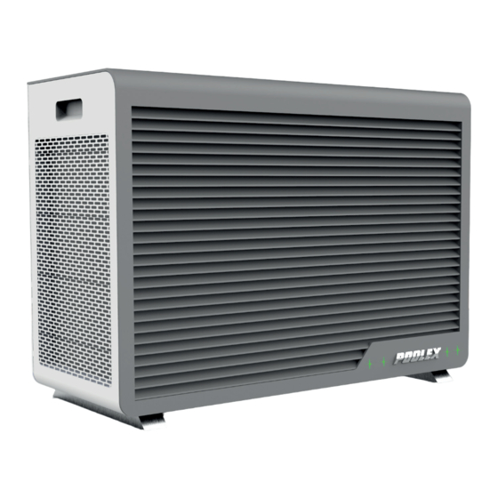
- Page 1 ARTICLINE FI INSTALLATION AND OPERATION MANUAL for your heat pump www.poolstar.fr...
- Page 2 Warning This heat pump contains R32 flammable refrigerant. Prior approval must be obtained before any procedure is performed on the refrigerant circuit. To ensure user safety, the following precautions must be followed before any procedure is per- formed on the refrigerant circuit. 1.
- Page 3 Acknowledgements Dear customer, Thank you for your purchase and your trust in our products. Our products are the result of years of research in the design and manufacture of heat pumps for pools. Our goal is to deliver high-quality products with exceptional performance. We took great care to put together this manual so you can get the most out of your Poolex heat pump...
- Page 4 PLEASE READ CAREFULLY These installation instructions form an integral part of the product. They must be provided to the installer and kept in a safe place by the user. If you lose this manual, please visit our website: www.poolex.fr The indications and warnings contained in this manual should be carefully read and understood as they provide important information regarding the safe handling and operation of the heat pump.
-
Page 5: Table Of Contents
Contents 1. General ..................................6 1.1 General terms and conditions of delivery ....................... 6 1.2 Safety instructions ..............................6 1.3 Water treatment ..............................7 2. Description ................................. 8 2.1 Package contents ..............................8 2.2 General characteristics ............................8 2.3 Technical characteristics ............................9 2.4 Product dimensions .............................. -
Page 6: General
1. General General terms and conditions of delivery All products and packaging, even those delivered carriage paid, travel at the risk of the recipient. Persons responsible for accepting delivery of the device must perform a visual inspection to make a note of any damage that may have occurred during transportation (refrigeration circuit, casing, electric box, frame). -
Page 7: Water Treatment
1. General When in use Do not touch the vent during operation due to the risk of serious injury. Do not leave the heat pump within reach of children due to the risk of injury caused by the heat exchanger fins. -
Page 8: Description
2. Description Package contents ✔ Poolex Articline Fi heat pump ✔ 2 hydraulic inlet/outlet connectors 1"1/2 threaded and union D50 ✔ Extension cable (10 m) for remote control panel ✔ This installation and operation manual ✔ Condensate discharge pipe ✔... -
Page 9: Technical Characteristics
2. Description Technical characteristics Poolex Articline Fi Testing conditions Heating capacity (kW) 20.01~3.95 26°C Consumption (kW) 3.38~0.286 Water 26°C 13.81~5.92 (Coeff. of performance) Heating capacity (kW) 15.53~2.95 15°C Consumption (kW) 3.12~0.439 Water 26°C 6.72~4.97 (Coeff. of performance) Heating capacity (kW) 6.95~2.35... -
Page 10: Product Dimensions
2. Description Product dimensions Dimensions in mm... -
Page 11: Exploded View
2. Description Exploded view 1. Base 15. Electrical elements 2. Front panel 1 16. Evaporator 3. Left panel 17. Titanium heat exchanger 4. Separation panel 18. EVI 5. Fan motor mount 19. Fan motor 6. Cover 20. Ventilator blades 7. Right side panel 21. -
Page 12: Installation
3. Installation WARNING: Installation must be performed by a qualified professional. This section is provided for information purposes only and must be checked and adapted if necessary according to the actual installation conditions. Prerequisite Equipment necessary for the installation of your heat pump: ✔... -
Page 13: Installation Diagram
3. Installation Installation diagram Heat pump Automatic treatment system 4-way valve (electrolyseur, dosing pump) Valve 1 Valve 5 Valve 3 Valve 2 Water outlet Water inlet Elevating studs Valve 4 Drain plug Condensation Filtration Circulation drainage pump FROM THE POOL TO THE POOL Valves 1, 2 and 3: Bypass valves Valves 4 and 5: Regulating valves... -
Page 14: Hydraulic Connection
3. Installation WARNING: Installation must be performed by a qualified professional. This section is provided for information purposes only and must be checked and adapted if necessary according to the actual installation conditions. Hydraulic connections By-Pass assembly Open valve Half-open valve The heat pump must be connected to the pool by means of a By-Pass assembly. - Page 15 3. Installation By-Pass assembly for one heat pump TO THE POOL Automatic treatment system POOL Filtration + Pump FROM THE POOL Caption Half-open valve Open valve By-Pass assembly for several heat pumps TO THE POOL Automatic treatment system POOL Filtration + Pump FROM THE POOL Caption Half-open valve...
-
Page 16: Electrical Installation
3. Installation WARNING: Installation must be performed by a qualified professional. This section is provided for information purposes only and must be checked and adapted if necessary according to the actual installation conditions. Electrical installation To function safely and maintain the integrity of your electrical system, the unit must be connected to a general electricity supply in accordance with the following regulations: •... -
Page 17: Electrical Connections
3. Installation Electrical connections WARNING: The heat pump’s power supply MUST be disconnected before any operation. Please comply with the following instructions to electrically connect the heat pump. Step 1: Dismount the electrical side panel with a screwdriver to access the electrical terminal block. Step 2: Insert the cable into the heat pump unit by passing it through the opening provided for that purpose. -
Page 18: Use
4. Use Wired remote control ROOM VALUE TEMP AUTO Before use, ensure that the filtration pump is working and that water is circulating through the heat pump. Before setting your set temperature, familiarise yourself with the different symbols represented by the remote control: Compressor Eco cooling mode... -
Page 19: Operating Modes
4. Use Operating modes Prior to setting your required temperature, you must first select an operating mode for your heat pump. The Articline proposes 7 operating modes combining: • Heating mode or cooling mode, • Eco or Boost or Silent modes. •... -
Page 20: Heat Pump Operating Mode Selector
4. Use Selecting the operating mode ROOM VALUE TEMP WARNING: Before starting, ensure that the filtration pump is operating correctly. AUTO Press on to switch operating mode. The different modes are displayed in the following order: Heating mode Cooling mode Heating mode Boost Cooling mode... -
Page 21: Clock Settings
4. Use ROOM VALUE TEMP ROOM VALUE ROOM VALUE ROOM VALUE Clock setting TEMP AUTO TEMP TEMP ROOM VALUE ROOM VALUE ROOM VALUE TEMP AUTO AUTO TEMP AUTO TEMP Step 1: Press for 5 seconds on to reach clock settings interface. Hours and minutes are flashing. ROOM VALUE TEMP... -
Page 22: On / Off Synchronization Adjustment
4. Use On / Off synchronization adjustment ROOM VALUE TEMP This function is used to program the start and stop time of your heat pump. You can program up to 2 different starts ROOM VALUE ROOM VALUE ROOM VALUE and stops. The setting is done as follows: TEMP TEMP AUTO... -
Page 23: Lock / Unlock
4. Use Locking / unlocking Without any action on your part for 60 s, the control box automatically locks up. icon appears. ROOM VALUE TEMP To unlock the screen: AUTO 1. Press any button. The screen lights up. 2. Press on for 5 s. -
Page 24: Status Values Control
4. Use ROOM VALUE ROOM VALUE ROOM VALUE TEMP TEMP TEMP 4.10 Status values control AUTO AUTO AUTO The system’s settings can be checked and adjusted via the remote control by following these steps. To access the verification settings, press on for 3s, then scroll downs the settings using the buttons. -
Page 25: User Parameters
4. Use ROOM VALUE TEMP 4.11 User settings ROOM VALUE ROOM VALUE AUTO TEMP TEMP AUTO AUTO Step 1: Press on for 3s to access the heat pump’s general settings. Step 2: Scroll down the main setting codes using the buttons. -
Page 26: Technical Parameters
4. Use 4.12 Technical settings WARNING: This operation is used to assist servicing and future repairs. ROOM VALUE The default settings should only be modified by an experienced professional person. ROOM VALUE TEMP TEMP VALUE Any change brought to reserved settings automatically cancels the warranty. ROOM TEMP AUTO... - Page 27 4. Use Default Code Description Variation values Reserved Reserved Reserved Reserved EEV maximum opening 50~480 480P EEV minimum opening 50~300 Reserved Forced refrigerant fluid recuperation OF / ON Reserved Maximum temperature setting in heating mode 35°C~60°C 40°C Minimum temperature setting in heating mode 15°C~25°C 15°C Maximum temperature setting in cooling mode...
-
Page 28: Operation
5. Operation Operation Use conditions For the heat pump to operate normally, the ambient air temperature must be between -25°C and 43°C. Advance notice Prior to starting the heat pump, please: ✔ Check that the equipment is secure and stable. ✔... -
Page 29: Using The Pressure Gauge
5. Operation Using the pressure gauge The gauge is for monitoring the pressure of the refrigerant contained in the heat pump. The values it indicates can vary considerably, depending on the climate, temperature and atmospheric pressure. When the heat pump is in operation: The gauge’s needle indicates the refrigerant pressure. -
Page 30: Maintenance And Servicing
6. Maintenance and servicing Maintenance and servicing WARNING: Before undertaking maintenance work on the unit, ensure that you have disconnected the electrical power supply. Cleaning The heat pump housing must be cleaned with a damp cloth. Using detergents or other household cleaning products may degrade the surface of the housing and affect its integrity. -
Page 31: Repairs
7. Repairs WARNING: Under normal conditions, a suitable heat pump can heat up the tub water by 1°C to 2°C per day. It is therefore normal that you do not feel any difference in temperature at the outlet level when the heat pump is on. A heated pool must be covered and insulated to avoid any heat loss. - Page 32 7. Repairs Code Faults Consequences Possible causes Actions 1. Beyond the working tempera- 1. Stop the equipment ture range Protection against The heat pump is not Er 13 2. Replace the sensor/move to the right ambient temperature running any more 2.
-
Page 33: Warranty
This warranty is void in the event of repairs to the device made by individuals which have not been authorised by Poolstar. The parts under warranty shall be replaced or repaired at the discretion of Poolstar. Faulty parts must be returned to us during the warranty period in order to be covered. The warranty does not cover unauthorized labor or replacement costs. -
Page 34: Appendices
9. Appendices Wiring diagram... - Page 35 NOTES – – – – – – – – – – – – – – – – – – – – – – – – – – – – – –...
- Page 36 TECHNICAL ASSISTANCE www.poolex.fr 06-2023 www.poolstar.fr...
Need help?
Do you have a question about the POOLEX ARTICLINE FI and is the answer not in the manual?
Questions and answers