Memmert ICO 50 Operating Manual
Co2 incubator
Hide thumbs
Also See for ICO 50:
- Addition to operating manual (24 pages) ,
- Operating manual (68 pages)
Table of Contents
Advertisement
Quick Links
Advertisement
Table of Contents

Subscribe to Our Youtube Channel
Related Manuals for Memmert ICO 50


Summary of Contents for Memmert ICO 50
- Page 1 OPERATING MANUAL INCUBATOR ICO MADE IN GERMANY. www.memmert.com...
- Page 2 Willi-Memmert-Str. 90-96 DE-91186 Büchenbach Germany Please contact our customer service before sending appliances for repair or before returning equipment, otherwise, we have to refuse acceptance of the shipment. © 2019 MEMMERT GmbH + Co. KG D33451 | Date 12/2019 Changes reserved...
- Page 3 Function and operation are identical. Other documents that have to be observed When operating the appliance with the MEMMERT AtmoCONTROL PC software, observe the separate software manual. To open the AtmoCONTROL software manual, click on “Help” in the AtmoCONTROL menu bar.
-
Page 4: Table Of Contents
Contents Contents For your safety Terms and signs used......................6 Product safety and dangers ....................6 Requirements of the operating personnel ................8 Responsibility of the owner ....................8 Intended use ........................8 Changes and conversions ....................9 Behaviour in case of malfunctions and irregularities ............9 What to do in case of accidents .................. - Page 5 Contents Malfunctions, warning and error messages Warning messages of the monitoring function ..............43 Malfunctions, operating problems and appliance errors ..........46 Power failure ........................47 Menu mode Overview ..........................48 Basic operation in menu mode using the example of language selection ....... 49 Setup..........................
-
Page 6: For Your Safety
For your safety For your safety 1.1 Terms and signs used In this manual and on the appliance itself, certain common terms and signs are used to warn you of possible dangers or to give you hints that are important in avoiding injury or damage. Observe and follow these notes and regulations to avoid accidents and damage. - Page 7 For your safety WARNING After removing covers, live parts may be exposed. You may receive an electric shock if you touch these parts. Disconnect the mains plug before removing any covers. Only electrical engineers may work on the electrical equipment of the appliances. WARNING When loading the appliance with an unsuitable load, poisonous or explosive vapours or gases may be produced.
-
Page 8: Requirements Of The Operating Personnel
For your safety and N are not dangerous substances in terms of the German Hazardous Substances Ordinance (GefStoffV). You should nevertheless familiarise yourself with the applicable safety regulations prior to handling such gas bottles. 1.3 Requirements of the operating personnel The appliance may only be operated and maintained by persons who are of legal age and have been instructed accordingly. -
Page 9: Changes And Conversions
For your safety 1.6 Changes and conversions No unauthorised changes or alterations may be made to the appliance. No parts may be added or inserted which have not been approved by the manufacturer. Unauthorised changes or alterations result in the CE declaration of conformity losing its valid- ity, and the appliance may no longer be operated. -
Page 10: Construction And Description
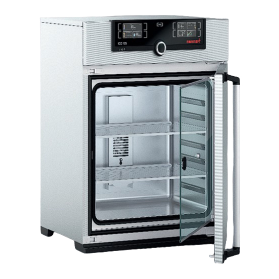
Construction and description Construction and description 2.1 Construction Fig. 2 Construction of CO incubators ICO 1 ControlCOCKPIT with capacitive function 4 Stainless steel perforated sheet keys and LCD displays (see page 27) 5 Water tray (passive humidity control) 2 On/Off switch (see page 23) 6 Adjustable feet 3 Inner glass door 7 Nameplate (see page 12) -
Page 11: Material
Construction and description 2.3 Material For the outer housing, MEMMERT uses stainless steel (Mat.No. 1.4016 – ASTM 430) and for the interior, stainless steel (Mat.No. 1.4301 – ASTM 304) is used, which stands out through its high stability, optimal hygienic properties and corrosion resistance to many (but not all!) chemical compounds (caution for example with chlorine compounds). -
Page 12: Designation (Nameplate)
Construction and description Ethernet interface Via Ethernet interface, the appliance can be connected to a network, so that you can trans- fer programmes created with the AtmoCON- TROL software to the appliance and read out protocols. The Ethernet interface is located on the rear of the appliance (Fig. -
Page 13: Technical Data
Construction and description 2.7 Technical data Appliance size Appliance width D* [mm] Appliance height E* [mm] 1066 1176 (varies due to adjustable feet) Appliance depth F* (without door handle) [mm] Depth of door handle [mm] Chamber width A* [mm] Chamber height B* [mm] Interior depth C* [mm] (less 35 mm for fan) Chamber volume [litres] Net weight [kg]... -
Page 14: Applied Directives And Standards
2.8 Applied directives and standards Based on the standards and guidelines listed in the following, the products described in this manual have received a CE label from the company Memmert: ► Directive 2004/108/EC amended (Directive of the council for harmonisation of the laws of the member states on electromagnetic compatibility). -
Page 15: Declaration Of Conformity
Construction and description 2.9 Declaration of conformity You can download the EC declaration of conformity of the appliance online: English: http://www.memmert.com/en/service/downloads/ce-statement/ German: http://www.memmert.com/de/service/downloads/eg-konformitaetserklaerung/ 2.10 Ambient conditions ► The appliance may only be used in enclosed areas and under the following ambient condi-... -
Page 16: Delivery, Transport And Setting Up
Delivery, transport and setting up Delivery, transport and setting up 3.1 For your safety WARNING Because of the heavy weight of the appliance, you could injure your- self if you try to lift it. To carry appliances of size 50, at least two persons are needed;... -
Page 17: Delivery
Delivery, transport and setting up 3.2 Delivery The appliance is packed in cardboard and is delivered on a wooden palette. 3.3 Transport The appliance can be transported in the following ways: ► With a forklift truck; move the forks of the truck entirely under the pallet. ►... -
Page 18: Setting Up
Delivery, transport and setting up 3.6 Setting up 3.6.1 Preconditions The installation site must be flat and horizontal and must be able to reliably bear the weight of the appliance (see Technical data on page 13). Do not place the appliance on a flamma- ble surface. - Page 19 Always attach the appliance to a wall with the tilt protection included in the delivery. In case there is not enough space, do not put the appliance into operation and do not open the door. Contact the Memmert service (see page 2). 1. Screw the tilt protection onto the back of the ap- pliance as illustrated.
- Page 20 Delivery, transport and setting up 3.6.3 Adjusting the doors For appliances it is possible to adjust doors that warp due to the floor conditions. In order to do so, every door has two adjuster screws at the top and at the bottom (Fig. 9). First, adjust the door at the top and then, if further adjustment is necessary, at the bottom as well.
-
Page 21: Putting Into Operation
4.2 Establishing water supply 4.2.1 Water specifi cations Only demineralised/deionised water with the following specifications may be used in Memmert appliances: ► Conductivity of 5 – 10 μS/cm ► pH value between 5 and 7 ►... -
Page 22: Co And N Connection
Putting into operation 4.2.2 For appliances with passive humidity control: inserting the water tray Mount the provided sealing lip to the narrow side of the water tray (Fig. 11) and fill 1.5 cm to 2 cm of water into the tray (for specifications see section 4.2.1). Place the water tray with the attached sealing lip in the centre of the appliance floor and carefully push it towards the rear panel until the sealing lip is completely under the ventilation opening, touching the rear panel along its entire length (Fig. -
Page 23: Switching On
Putting into operation CAUTION Danger of suffocation. CO and N can have a suffocating effect in high concentrations. In normal mode, the appliance emits small amounts of CO and N to its surroundings. You should therefore ensure that the room in which it is installed is properly ventilated. A ventilation rate of 250 m³... -
Page 24: Operation And Control
Operation and control Operation and control 5.1 For your safety WARNING Leaving the door open during operation can cause the appliance to overheat or pose a fi re hazard. Do not leave the door open during operation. WARNING Gas bottles may burst or explode at high temperatures. Keep the gas bottles away from open fl... -
Page 25: Opening The Door
Operation and control 5.3 Opening the door ► To open the door, pull the door handle to the side (to the left or to the right, depending on the door variation, see Fig. Fig. 15 , A). ► To close the appliance, push the door closed and push the door handle to the side (B). Fig. -
Page 26: Loading The Appliance
Operation and control 5.4 Loading the appliance WARNING When loading the appliance with an unsuitable load, poisonous or explosive vapours or gases may be produced. This could cause the appliance to explode, and people could be severely injured or poi- soned. - Page 27 Operation and control LIGHT LIGHT Fr 20.10.2010 20:31 12.Sept.2012 13:44 TEMP Manual Mode Holz trocknen aufheizen .4 °C 09:12h Set 37 .0 °C TIMER TIMER HUMIDITY ALARM of °C ALARM GRAPH °C 000°C .0 °C .0 °C auto 000°C auto off + / - 0.0 13:30 23.11.
- Page 28 Operation and control 5.5.2 Basic operation In general, all settings are made according to the following pattern: 1. Activate the desired parameter (e.g. tem- TEMP TEMP perature). To do so, press the correspond- .4 °C ing activation key on the left or right or °C .5°C the respective display.
- Page 29 Operation and control The status display shows you which operating mode or operating state the appliance is currently in. The current operating state is highlighted in colour and indicated by the text display: Appliance is in programme mode ■ 12.Sept.2012 13:44 Programme is stopped...
- Page 30 Operation and control Adjustment range: 0 to 20 % in steps of 0.1 % The number 1 or 2 displayed in the gas bottle symbol indicates which gas bottle is currently active. (only for corresponding model) Adjustment range: 1 % to 20 % in steps of 0.1 % 5.5.5 Operation with digital backwards counter with target time setting, adjustable from 1 minute to 99 days (timer) In timer operation, you can adjust the time the appliance runs at the set values.
- Page 31 Operation and control 4. Now, as described under 5.5.2 , set the individual values which you want the appliance to operate at. The set values can be changed at any time while the timer elapses. The changes are effective immediately. Setup , you can choose if the timer should run setpoint-dependent or not.
- Page 32 Operation and control Only the programme currently selected in menu mode and shown in the display can be used. If you want to process another programme, you need to activate it in menu mode first (description from page 60). 3. To start the programme, press the confir- 12.Sept.2012 10:44 mation key.
-
Page 33: Monitoring Function
Operation and control You can now ► restart the programme as described ► select another programme for processing in menu mode (see page 60) and run it as described. ► return to manual mode. To do so, reactivate it by pressing the 12.Sept.2012 13:44 activation key next to the status display, then turn the turn... - Page 34 Operation and control Emergency operation °C Setting MAX Set temperature Controller error Fig. 19 Schematic diagram of how TWW temperature monitoring works Electronic temperature limiter ( TWB) protection class 2 acc. to DIN 12 880 If the manually set monitoring temperature max is exceeded, the TWB switches off heating permanently (Fig.
- Page 35 Operation and control When the temperature violates the set tolerance band around the setpoint (in the example in Fig. 22: 50 °C ± 2 K) – e.g. if the door is opened during operation (section B of illustration) – the alarm is set off.
- Page 36 Operation and control 1. By turning the turn control, adjust the ALARM desired lower alarm limit value, in the example on the right 35.5 °C. °C °C The lower alarm limit value cannot be set auto higher than the top one. If no undertem- perature protection limit is required, set the lowest temperature.
- Page 37 Operation and control 7. With the turn control, adjust the desired ALARM tolerance band. We recommend 0.5 to 1 K. °C .5 °C auto 8. Press the confirmation key to confirm. ALARM Temperature monitoring is now active. .5 °C .5 °C auto 5.6.2 Humidity monitoring (only for appliances in the corresponding configuration)
- Page 38 Operation and control 3. Accept the selection by pressing the con- ALARM firmation key. The lower humidity alarm limit is automatically highlighted. .0 %rh 4. By turning the turn control, adjust the ALARM desired lower alarm limit, in the example on the right 50 % rh.
- Page 39 Operation and control 1. Press the activation key to the left of the ALARM display. The temperature moni- ALARM ALARM toring setting is automatically activated. 000°C °C .0 °C auto 000°C auto off 2. Turn the turn control until the CO adjust- ALARM ment entry is selected (upper gas bottle...
-
Page 40: Graph
Operation and control 5.6.4 O monitoring (only for appliances in the corresponding configuration) If O monitoring was triggered, this is Set 37.0 °C indicated by the O display: the actual value is highlighted in red and a warning symbol FEUCHTE FEUCHTE is shown ( Fig. -
Page 41: Sterilising The Appliance
Operation and control ► To change the time frame to °C 12.09.2012 Fr 20.10.2010 20: be displayed: Press the activa- tion key next to the ar- row symbols. The time frame to be displayed can now be 12 16 20 24 14.00 16.00 18.00... -
Page 42: Ending Operation
Operation and control 7. Turn the turn control until the hand 13.Sept.2012 17:44 symbol is highlighted. Manual mode Activate 8. Press the confirmation key to confirm. 12.Sept.2012 13:44 9. Replace the HEPA filter in the interior Manual Mode (optional). You can now load the appliance and con- tinue to operate it as usual. -
Page 43: Malfunctions, Warning And Error Messages
Do not try to rectify appli- ance errors yourself by opening the appliance, instead, contact the MEMMERT customer service department (see page 2) or an author- ised service point. 6.1 Warning messages of the monitoring function... - Page 44 Malfunctions, warning and error messages Description Cause Action Temperature alarm and The electronic Deactivate the alarm by pressing “TWB” are displayed temperature the confirmation key. limiter (TWB) TEMP Increase the difference between Page 35 permanently the monitoring and setpoint switched off °C temperature - by either increas- heating.
- Page 45 Malfunctions, warning and error messages 6.1.3 CO Monitoring Description Cause Action Alarm indicates that the Open the door for 30 sec. and upper CO alarm limit wait to see if the appliance then was exceeded steadily adjusts to the setpoint. If the error occurs again, contact customer service.
-
Page 46: Malfunctions, Operating Problems And Appliance Errors
Malfunctions, warning and error messages 6.2 Malfunctions, operating problems and appliance errors Description Cause Action Displays are dark External power supply Check the Page 21 was interrupted power supply Miniature fuse, appliance Contact customer Page 2 fuse or power module service faulty Displays cannot be... -
Page 47: Power Failure
Malfunctions, warning and error messages Description Cause Action ► Humidity sensor defective No humidity con- Error message trol possible the humidity display ► Contact customer Page 2 service HUMIDITY Set 50 .0 %rh ► sensor is defective No CO control Error message possible the CO... -
Page 48: Menu Mode
Menu mode Menu mode In menu mode, you can make basic settings, load programmes and export protocols, as well as calibrate the appliance. NOTICE ► Before changing menu settings, read the description of the respective functions on the fol- lowing pages to avoid possible damage to the appliance and/or chamber load. To enter menu mode, press the MENU key. -
Page 49: Basic Operation In Menu Mode Using The Example Of Language Selection
Menu mode 7.2 Basic operation in menu mode using the example of language selection In general, all settings in menu mode are done just like in operating mode: Activate the respective display, use the turn control for setting and press the confirmation key to accept the change. -
Page 50: Setup
Menu mode All other settings can be made accordingly. The settings possible are described in the follow- ing sections. If no new values are entered or confirmed for approx. 30 seconds, the appliance automati- cally restores the former values. 7.3 Setup 7.3.1 Overview SETUP In the... - Page 51 Menu mode SETUP 1. Activate the display. The entry Setup SETUP address is automatically highlighted. IP address 192. 168. 1 0 0 . 100 Balance Subnet mask 255. 255. 0 . 0 IP Adresse 192. 168. 1 0 0 . 100 Unit °C Einheit...
- Page 52 Menu mode 7.3.3 Timer Mode Here, you can choose whether the digital backwards counter with target time setting (see page 30, timer) should run IP address 255. 145. 1 3 6 . 225 setpoint-dependent or not – this determines whether the timer Subnet mask 255.
-
Page 53: Date And Time
Menu mode 7.4 Date and time TIME In the display, you can set the date and time, time zone and daylight saving time. Changes can only be made in manual operating mode. NOTICE Always set the time zone (and daylight saving time yes/no) before you set the date and time. Avoid changing the set time after that since this can lead to gaps or overlapping when record- ing measured values. -
Page 54: Calibration
Menu mode 7. Set daylight savings to off () or on ) with the turn control – in this case Date 12 . 05 . 2012 on ( ). Save the setting by pressing the Time 12 : 00 confirmation key. - Page 55 Menu mode Example: Temperature deviation at 42 °C should be corrected. 1. Press the activation key to the right of JUSTIEREN Calibrate CALIB display. The display is enlarged Temperatur Cal1 40.0 -0,2 Temperature 30.0 °C and the temperature adjustment option Cal1 Cal2 100.0...
- Page 56 Menu mode 9. In the SETUP, adjust the calibration value Cal2 to +1.6 K (measured reference value Cal1 minus displayed value) and save the set- 30.0 Cal2 ting by pressing the confirmation key. 40.0 Cal3 10. After the calibration procedure, the TEMP temperature measured by the reference instrument should now also be 42 °C.
- Page 57 Menu mode Example: Humidity deviation at 60 % should be corrected: 1. Press the activation key to the right of JUSTIEREN Calibrate CALIB display. The display is enlarged Temperatur Cal1 40.0 -0,2 Temperature 30.0 °C and the temperature adjustment option Cal1 Cal2 100.0...
- Page 58 Menu mode 9. Wait until the appliance reaches the set humidity and displays 60 % rh. The HUMIDITY reference instrument should display 58.5 % rh. .0 %rh 58.5 %rh Set 60 .0 %rh 10. In the SETUP, adjust the calibration value Cal2 to –1.5 % (measured reference value Temperature 40.0...
- Page 59 Menu mode 1. Press the activation key to the right of JUSTIEREN Calibrate CALIB display. The display is enlarged Temperatur Cal1 40.0 -0,2 Temperature 30.0 and the temperature adjustment option °C Cal1 Cal2 100.0 +0,1 40.0 Humidity °C Cal2 is automatically selected. Cal3 180.0 -0,2...
-
Page 60: Programme
Menu mode 9. Wait until the appliance reaches the setpoint and displays 10 %. The reference instrument displays 8.5 %, for example. 8.5 %CO2 10. In the SETUP, adjust the calibration value Cal2 to –1.5 % (reference value measured Temperature Cal1 %CO2 minus value displayed) and save the set-... -
Page 61: Sounds
Menu mode Select 2. Access the function by pressing the confirmation key. All programmes Select Test 012 Delete Test 022 available are displayed, including the Test 013 ones saved on the USB storage medium Test 014 (identified by the USB symbol ). -
Page 62: Protocol
Menu mode If you want to edit another list entry: Turn Sound the turn control until the respective entry if door open Keysound – e.g. (special configura- At the end tion) – is highlighted in colour. On alarm If door open 2. -
Page 63: User Id
Menu mode 2. Activate the protocol. To do so, press the activation key on the right side of the Protocol PROTOCOL display. The display is en- This Month larged and the period is au- control range tomatically highlighted. To select another logging period, use the turn control. - Page 64 Menu mode 7.9.2 USER ID activation and deactivation 1. Connect the USB storage medium with the USER ID data to the interface on the right side of the ControlCOCKPIT. 2. Activate the USER ID. To do so, press the USER-ID activation key on the right side of the Activate USER ID...
-
Page 65: Maintenance And Servicing
Maintenance and Servicing Maintenance and Servicing WARNING Danger due to electric shock. Disconnect the mains plug before any cleaning or maintenance work. 8.1 Regular maintenance Annually: ► Check the sterile filters and the water pump filters in the control unit and replace them if they are dirty. -
Page 66: Storage And Disposal
Storage and disposal Storage and disposal 9.1 Storage The appliance may only be stored under the following conditions: ► in a dry and enclosed, dust-free room ► frost-free ► disconnected from the power supply and gas supply Close the valves of the gas bottles and disconnect the hoses. Gas bottles may only be stored in closed rooms if these are sufficiently ventilated. - Page 67 Index Index Manufacturer 2 Material 11 Accessories 15 Electrical connection 11 Mechanical temperature Accidents 9 Electrical equipment 11 monitoring 34 Activation button 27 Electronic temperature moni- Menu 46 Alarm 32, 33, 35, 37, 38, 41 toring 32 Menu mode 46 Ambient conditions 15 Emergency 9 Minimum clearances 18...
- Page 68 Index Starting a programme 30 Timer 29 Sterile filter 63 Timer mode 50 Sterilisation programme 39 Transport 16, 17 Sterilisation programmes 8, Transport damage 17 58, 59 Turn control 27 Sterilising 39 TWW 32 Sterilizing the appliance 39 TWW temperature monitor- Storage after delivery 17 ing 33 Switching off 40...
- Page 72 Incubator ICO D33451 | Date 12/2019 englisch Memmert GmbH + Co. KG Postfach 1720 | D-91107 Schwabach Tel. +49 9122 925-0 | Fax +49 9122 14585 E-Mail: sales@memmert.com facebook.com/memmert.family...
Need help?
Do you have a question about the ICO 50 and is the answer not in the manual?
Questions and answers