Memmert ICHL Operating Manual
Climate chamber
Hide thumbs
Also See for ICHL:
- Quick start manual (56 pages) ,
- Quick start manual (40 pages) ,
- Quick start manual (52 pages)
Table of Contents
Advertisement
Quick Links
Advertisement
Table of Contents

Related Manuals for Memmert ICHL


Summary of Contents for Memmert ICHL
- Page 1 Operating manual ICHL ICHL eco Climate chamber ICHL ICHL eco www.memmert.com...
-
Page 2: Table Of Contents
Table of Contents Table of Contents 1. About this Manual 2. Safety 2.1 Terms and Symbols Used ............................2.1.1 Terms Used..............................2.1.2 Symbols Used .............................. 2.2 Product Safety and Dangers............................2.3 Safety Labels ................................2.4 Requirements to be met by Operating Personnel......................2.5 Responsibility of the Owner ............................ - Page 3 Table of Contents 5. Putting into Operation 5.1 Putting into Operation for the First Time........................22 5.2 Connecting the Unit to the Power Supply ........................22 5.3 Water specifications ..............................23 5.4 Connecting and Filling the Water Tank........................23 5.5 Switching on Unit ..............................23 6.
- Page 4 Table of Contents 8.3.3 Unit ................................46 8.3.4 Timer Mode ..............................46 8.3.5 Shelf Type (Grid or metal plate)........................46 8.3.6 Automatic Defrosting System (Defrost) ......................47 8.3.7 Dehumidification Interval ..........................47 8.3.8 Remote Control ............................48 8.3.9 Gateway............................... 48 8.4 Date and Time................................
-
Page 5: About This Manual
■ AtmoCONTROL software manual When operating the unit with the MEMMERT AtmoCONTROL PC software you will require the separate manual. You can find the manual for the AtmoCONTROL software in the AtmoCONTROL menu bar under 'Help' Retaining and passing on this manual This operating manual belongs to the unit and must always be kept in a location where it can be easily found by those working with the unit. - Page 6 E-mail: sales@memmert.com www.memmert.com International After Sales Memmert GmbH + Co. KG Willi-Memmert-Straße 90-96 | D-91186 Büchenbach | Germany Tel. +49 9171 9792 911 E-mail: service@memmert.com www.memmert.com If you have any queries, please always quote the product number on the nameplate.
-
Page 7: Safety
Safety Safety Terms and Symbols Used In this manual and on the unit itself, certain recurring terms and symbols are used to warn you of hazards or give you information that is important in order to prevent injury or damage. To avoid accidents and damage, observe and follow these instructions. These terms and symbols are explained below. -
Page 8: Product Safety And Dangers
Safety Product Safety and Dangers The units described in this manual are technically sophisticated, manufactured using high- quality materials and subject to many hours of testing in the factory. They reflect the state of the art and comply with recognised technical safety regulations. However, there are still risks involved, even when the units are used as intended. -
Page 9: Safety Labels
Climate chambers are designed to test the stability of pharmaceuticals, cosmetics, food etc. under long-term stable ambient conditions. Any other use may result in danger and damage. In case of doubt, please contact Memmert International After Sales. 2.6.2 Improper Use Any other use is improper and may result in danger and damage. -
Page 10: Changes And Alterations
Safety Changes and Alterations Unauthorised changes or alterations must not be made to the appliance. Parts that are not approved by the manufacturer must not be mounted or built in. Unauthorised changes or alterations result in the CE declaration of conformity losing its validity, and the appliance must no longer be operated. -
Page 11: Construction And Description
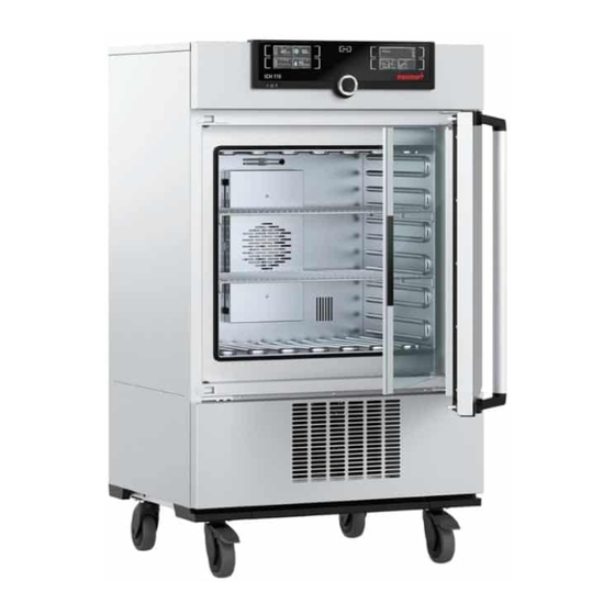
Construction and Description Construction and Description Design 1 ControlCOCKPIT with capacitive 2 Main switch function keys and LCD displays 3 Interior fan 4 Castors 5 Cooling unit 6 Nameplate 7 Inner glass door 8 Door handle 9 Power supply for the light cartridge 10 Light cartridge with fluorescent tubes (with bayonet connector) 11 Turn control with confirmation key... -
Page 12: Materials
Materials For the outer housing, MEMMERT processes stainless steel (Mat. No. 1.4016 – ASTM 430) for the chamber, stainless steel (Mat. No. 1.4301 – ASTM 304) is used, which stands out through its high stability, optimal hygienic properties and corrosion-resistance to many (but not all) chemical compounds (caution must be exercised with chlorine compounds, for example). -
Page 13: Nameplate
Construction and Description Ethernet interface You will find a description of how to transfer programs via Ethernet in the AtmoCONTROL software manual. The unit can be connected to a network via the Ethernet interface, so that you can transfer programmes created with the AtmoCONTROL software to the unit and export logs. For identification purposes, each unit connected must have its own unique IP address. -
Page 14: Technical Data
% rh 10 up to 80 Adjustment precision % rh Electrical data Power consumption ICHLeco 1450 1,450 1,550 230 V, 50 Hz Power consumption ICHL 1450 1,450 1,550 230 V, 50/60 Hz Power consumption ICHL 1,450 1,450 1,550 115 V, 50/60 Hz Max. current consumption ICHLeco 230 V, 50 Hz... -
Page 15: Applied Directives And Standards
We confirm that we always draw the attention of our suppliers to the legal restrictions on materials in accordance with our Company Standard for Material Compliance of Memmert GmbH + Co KG to ensure they take the original publications by the legislative authority into consideration at all times. -
Page 16: Ambient Conditions
Construction and Description 3.8.1.1 REACH information of Memmert GmbH + Co. KG acc. to Regulation (EG) No. 1907/2006, Art. 33 Based on current knowledge, we confirm that products or sub-products containing substances of very high concern (SVHC in the specified components) in the Candidate List with concentrations higher than 0.1 mass % are installed in the appliances we supply:... - Page 17 Construction and Description Optional accessories Ethernet to USB converter. Makes it possible to connect the Ethernet port of the appliance ■ to the USB port of a computer/laptop. ■ Reinforced grid with a load capacity of 60 kg (from appliance size 110). See also 2 Anti-tilt bracket [} 20] D53176...
-
Page 18: Delivery, Transport And Setting Up
Delivery, Transport and Setting Up Delivery, Transport and Setting Up Safety CAUTION Lifting the appliance incorrectly The appliance is heavy. The appliance is heavy, so you could injure yourself if you try to lift it on your own. – Make sure that a sufficient number of people are on hand to lift and carry the appliance. -
Page 19: Unpacking
– In case there is not enough space to fasten the appliance to a wall, do not put the appliance into operation and do not open the door. – Contact Memmert service. WARNING Risk of poisoning due to slow refrigerant leakage If the filling quantity of CO is greater than the maximum filling quantity (375 ... -
Page 20: Preconditions
Delivery, Transport and Setting Up 4.6.1 Preconditions ü The installation site must be flat and horizontal and must be able to reliably bear the weight of the unit (see }3.7 Technical Data). Place the unit on a heat-resistant, fireproof and non-flammable surface. -
Page 21: Adjusting The Doors
First, adjust the setting at the top of the door and, if this is not sufficient, adjust the bottom. A service video which explains how to adjust the door is available: www.memmert.com/de/downloads/media/service-videos/ 1. Open the door. 2. Loosen the screws. -
Page 22: Putting Into Operation
Putting into Operation Putting into Operation Putting into Operation for the First Time WARNING Condensation in the electrical components may cause short circuits. Due to temperature fluctuations during transport, condensation may form inside the unit. – After transporting or storing the unit in humid conditions, remove it from its packaging and allow it to acclimatise for at least 24 hours in normal ambient conditions. -
Page 23: Water Specifications
Putting into Operation Water specifications Only water with the following specifications may be used in Memmert units: Demineralised water and distilled water (a variety of terms are used commercially for this) ■ that is residue-free when it evaporates, according to regulation VDE 0510 and DIN 43530 ■... -
Page 24: Operation And Control
Operation and Control Operation and Control WARNING UV light can damage your eyes If you look directly at UV light and are not wearing protection, this could damage your eyes. – Always wear UV safety goggles when opening the door of the appliance. –... -
Page 25: Loading The Appliance
Operation and Control 1. To open the door, pull the door handle to the side. 2. To close the door, push the door closed and push the door handle to the side. Loading the Appliance WARNING Poisonous or explosive vapours and gases When loading the unit with an unsuitable load, poisonous or explosive vapours or gases may be produced. -
Page 26: Operating The Appliance
Operation and Control ■ Do not place any of the chamber load on the bottom, touching the side walls or right below the ceiling of the chamber. ■ See also the “correct loading” sticker on the appliance. The appliance is not suitable for long-term storage at sub-zero temperatures. During permanent operation, the glass door may ice over. -
Page 27: Basic Operation
Operation and Control 7 Main switch 8 Display of digital backwards counter with target time setting, adjustable from 1 minute to 99 days 9 Humidity control display 10 Humidity control activation key 11 Turn control for setpoint adjustment 12 Confirmation key (applies setting made with the turn control) 13 Activation key for adjusting the interior lighting (only for 14 Display of interior lighting (only for model ICH L / ICH L... -
Page 28: Manual Mode
Operation and Control }6.5.1 Manual Mode ■ Timer mode Operation with digital backwards counter with target time setting, adjustable from 1 minute to 99 days (Timer): The appliance runs at the values set until the set time has elapsed. }6.5.3 Digital Backwards Counter ■... -
Page 29: Interior Lighting
Operation and Control Temperature Heating operation is indicated by the symbol. Cooling is indicated by the symbol. You can display the temperature in °C or °F. }3.6 Nameplate Adjustment range depends on appliance (see }3.7 Technical Data). Humidity Setting range, see }3.7 Technical Data Humidification is indicated by the symbol. -
Page 30: Digital Backwards Counter
Operation and Control 3. Save the setting by pressing the confirmation key. ð The UV entry (UV light) is automatically activated. 4. By turning the turn control to the left or right, set the desired UV light value (0% = off, 100% = on). -
Page 31: Programme Mode
Operation and Control In Setup, you can choose if the timer should run setpoint-dependent or not, in other words, whether the timer should not start until a tolerance band around the setpoint temperature is reached or if it should start right after activation. The symbol on the timer display indicates that the timer is setpoint-dependent. - Page 32 Operation and Control Only the programme currently selected in the menu and shown in the display can be used. If you want to run another programme, you need to activate it in the menu first (description in }8 Menu Mode). 3. To start the programme, press the confirmation key. ð...
-
Page 33: Monitoring Function
Operation and Control You can now ■ restart the programme as described, select another programme to run in menu mode (see }8.6 Programme) and run it as ■ described, ■ return to manual mode. To do so, reactivate it by pressing the activation key next to the status display, then turn the turn control until the hand symbol is highlighted in colour and press the confirmation key. -
Page 34: Electronic Temperature Monitoring (Tww)
Operation and Control 6.6.2 Electronic Temperature Monitoring (TWW) The manually set min and max monitoring temperature of the electronic overtemperature protection is monitored by a temperature selector switch (TWW) protection class 3.3 acc. to DIN 12880. 6.6.3 Automatic Temperature Monitor (ASF) ASF is a monitoring device that automatically follows the set temperature setpoint within an adjustable tolerance band. -
Page 35: Adjusting The Temperature Monitoring
Operation and Control 6.6.5 Adjusting the Temperature Monitoring 1. Press the activation key to the left of the ALARM display. ð The temperature monitoring setting is automatically activated . 2. Confirm the selection by pressing the confirmation key. ð The min setting (undertemperature protection) is automatically activated. 3. -
Page 36: Humidity Monitoring
Operation and Control We recommend a tolerance band of 1 to 3 K. 10. Press the confirmation key to confirm. ð Temperature monitoring is now active. In menu mode you can set, whether an alarm should be accompanied by an acoustic }8.7 Acoustic signal (see Signals). -
Page 37: Graph
Operation and Control 6. By turning the turn control, set the required upper alarm limit, 70 % rh in the example on the left. 7. Press the confirmation key to confirm. 8. Press the activation key on the side to exit the Alarm display. ð... -
Page 38: Ending Operation
Operation and Control 3. Set the humidity with the turn control. 4. Press the confirmation key to confirm. ð The humidity profile is displayed. You can displace the display range and also zoom in/out as described in 6.7.1 Temperature Curve. See also 2 Temperature Curve [} 37] Ending Operation 1. -
Page 39: Malfunctions, Warning And Error Messages
– Follow the measures listed in the event of a malfunction. – Contact Memmert International After Sales. Do not try to rectify appliance errors yourself; instead you should contact Memmert International After Sales or an authorised customer service point. In case of enquiries, please always state the model and appliance number on the nameplate (see }3.6 Nameplate). -
Page 40: Humidity Monitoring
Malfunctions, Warning and Error Messages Description Cause Action The appliance does not heat any more Mechanical temperature limiter (TB) has Allow the appliance to cool down. ■ switched off the heating permanently. ■ Reset temperature limiter (TB). To do this, press the red button on the rear right of the appliance until you hear a click. -
Page 41: Power Failure
Malfunctions, Warning and Error Messages Error description Cause of errors Rectifying errors Appliance is in programme, timer or remote Wait for the programme or timer to end ■ control mode (“Write” or “Write + Alarm” or switch off the remote control mode). - Page 42 Malfunctions, Warning and Error Messages In timer or programme mode In case of an interruption of the power supply of less than 60 minutes, the current programme is continued from the point at which it was interrupted. For longer interruptions of the power supply, all appliance functions are switched off. After the power supply has been restored, the timer always starts again.
-
Page 43: Menu Mode
Menu Mode Menu Mode In menu mode, you can make basic settings, load programmes and export protocols, as well as adjust the appliance. Before changing the menu settings, read the description of the respective functions on the following pages to avoid possible damage to the appliance and/or chamber load. ▶... -
Page 44: Setup
Menu Mode If no new values are entered or confirmed for approx. 30 seconds, the appliance automatically restores the former values. Activate the desired setting (in this example the language): 1. To do so, press the activation key to the left or right of the respective display. ð... -
Page 45: Ip Address And Subnet Mask
Menu Mode }8.3.8 Remote ■ Remote control (see Control) ■ Gateway (see }8.3.9 Gateway) If the Setup menu contains more entries than can be displayed, this is indicated by the display “1/2”. This means that there is a second “page” of entries. To display the hidden entries, use the turn control to scroll beyond the lowest entry. -
Page 46: Unit
Menu Mode 4. Confirm the selection by pressing the confirmation key. ð The next three digits of the IP address are automatically marked. ð They can now also be set according to the description above. 5. After setting the last three digits, confirm the new IP address by pressing the confirmation key. -
Page 47: Automatic Defrosting System (Defrost)
Menu Mode 8.3.6 Automatic Defrosting System (Defrost) The integrated automatic defrosting system for the cooling unit ensures problem-free operation of the cooled incubator at low temperatures and in permanent operation. The defrosting interval can be set in 6-hour increments, between 6 and 48 hours. The Off setting deactivates automatic defrosting. -
Page 48: Remote Control
Menu Mode ■ For climate points in the low temperature range with low humidity, the interval should be extended If you change the dehumidification interval, test whether this has a positive effect on low ice formation in the chamber. 8.3.8 Remote Control Under the Remote control setup entry, you can set whether the appliance should be controlled via remote control and if so, in which mode. -
Page 49: Calibrate
Menu Mode 3. Confirm the selection by pressing the confirmation key. 4. Set the time zone of the installation site with the turn control (e.g. 00:00 for Great Britain, 01:00 for France, Spain or Germany). 5. Confirm the selection by pressing the confirmation key. 6. - Page 50 Menu Mode For temperature calibration, you will need a calibrated reference instrument. Example: Temperature deviation should be corrected 1. Press the activation key to the right of the CALIB display. ð The display is enlarged and the temperature adjustment option is automatically highlighted.
-
Page 51: Humidity Calibration
Menu Mode 10. Wait until the appliance reaches and displays the setpoint temperature. ■ The reference instrument will display the corresponding deviation. 11. In the SETUP, adjust the calibration correction value Cal2 to the deviation temperature (actual value measured minus setpoint value). 12. -
Page 52: Programme
Menu Mode 2. Turn the turn control until Humidity is highlighted. 3. Press the confirmation key repeatedly, until the calibration point Cal2 is highlighted. 4. With the turn control, set the calibration point Cal2 to 60% rh. 5. Save the setting by pressing the confirmation key. ð... -
Page 53: Acoustic Signals
Menu Mode 1. Insert the USB storage medium on the right side of the ControlCOCKPIT. ð You can now use one of the programmes saved on the USB storage medium. 2. Press the activation key on the left of the Prog display. ð... -
Page 54: Log
Menu Mode ■ in the event of an alarm ■ if the door is open 1. Press the activation key to the left of the SOUND display. ð The display is enlarged. ð The first category (in this case Keysound) is automatically highlighted. ð... -
Page 55: User Id
Menu Mode 1. Connect the USB storage medium to the port on the right of the ControlCOCKPIT. 2. Press the activation key on the right side of the Log display. ð The display is enlarged and the period This Month automatically highlighted. 3. -
Page 56: User Id Activation And Deactivation
Menu Mode 8.9.2 USER ID Activation and Deactivation 1. Insert the USB storage medium with the USER ID data into the USB port on the right of the ControlCOCKPIT. 2. Press the activation key on the right side of the USER-ID display. ð... -
Page 57: Maintenance And Servicing
Maintenance and Servicing Maintenance and Servicing DANGER Danger of suffocation inside the appliance If the appliances is a certain size, you can get accidentally locked in, which is potentially life-threatening. – Do not climb into the appliance. – Do not carry out cleaning work in the chamber alone. DANGER Live parts When covers are removed, live parts are exposed and contact with these parts may result... -
Page 58: Regular Maintenance
To guarantee perfect closed-loop control, we recommend calibrating the appliance once a year (see }8.5 Calibrate). See also 2 Calibrate [} 49] Repairs and Service Repairs and service work may only be carried out by specialist Memmert personnel and qualified service providers. D53176 02/2024... - Page 59 Maintenance and Servicing NOTICE Repairs and service work are described in a separate service manual. Replacing fluorescent tubes WARNING UV light can damage your eyes If you look directly at UV light and are not wearing protection, this could damage your eyes.
- Page 60 Maintenance and Servicing 8. Undo the screw connection of the glass cover all around. 9. Remove the glass cover and carefully put it aside. 10. Undo the corresponding screw connections on the holders of the fluorescent tubes. 11. Carefully pull the fluorescent tubes out of the holders. ð...
-
Page 61: Storage, Transport And Disposal
Storage, Transport and Disposal Storage, Transport and Disposal 10.1 Storage and Transport The appliance may only be stored and transported under the following conditions: ■ in a dry enclosed, dust-free room ■ disconnected from the power supply 10.2 Disposal This product is subject to Directive 2012/19/EC on Waste Electrical and Electronic Equipment (WEEE) of the European Parliament and EU Council of Ministers. - Page 62 Notes D53176 02/2024...
- Page 63 D53176 02/2024...
- Page 64 Operating manual Climate chamber ICHL ICHL eco D53176 Effective 02/2024 English...
Need help?
Do you have a question about the ICHL and is the answer not in the manual?
Questions and answers