Memmert ICH Series Operating Instructions Manual
Climate chamber
Hide thumbs
Also See for ICH Series:
- Operating instructions manual (64 pages) ,
- Operating instructions manual (68 pages)

Related Manuals for Memmert ICH Series


Summary of Contents for Memmert ICH Series
- Page 1 ICH L OPERATING INSTRUCTIONS CLIMATE CHAMBER ICH/ICH L 100% ATMOSAFE. MADE IN GERMANY. www.memmert.com | www.atmosafe.net...
- Page 2 Please contact our customer service before sending appliances for repair or before returning equipment, otherwise, we have to refuse acceptance of the shipment. © 2017 MEMMERT GmbH + Co. KG D33142 | Date 03/2017 We reserve the right to make changes...
- Page 3 Function and operation are identical. Other documents that have to be observed: ► For operation of the appliance with MEMMERT AtmoCONTROL, observe the separate software manual. To open the AtmoCONTROL software manual, click on “Help” in the AtmoCONTROL menu bar.
-
Page 4: Table Of Contents
Contents Contents For your Safety Terms and signs used......................6 Product safety and dangers ....................7 Safety labels ......................... 7 Requirements of the operating personnel ................8 Responsibility of the owner ....................8 Intended use ........................8 Changes and conversions ....................8 Behaviour in case of malfunctions and irregularities ............ - Page 5 Contents Malfunctions, warning and error messages Warning messages of the monitoring function ..............39 Malfunctions, operating problems and appliance errors ..........41 Power failure ........................42 Menu mode Overview ..........................43 Basic operation in menu mode using the example of language selection ....... 44 Setup..........................
-
Page 6: For Your Safety
For your Safety For your Safety 1.1 Terms and signs used In this manual and on the appliance itself, certain common terms and signs are used to warn you of possible dangers or to give you hints that are important in avoiding injury or damage. Observe and follow these hints and regulations to avoid accidents and damage. -
Page 7: Product Safety And Dangers
These stickers must not be removed and must always be well visible. If they become unrecognisable or if they Fig. 1 Warning sign on the door peel off, they must be replaced. They can be ordered from Memmert customer service. D33142 | Date 03/2017... -
Page 8: Requirements Of The Operating Personnel
Climate chambers ICH and ICHL are suitable for stability testing of pharmaceuticals, cosmetics, food etc under long-term stable ambient conditions. Any other use could be dangerous. In case of any doubts, please contact the Memmert customer service. The appliance is not explosion-proof (does not comply with the German workplace health &... -
Page 9: Behaviour In Case Of Malfunctions And Irregularities
For your Safety 1.8 Behaviour in case of malfunctions and irregularities The appliance may only be used in a flawless condition. If you as the operator notice irregu- larities, malfunctions or damage, immediately take the appliance out of service and inform your superior. -
Page 10: Construction And Description
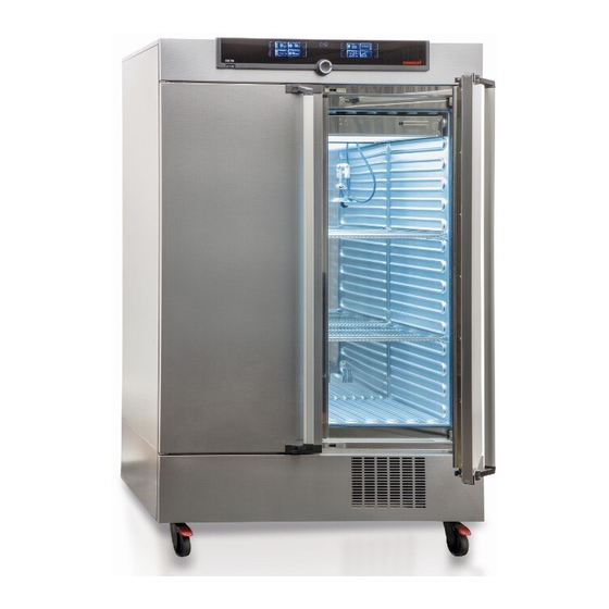
Construction and description Construction and description 2.1 Construction Fig. 3 Construction 1 ControlCOCKPIT with capacitive function 7 Nameplate (see page 13) keys and LCD displays (see page 26) 8 Inner glass door 2 On/Off switch (see page 23) 9 Illumination box with fluorescent tubes 3 Door handle (only for model ICHL, see page 60) 4 Chamber fan... -
Page 11: Construction And Function
The chamber load can be illuminated with UV light and/or daylight. 2.3 Material For the outer housing, MEMMERT uses stainless steel (Mat.No. 1.4016 – ASTM 430) and for the interior, stainless steel (Mat.No. 1.4301 – ASTM 304) is used, which stands out through its high stability, optimal hygienic properties and corrosion resistance to many (but not all!) chemical compounds (caution for example with chlorine compounds). - Page 12 Construction and description 2.5.2 Communication interfaces The communication interfaces are intended for appliances which meet the requirements of IEC 60950-1. USB interface The appliance is fitted by default with a USB interface in accordance with the USB specifica- tion. This way, you can ►...
-
Page 13: Designation (Nameplate)
Construction and description 2.6 Designation (nameplate) The nameplate (Fig. 6) provides information about the appliance model, manufacturer and technical data. It is attached to the front of the appliance, on the right behind the door (see page 10). Typ: ICH 260 F.-Nr.: Y613.0088 230 V ~ 5.9 A... -
Page 14: Technical Data
Construction and description 2.7 Technical data Appliance size Appliance width D* [mm] 1224 Appliance height E* [mm] 1233 1552 1950 Appliance depth F* (without door handle) [mm] Depth of door lock [mm] Chamber width A* [mm] 1040 Chamber height B* [mm] 1200 Chamber depth C* [mm] Chamber volume [litres]... -
Page 15: Applied Directives And Standards
2006 on machinery and amending directive 95/16/EC (revised)). Standards complied with: DIN EN ISO 12100-1:2003, DIN EN ISO 12100-2:2003 EN ISO 14121-1:2007, EN ISO 14121-2:2007 2.9 Declaration of conformity You can download the EC declaration of conformity of the appliance online: English: http://www.memmert.com/en/service/downloads/ce-statement/ German: http://www.memmert.com/de/service/downloads/eg-konformitaetserklaerung/ D33142 | Date 03/2017... -
Page 16: Ambient Conditions
Construction and description 2.10 Ambient conditions ► The appliance may only be used in enclosed areas and under the following ambient condi- tions: 15 °C to 28 °C (to 34 °C with limited temperature Ambient temperature and humidity range) Humidity rh max. -
Page 17: Delivery, Transport And Setting Up
Delivery, transport and setting up Delivery, transport and setting up 3.1 For your Safety Warning! Because of the heavy weight of the appliance, you could injure your- self if you try to lift it. For carrying appliances of size 110, at least 4 people are needed. -
Page 18: Delivery
Delivery, transport and setting up 3.2 Delivery The appliance is packed in cardboard and is delivered on a wooden palette. 3.3 Transport The appliance can be transported in three ways: ► With a forklift truck; move the forks of the truck entirely under the pallet. ►... -
Page 19: Setting Up
(see page 20). In case there is not enough space, do not put the appliance into operation and do not open the door. Contact the Memmert service (see page 2). The appliance may only be installed on the fl oor. - Page 20 Delivery, transport and setting up 3.6.2 Tilt protection Attach the appliance to a wall with the tilt protection. The tilt protection is included in the delivery. 1. Screw the tilt protection as shown onto the back of the appliance. 2. Bend the tilt protec- tion upwards by 90 °...
- Page 21 Delivery, transport and setting up 3.6.3 Adjusting the doors (only for model size 750) For model size 750, it is possible to adjust doors that warp due to the floor conditions. In order to do so, every door has two adjuster screws at the top and at the bottom (Fig. 10). First, adjust the door at the top and then, if further adjustment is necessary, at the bottom as well.
-
Page 22: Putting Into Operation
Putting into operation Putting into operation Caution: The first time the appliance is operated, it must not be left unattended until it has reached the steady state. The temperature limiter might have been triggered during transport. Press the red button on the back of the appliance to reset the temperature limiter before putting the appliance into operation. -
Page 23: Switching On
Putting into operation Fill the supplied water tank with water and connect it with the enclosed tube to the “H O” connection on the rear of the chamber (Fig. 12). For appliances of size 750, the tank can be attached to the appliance with the included tank holder (Fig. -
Page 24: Operation And Control
Operation and control Operation and control Warning! UV light is a danger to your eyes. Your eyes could be injured by UV light if you do not wear protection. Always wear UV safety goggles when opening the door of the ICHL climate chamber. -
Page 25: Loading The Appliance
Operation and control Warning! In case of appliances of a certain size, you can get accidentally locked in, which is life-threatening. Do not climb into the appliance! 5.3 Loading the appliance Warning! When loading the appliance with an unsuitable load, poisonous or explosive vapours or gases may be produced. - Page 26 Operation and control LIGHT Fr 20.10.2010 20:31 LIGHT LIGHT LIGHT LIGHT LIGHT 12.Sept.2012 13:44 TEMP Manual Mode Holz trocknen aufheizen .4 °C 09:12h Set 37 .0 °C TIMER TIMER HUMIDITY ALARM of °C ALARM GRAPH °C 000°C .5 °C .5 °C auto 000°C auto off...
- Page 27 Operation and control 3. Save the set value by pressing the confir- TEMP mation key. The display returns to normal and the .2 °C appliance begins adjusting to the defined set value. Set 37 .0 °C Additional parameters can be set accordingly. If no new values are entered or confirmed for approx.
- Page 28 Operation and control ► When the appliance is in remote control mode, the symbol appears in the temperature display: TEMP 5.4.4 Manual mode In this operating mode, the appliance runs in permanent .2 °C operation at the values set on the ControlCOCKPIT. Adjustment options Set 38 .0 °C...
- Page 29 Operation and control 2. By turning the turn control to the left or LIGHT right, set the desired daylight value (0 % = off, 100 % = on). 3. Save the setting by pressing the confir- LIGHT mation key. The UV entry ( UV light) is automatically activated.
- Page 30 Operation and control Up to a duration of 23 hours 59 minutes, the time is displayed in hh:mm (hours:minutes) format. For 24 hours and more, the format dd:hh (days:hours) is used. The maximum duration adjustable is 99 days 00 hours. 3.
- Page 31 Operation and control Starting a programme 1. Press the activation key to the right of Fr 20.10.2010 20:31 13.Sept.2012 17:44 the status display. The current operating manueller Betrieb Manual mode mode is highlighted automatically, in this Activate manual mode example GRAPH GRAPH ...
-
Page 32: Monitoring Function
Operation and control 3. Press the confirmation key to confirm. 12.Sept.2012 10:49 The programme is cancelled. A cancelled programme cannot be Test 012 resumed at the point it was cancelled. It must be restarted from the beginning. End of programme The display shows when the programme 12.Sept.2012... - Page 33 Operation and control If temperature monitoring has been triggered, this is indicated by the tempera- ture display: the actual temperature is TEMP TEMP TEMP highlighted in red and a warning °C °C °C TEMP symbol is shown ( Fig. 18 ). The type of °C °C Set 37.0...
- Page 34 Operation and control Automatic temperature monitor ( ASF) ASF is a monitoring device that automatically follows the set temperature setpoint within an adjustable tolerance band (Fig. 20). The ASF – if switched on – is automatically activated as soon as the actual temperature value reaches 50 % of the set tolerance band of the setpoint (in the example: 50 °C ±...
- Page 35 Operation and control 2. Save the selection by pressing the con- ALARM firmation key. The min setting (under- temperature protection) is automatically °C .0 °C activated. auto 3. By turning the turn control, adjust the ALARM desired lower alarm limit value, in the example on the right 35.5 °C.
- Page 36 Operation and control 10. Press the confirmation key to confirm. ALARM Temperature monitoring is now active. .5 °C .5 °C auto 5.5.2 Humidity monitoring If humidity monitoring has been triggered, Set 37.0 °C this is indicated by the humidity display: the actual humidity is highlighted in red FEUCHTE HUMIDITY...
-
Page 37: Graph
Operation and control 5. Accept the selection by pressing the con- ALARM firmation key. The upper humidity alarm limit is automatically highlighted. .0 %rh 6. By turning the turn control, adjust the ALARM desired upper alarm limit, in the example on the right 70 % rh. -
Page 38: Ending Operation
Operation and control 5.6.2 Humidity profi le 1. Activate graphic representa- °C 12.09.2012 Fr 20.10.2010 20 tion as described above and then press the activation key next to the parameter selec- tion. 12 16 20 24 14.00 16.00 18.00 2. Select humidity with the °C 12.09.2012... -
Page 39: Malfunctions, Warning And Error Messages
Ob- serve the separate service manual for this. Do not try to rectify appliance errors yourself but contact the MEMMERT customer service department (see page 2) or an authorised service point. In case of enquiries, please always specify the model and appliance number on the nameplate (see page 13). - Page 40 Malfunctions, warning and error messages Description Cause Action Appliance does not heat The mechanical 1. Wait until the appliance up any more temperature lim- cools down. iter (TB) perma- 2. Reset the TB. To do so, nently switched press the red button on off heating.
-
Page 41: Malfunctions, Operating Problems And Appliance Errors
Malfunctions, warning and error messages 6.2 Malfunctions, operating problems and appliance errors Error description Cause of errors Rectifying errors Displays are dark External power supply Check the page 22 was interrupted power supply Miniature fuse, appliance Contact customer page 2 fuse or power module service faulty... -
Page 42: Power Failure
Malfunctions, warning and error messages Error description Cause of errors Rectifying errors ► Error message E-6 in Humidity sensor defective No humidity con- the humidity display trol possible ► Contact customer page 2 service HUMIDITY Set 50 .0 %rh ► When switching on Cyan Contact customer... -
Page 43: Menu Mode
Menu mode Menu mode In menu mode, you can make basic settings, load programmes and export protocols, as well as adjust appliance parameters. Caution: Before changing menu settings, read the description of the respective functions on the fol- lowing pages to avoid possible damage to the appliance and/or chamber load. To enter menu mode, press the MENU key. -
Page 44: Basic Operation In Menu Mode Using The Example Of Language Selection
Menu mode 7.2 Basic operation in menu mode using the example of language selection In general, all settings in menu mode are done just like in manual mode: Activate the re- spective display, use the turn control for setting and press the confirmation key to accept the change. -
Page 45: Setup
Menu mode All other settings can be made accordingly. The settings possible are described in the follow- ing sections. If no new values are entered or confirmed for approx. 30 seconds, the appliance automati- cally returns to the main menu and restores the former values. 7.3 Setup 7.3.1 Overview SETUP... - Page 46 Menu mode SETUP 1. Activate the display. The entry SETUP SETUP address is automatically highlighted. IP address 192. 168. 1 0 0 . 100 Balance Subnet mask 255. 255. 0 . 0 IP Adresse 192. 168. 1 0 0 . 100 Unit °C Einheit...
- Page 47 Menu mode 7.3.4 Timer mode Here, you can choose whether the digital backwards counter with target time setting (see page 29) should run setpoint-depend- IP address 255. 145. 1 3 6 . 225 ent or not. This determines whether the timer should not start Subnet mask 255.
-
Page 48: Date And Time
Menu mode If humidity/room temperature are particularly high, it is possible that the factory setting for defrosting, 12 hours, is not sufficient. If this is the case, you should set a more frequent de- frosting interval, e.g. every 6 hours. Automatic defrosting is disabled with the setting . - Page 49 Menu mode Time zone 2. Turn the turn control until highlighted. Date 12 . 05 . 2012 Time 12 : 00 Time zone 01:00 Daylight savings 3. Accept the selection by pressing the confirmation key. Date 12 . 05 . 2012 Time 12 : 00 Time zone...
-
Page 50: Calibration
Menu mode 7.5 Calibration To guarantee perfect control, we recommend to calibrate the appliance once a year. 7.5.1 Temperature adjustment The appliances are temperature calibrated and adjusted at the factory. In case readjustment should be necessary later on – for example due to influence of the chamber load – the ap- pliance can be calibrated customer-specifically using three calibration temperatures of your choice: ►... - Page 51 Menu mode 3. With the turn control, set the calibration temperature Cal2 to 30 °C. Cal1 30.0 Cal2 37.0 Cal3 4. Save the setting by pressing the confir- mation key. The corresponding calibra- Cal1 tion value is automatically highlighted. 30.0 Cal2 37.0 Cal3...
- Page 52 Menu mode 7.5.2 Humidity calibration Humidity control can be adjusted according to customer requirements by means of three freely selectable balance points. For each selected calibration point, a positive or negative compensation correction value between –10 % and +10 % can be set (Fig. 28). For humidity adjustment, you will need a calibrated reference measuring device.
- Page 53 Menu mode JUSTIEREN 5. Save the setting by pressing the confir- mation key. The corresponding calibra- Temperature 10.0 Cal1 tion value is automatically highlighted. Humidity 60.0 Cal2 80.0 Cal3 6. Set the calibration value to 0.0 K and ac- cept the setting by pressing the confirma- Temperature 10.0 Cal1...
-
Page 54: Program
Menu mode 7.6 Program PROG In the display, programmes created using the AtmoCONTROL software can be trans- ferred to the appliance and saved on a USB storage medium. Here, programme to be used in manual mode can also be selected (see page 32) and programmes can be deleted. To load a programme from a USB stor- age medium: Connect the USB storage medium with the saved programme(s) -
Page 55: Sound
Menu mode 7.7 Sound Sound In the display, it can be define whether or not the appliance should emit acoustic signals and, if yes, on which events: ► on the press of a key ► at the end of a programme ►... -
Page 56: Protocol
Menu mode 7.8 Protocol The appliance continually logs all relevant measured values, settings and error messages at 1-minute intervals. The internal log memory is of the continuous memory type. The logging function cannot be switched off and is always active. The measured data are stored in the appliance, safe from manipulation. -
Page 57: User-Id
Menu mode 7.9 User-ID 7.9.1 Description With the User-ID function, you can lock the settings of individual (e.g. temperature) or all parameters, so that they cannot be changed at the appliance by accident or unauthorised persons. You can also lock setting options in menu mode (e.g. adjustment or date and time settings) this way. -
Page 58: Maintenance And Servicing
Maintenance and Servicing Maintenance and Servicing Warning! Danger due to electric shock. Before doing any maintenance work, pull out the mains plug. Warning! In case of appliances of a certain size, you can get accidentally locked in, which is life-threatening. Do not climb into the appliance! Caution! Danger of cuts due to sharp edges. - Page 59 Maintenance and Servicing 8.1.4 Cooling unit In order to guarantee perfect function and a long lifetime of the refrigeration unit, it is abso- lutely essential to remove dust deposits from the condenser (with a vacuum cleaner, paint- brush or bottle brush, depending on the amount of dust). To do so, open the screws at the lower front cover (number varies depending on the appliance size) and remove the front cover (Fig.
-
Page 60: Repairs And Service
Maintenance and Servicing 8.2 Repairs and Service Warning! After removing covers, live parts may be exposed. You may receive an electric shock if you touch these parts. Disconnect the mains plug before removing any covers. Any work inside the appliance may only be performed by qualifi ed electri- cians. - Page 61 Maintenance and Servicing 4. Turn the illumination box around and place it carefully on a smooth surface, so that the fluorescent tubes are on top (Fig. 34). Undo the four screws on the side. 5. Loosen the screws surrounding the glass plate. Remove the glass plate and put it aside. Fig.
- Page 62 Maintenance and Servicing 9. Push the illumination box back into the appliance. Guide the two connectors of the illumi- nation cooling into the feed-throughs at the rear of the appliance until they click in place (Fig. 36). Fig. 36 Put the illumination box back in 10.
-
Page 63: Storage And Disposal
Storage and disposal Storage and disposal 9.1 Storage The appliance may only be stored under the following conditions: ► in a dry and enclosed, dust-free room ► frost-free ► disconnected from the power supply Before storage, remove water tube and empty the water tank (see page 23). 9.2 Disposal This product is subject to the Directive 2002/96/EC on Waste Electrical and Electronic Equipment (WEEE) of the European Parliament... -
Page 64: Index
Index Index Accessories 16 Electrical connection 11 Maintenance 58 Activation key 26, 28 Electrical equipment 11 Malfunctions 9, 39, 41 Alarm 33, 34, 36, 39 Electronic temperature moni- Manufacturer 2 Ambient conditions 16 toring 33 Material 11 Ambient temperature 16 Emergency 9 Mechanical temperature Appliance error 41... - Page 65 Index Safety goggles 7, 24, 60 Tank holder 23 Unit 46 Safety labels 7 TB 34 Unpacking 18 Safety regulations 6, 10 Technical data 14 USB interface 12, 56 Service 60 Temperature 28 User ID 57 Servicing 60 Temperature adjustment 50 UV light 7, 24, 29, 60 Setting parameters 44 Temperature comparison 50...
- Page 68 Climate chamber ICH D33142 | Date 03/2017 englisch Memmert GmbH + Co. KG Willi-Memmert-Straße 90-96 | D-91186 Büchenbach Tel. +49 9122 925-0 | Fax +49 9122 14585 E-Mail: sales@memmert.com facebook.com/memmert.family Die Experten-Plattform: www.atmosafe.net...
Need help?
Do you have a question about the ICH Series and is the answer not in the manual?
Questions and answers