
Related Manuals for Memmert ICO105


Summary of Contents for Memmert ICO105
- Page 1 IVF module ADDITION TO OPERATING MANUAL INCUBATOR ICO WITH IVF MODULE ICO50 ICO105 MADE IN GERMANY. www.memmert.com...
- Page 2 91186 Büchenbach Germany Please contact our customer service department before sending appliances for repair or before returning equipment, or the shipment may be refused. © 2020 MEMMERT GmbH + Co. KG D39734 | Date 01/2020 Subject to change without notice...
- Page 3 Other documents to be observed: ► the operating manual for the ICO CO incubator ► For operation of the appliance with MEMMERT AtmoCONTROL, observe the separate software manual ► For service and repair work, observe the separate service manual Storage and resale This operating manual belongs with the appliance and should always be stored where per- sons working on the appliance have access to it.
-
Page 4: Table Of Contents
Contents Contents Safety regulations Terms and signs used......................5 1.1.1 Terms used ........................5 1.1.2 Signs used ......................... 5 Product safety and dangers ....................6 Intended use ........................7 Requirements of the operating personnel ................7 Responsibility of the operator ..................... 8 Changes and alterations ...................... -
Page 5: Safety Regulations
Safety regulations Safety regulations 1.1 Terms and signs used In this manual and on the appliance itself, certain common terms and signs are used to warn you of possible dangers or to give you hints that are important in avoiding injury or damage. Observe and follow these notes and regulations to avoid accidents and damage. -
Page 6: Product Safety And Dangers
Safety regulations 1.2 Product safety and dangers The appliances described in this manual are technically sophisticated, manufactured using high-quality materials and subject to many hours of testing in the factory. They reflect the state of the art and comply with recognised technical safety regulations. However, there are still risks involved, even when the appliances are used as intended. -
Page 7: Intended Use
Safety regulations CAUTION Danger of suffocation. CO and N in high concentrations can have a suffocating effect. In normal mode, the appliance emits small amounts of CO and N to its surroundings. You should therefore en- sure that the room in which it is installed is properly ventilated. You will need to extract 250 m³... -
Page 8: Responsibility Of The Operator
Safety regulations 1.5 Responsibility of the operator The operator of the incubator ► is responsible for the flawless condition of the incubator and for the incubator being oper- ated in accordance with its intended use; ► is responsible for ensuring that persons who are to operate or service the incubator are qualified to do this, have received instructions about the incubator and are familiar with this operating manual;... -
Page 9: Switching Off The Appliance In An Emergency
Safety regulations After inhaling CO High concentrations can cause suffocation. Symptoms may include a loss of mobility and unconsciousness. The victim is not aware of suffocating. Low concentrations of CO can cause accelerated breathing and headaches. Anyone affected should breathe fresh air, using a breathing device independent of recircu- lating air. -
Page 10: Design And Description
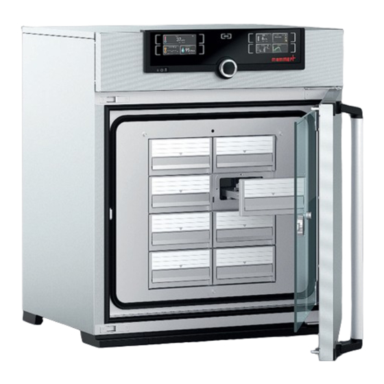
(IVF) application field. For this purpose, it is equipped with a slide-in unit - the IVF module - which in turn contains eight (ICO105) and six (ICO50) drawers, into which Petri dishes and 4-well plates as well as tube holders can be inserted on the included inserts. -
Page 11: Standard Package
When the door is opened, the temperature, humidity and CO control is interrupted until it closes again. 2.3 Standard package Standard package IVF module Drawer insert for Petri dishes ICO50: 12 units ICO105: 16 units 2 holders for IVF tubes Magnetic foil Custom calibration certificate D39734 | Date 01/2020... -
Page 12: Ivf-Module Installation
3.2.1 Cleaning The components for the installation frame are cleaned at the factory by Memmert. However, shipping and packaging may cause contamination. If necessary, clean the interior of the cabinet and the individual parts of the installation frame in advance. -
Page 13: Checking The Temperature Sensor
IVF-Module installation 3.2.2 Checking the temperature sensor Strong vibrations during transport could result in the temperature sensors being moved in their holders in the ceiling of the working chamber. Check whether the Temperature sensor is located correctly and if neces- sary, adjust in position in the holders (Fig. - Page 14 IVF-Module installation 2. Slide the side mounting frame on the left and right side over the heating bead- ing. The side installation frames rest on the lower installation frame. 3. Slightly tighten the side mounting frames on both sides with six M4 x 8 pan- head screws.
-
Page 15: Insert Ivf Module
IVF-Module installation 4. Place the upper mounting frame on the side mounting frame and slide it in carefully. The fixing screws Ⓐ must face forward. The upper frame rests on the side frame. 5. Tighten the upper mounting frame evenly on both sides with six M4 x 8 pan-head screws. -
Page 16: Removing The Drawers
IVF-Module installation 3.2.5 Removing the drawers The drawers can be removed for cleaning purposes and to remove the IVF module. 1. The drawers are secured by a locking mechanism. To pull out a drawer, lift the tab at the point marked with an arrow and pull out the drawer (Fig. 6). 2. -
Page 17: Remove Ivf Module
IVF-Module installation 3.2.6 Remove IVF module WARNING Risk of injury due to the weight of the IVF module. The IVF module 50 weighs approx. 25 kg, the IVF module 105 approx. 35 kg. Always hold the IVF module with both hands. 1. -
Page 18: Putting Into Operation
Putting into operation Putting into operation 4.1 Connecting the appliance Connect the appliance to the power, water and CO supply as described in the ICO operating manual. 4.2 Switching on the appliance Switch on the appliance as described in the ICO operating manual at the main switch. 4.3 Sterilising the appliance Before the appliance can be used, it has to be sterilised. - Page 19 Putting into operation 5. Close all drawers and the door. 6. Attach magnetic foil to the door (Fig. 12). 7. Carry out the sterilisation program as described in the ICO incubator's operating instructions. NOTICE Do not leave the appliance unattended during the sterilisation process.
-
Page 20: Operation
Operation Operation 5.1 Preparation Warm the device for 4 hours at 37 °C before incubating (without incubation material, but with inserted Petri dish holders and media holders as well as media). Do not activate the humidity control before the chamber has been heated for at least 4 hours. Depending on the use, set the rest of the parameters (CO and O ) (see ICO operating instructions). -
Page 21: Cleaning
Cleaning Cleaning WARNING Danger due to electric shock. Disconnect the mains plug before any cleaning or maintenance work. CAUTION Danger of cuts due to sharp edges. Always wear gloves when work- ing inside the chamber. Metal surfaces can be cleaned with normal stainless steel cleaning agents. To clean the cham- ber interior, the interior fittings have to be removed (instructions from page 15). - Page 24 ICO with IVF module D39734 | Date 01/2020 Englisch Memmert GmbH + Co. KG Postfach 1720 | D-91107 Schwabach Tel. +49 9122 925-0 | Fax +49 9122 14585 E-Mail: sales@memmert.com facebook.com/memmert.family...
Need help?
Do you have a question about the ICO105 and is the answer not in the manual?
Questions and answers