Memmert ICP Operating Manual
Compressor-cooled incubator
Hide thumbs
Also See for ICP:
- Quick start manual (56 pages) ,
- Quick start manual (40 pages) ,
- Quick start manual (52 pages)

Related Manuals for Memmert ICP


Summary of Contents for Memmert ICP
- Page 1 Operating manual ICPeco Compressor-cooled incubator ICP, ICPeco www.memmert.com...
-
Page 2: Table Of Contents
Table of Contents Table of Contents 1. About this Manual 2. Safety 2.1 Terms and Symbols Used ............................2.1.1 Terms Used..............................2.1.2 Symbols Used .............................. 2.2 Product Safety and Dangers............................2.3 Requirements to be met by Operating Personnel......................2.4 Responsibility of the Owner ............................2.5 Product Use ................................ - Page 3 Table of Contents 5.1 Putting into Operation for the First Time........................21 5.2 Connecting the Unit to the Power Supply ........................21 5.3 Switching on Unit ..............................21 6. Operation and Control 6.1 Operating Personnel..............................23 6.2 Opening the Door ..............................23 6.3 Loading the Appliance ..............................
- Page 4 Table of Contents 8.5 Calibrate.................................. 44 8.5.1 Temperature Calibration ..........................44 8.6 Programme................................45 8.7 Acoustic Signals ..............................46 8.8 Log..................................47 8.9 USER ID ................................... 48 8.9.1 Description ..............................48 8.9.2 USER ID Activation and Deactivation ......................49 9. Maintenance and Servicing 9.1 Cleaning ..................................
-
Page 5: About This Manual
Purpose and target audience This manual describes the design, function, transport, operation and maintenance of the product series Compressor-cooled incubators ICP. It is intended for use by trained personnel employed by the owner who are tasked with operating and/or maintaining the unit. - Page 6 E-mail: sales@memmert.com www.memmert.com International After Sales Memmert GmbH + Co. KG Willi-Memmert-Straße 90-96 | D-91186 Büchenbach | Germany Tel. +49 9171 9792 911 E-mail: service@memmert.com www.memmert.com If you have any queries, please always quote the product number on the nameplate.
-
Page 7: Safety
Safety Safety Terms and Symbols Used In this manual and on the unit itself, certain recurring terms and symbols are used to warn you of hazards or give you information that is important in order to prevent injury or damage. To avoid accidents and damage, observe and follow these instructions. These terms and symbols are explained below. -
Page 8: Requirements To Be Met By Operating Personnel
Safety DANGER Live parts When covers are removed, live parts are exposed and contact with these parts may result in electric shock. Electric shock can have serious health consequences including death. – Only authorised persons may carry out electrical installation work. –... -
Page 9: Product Use
Product Use 2.5.1 Intended Use Compressor-cooled incubators ICP must only be used for temperature testing of materials and substances in the context of the procedures and specifications described in this manual. 2.5.2 Improper Use Any other use is improper and may result in danger and damage. -
Page 10: Switching Off The Unit In An Emergency
Safety }7 Malfunctions, Warning and You can find information on troubleshooting in the chapter Error Messages. See also 2 Malfunctions, Warning and Error Messages [} 35] Switching off the Unit in an Emergency 1. Press the main switch on the unit. 2. Unplug the mains plug from the power source. ð... -
Page 11: Construction And Description
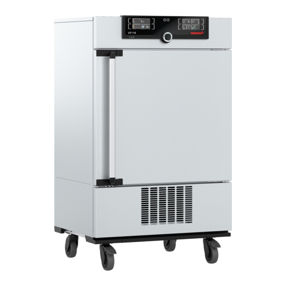
Construction and Description Construction and Description Design 1 ControlCOCKPIT with capacitive 2 Main switch function keys and LCD displays 3 Interior fan 4 Castors 5 Cooling unit 6 Nameplate 7 Inner glass door 8 Door handle 9 Turn control with confirmation key Description of Function The appliance can heat the chamber up to 60 °C and cool it down to -12 °C. -
Page 12: Materials
Construction and Description Materials For the outer housing, MEMMERT processes stainless steel (Mat. No. 1.4016 – ASTM 430) for the chamber, stainless steel (Mat. No. 1.4301 – ASTM 304) is used, which stands out through its high stability, optimal hygienic properties and corrosion-resistance to many (but not all) chemical compounds (caution must be exercised with chlorine compounds, for example). -
Page 13: Nameplate
Construction and Description The unit can be connected to a network via the Ethernet interface, so that you can transfer programmes created with the AtmoCONTROL software to the unit and export logs. For identification purposes, each unit connected must have its own unique IP address. A description of how to set the IP address is provided in chapter }8.3.2 ... -
Page 14: Technical Data
Construction and Description Technical Data Appliance size Stainless steel interior Volume Width 1,040 1,040 Height 1,200 Depth Max. number of shelves Max. loading per shelf Max. loading per appliance Max. loading per insertable/ removable drip tray Max. loading per bottom drip tray Patterned stainless Width 1,224... -
Page 15: Applied Directives And Standards
Construction and Description Applied Directives and Standards Based on the standards and guidelines listed below, the products described in this manual carry a CE mark from Memmert: ■ Directive 2014/30/EU with amendments (Council Directive on the approximation of the laws of the member states relating to electromagnetic compatibility). Standard complied with: DIN EN 61326-1:2012 ■... -
Page 16: Scope Of Delivery
Construction and Description 3.10 Scope of Delivery Standard delivery Mains connection cable ■ ■ Insertable/removable grid (load capacity 30 kg each) ■ USB storage medium with software and AtmoCONTROL manual ■ Operating manual Calibration certificate ■ ■ Separately packaged fastening material for wall mounting (see }4.6.2 Anti-tilt bracket). -
Page 17: Delivery, Transport And Setting Up
Delivery, Transport and Setting Up Delivery, Transport and Setting Up Safety CAUTION Lifting the appliance incorrectly The appliance is heavy. The appliance is heavy, so you could injure yourself if you try to lift it on your own. – Make sure that a sufficient number of people are on hand to lift and carry the appliance. -
Page 18: Unpacking
– In case there is not enough space to fasten the appliance to a wall, do not put the appliance into operation and do not open the door. – Contact Memmert service. WARNING Risk of poisoning due to slow refrigerant leakage If the filling quantity of CO is greater than the maximum filling quantity (375 ... -
Page 19: Preconditions
Delivery, Transport and Setting Up 4.6.1 Preconditions ü The installation site must be flat and horizontal and must be able to reliably bear the weight of the unit (see }3.7 Technical Data). Place the unit on a heat-resistant, fireproof and non-flammable surface. -
Page 20: Adjusting The Doors
First, adjust the setting at the top of the door and, if this is not sufficient, adjust the bottom. A service video which explains how to adjust the door is available: www.memmert.com/de/downloads/media/service-videos/ 1. Open the door. 2. Loosen the screws. -
Page 21: Putting Into Operation
Putting into Operation Putting into Operation Putting into Operation for the First Time WARNING Condensation in the electrical components may cause short circuits. Due to temperature fluctuations during transport, condensation may form inside the unit. – After transporting or storing the unit in humid conditions, remove it from its packaging and allow it to acclimatise for at least 24 hours in normal ambient conditions. - Page 22 Putting into Operation After the first start-up, the appliance display is set to English by default. You can change the language as described in chapter }8.2 Basic Operation in Menu Mode Using the Example of Language Selection. However, to get a basic overview of operating the appliance, you should read the following chapter first.
-
Page 23: Operation And Control
Operation and Control Operation and Control CAUTION Slip hazard Small amounts of condensed water may leak from the appliance when it is in operation. – Always wear shoes with non-slip soles and wipe up the condensed water immediately. CAUTION Injuries from cold surfaces The surfaces of the chamber and chamber load may be very cold. -
Page 24: Loading The Appliance
Operation and Control 2. To close the door, push the door closed and push the door handle to the side. Loading the Appliance WARNING Poisonous or explosive vapours and gases When loading the unit with an unsuitable load, poisonous or explosive vapours or gases may be produced. -
Page 25: Operating The Appliance
Operation and Control See also 2 Materials [} 12] 2 Technical Data [} 14] Operating the Appliance 6.4.1 ControlCOCKPIT In manual operation, the desired parameters are entered at the ControlCOCKPIT on the front of the appliance. You can also make basic settings here (menu mode). Warning messages are also displayed, e.g. -
Page 26: Basic Operation
Operation and Control 13 Activation key for adjustment of temperature 14 Monitoring display monitoring 15 Graphic representation 16 Activation key for graphic representation 6.4.2 Basic Operation In general, all settings are made as follows: Activate the desired parameter (e.g. temperature): 1. -
Page 27: Manual Mode
Operation and Control Programme Mode The appliance automatically runs programme sequences which have been defined using AtmoCONTROL software at a computer / laptop and then transferred to the appliance from a USB stick or via Ethernet. }6.5.3 Programme Mode ■ Remote control mode Via remote control ■... -
Page 28: Digital Backwards Counter
Operation and Control Fan speed Adjustment options: 10 to 100% in 10% increments See also 2 Basic Operation [} 26] 2 Nameplate [} 13] 2 Technical Data [} 14] 6.5.2 Digital Backwards Counter In timer mode, you can adjust the time the appliance runs at the set value. The appliance has to be in manual operating mode for this. -
Page 29: Programme Mode
Operation and Control Once the timer has elapsed, the display shows 00h:00m. ■ All functions are switched off. ■ In addition, an alarm sounds, and can be turned off by pressing the confirmation key. 5. To switch off the timer, press the activation key again to display the timer. 6. - Page 30 Operation and Control 3. To start the programme, press the confirmation key. ð The programme is executed. The display shows: ■ the programme name ■ the name of the first programme segment ■ the current cycle (in case of loops) You cannot change any parameters at the appliance while a programme is running.
-
Page 31: Monitoring Function
Operation and Control 2 Menu Mode [} 38] 2 Programme [} 45] Monitoring Function 6.6.1 Temperature Monitoring The appliance is equipped with multiple overtemperature protection in accordance with DIN 12880. This is designed to prevent damage to the chamber load and/or appliance in case of a malfunction: electronic temperature monitoring (TWW) ■... -
Page 32: Automatic Temperature Monitor (Asf)
Operation and Control 6.6.3 Automatic Temperature Monitor (ASF) ASF is a monitoring device that automatically follows the set temperature setpoint within an adjustable tolerance band. The ASF – if switched on – is automatically activated as soon as the actual temperature value reaches 50% of the set tolerance band of the setpoint for the first time (section A). - Page 33 Operation and Control 2. By turning the turn control, adjust the desired lower alarm limit. The lower alarm limit cannot be higher than the upper alarm limit. If no undertemperature protection is required, set the lowest temperature. 3. Press the confirmation key to confirm. ð...
-
Page 34: Graph
Operation and Control See also 2 Acoustic Signals [} 46] Graph The GRAPH display provides an overview of the chronological sequence of the set values and the actual values as a curve. ■ Press the activation key again to close the graphic display. 6.7.1 Temperature Curve 1. -
Page 35: Malfunctions, Warning And Error Messages
– Follow the measures listed in the event of a malfunction. – Contact Memmert International After Sales. Do not try to rectify appliance errors yourself; instead you should contact Memmert International After Sales or an authorised customer service point. In case of enquiries, please always state the model and appliance number on the nameplate (see }3.6 Nameplate). -
Page 36: Malfunctions, Operating Problems And Unit Errors
Malfunctions, Warning and Error Messages Description Cause Action The appliance does not heat any more Mechanical temperature limiter (TB) has Allow the appliance to cool down. ■ switched off the heating permanently. ■ Reset temperature limiter (TB). To do this, press the red button on the rear right of the appliance until you hear a click. -
Page 37: Power Failure
Malfunctions, Warning and Error Messages Error description Cause of errors Rectifying errors Error message E-3 in the temperature Working and monitoring sensor faulty. Switch off appliance ■ display ■ Remove load ■ Notify customer service Start animation after switching on appears Cyan Notify customer service ■... -
Page 38: Menu Mode
Menu Mode Menu Mode In menu mode, you can make basic settings, load programmes and export protocols, as well as adjust the appliance. Before changing the menu settings, read the description of the respective functions on the following pages to avoid possible damage to the appliance and/or chamber load. ▶... -
Page 39: Setup
Menu Mode If no new values are entered or confirmed for approx. 30 seconds, the appliance automatically restores the former values. Activate the desired setting (in this example the language): 1. To do so, press the activation key to the left or right of the respective display. ð... -
Page 40: Ip Address And Subnet Mask
Menu Mode Gateway (see }8.3.8 Gateway) ■ If the Setup menu contains more entries than can be displayed, this is indicated by the display “1/2”. This means that there is a second “page” of entries. To display the hidden entries, use the turn control to scroll beyond the lowest entry. The page display then changes to “2/2”. -
Page 41: Unit
Menu Mode 4. Confirm the selection by pressing the confirmation key. ð The next three digits of the IP address are automatically marked. ð They can now also be set according to the description above. 5. After setting the last three digits, confirm the new IP address by pressing the confirmation key. -
Page 42: Automatic Defrosting System (Defrost)
Menu Mode 8.3.6 Automatic Defrosting System (Defrost) The integrated automatic defrosting system for the cooling unit ensures problem-free operation of the cooled incubator at low temperatures and in permanent operation. The defrosting interval can be set in 6-hour increments, between 6 and 48 hours. The Off setting deactivates automatic defrosting. -
Page 43: Date And Time
Menu Mode Date and Time In the TIME display, you can set date and time, time zone and summer time. Changes can only be made in manual operating mode. Always set the time zone (and summer time yes/no) before you set the date and time. Avoid changing the set time after that since this can lead to gaps or overlapping when recording measured values. -
Page 44: Calibrate
Menu Mode Calibrate NOTICE To guarantee problem-free closed-loop control, we recommend calibrating the appliance once a year. 8.5.1 Temperature Calibration The appliances are temperature calibrated and adjusted at the factory. If readjustment is necessary – for example due to the influence of the chamber load – the appliance can be calibrated for the specific customer using three possible calibration temperatures: ■... -
Page 45: Programme
Menu Mode 4. Save the setting by pressing the confirmation key. ð The corresponding calibration correction value is automatically highlighted. 5. Set the calibration correction value to 0.0 K. 6. Save the setting by pressing the confirmation key. 7. Position the sensor of a calibrated reference instrument centrally in the working chamber of the appliance. -
Page 46: Acoustic Signals
Menu Mode 2. Press the activation key on the left of the Prog display. ð The display is enlarged and the Select entry is automatically highlighted. ð The programmes available for activation are shown on the right. ð The programme currently available for use – in this example Test 012 – is highlighted in orange. -
Page 47: Log
Menu Mode 1. Press the activation key to the left of the SOUND display. ð The display is enlarged. ð The first category (in this case Keysound) is automatically highlighted. ð The current settings are shown on the right. If you want to edit another list entry: ■... -
Page 48: User Id
Menu Mode 1. Connect the USB storage medium to the port on the right of the ControlCOCKPIT. 2. Press the activation key on the right side of the Log display. ð The display is enlarged and the period This Month automatically highlighted. 3. -
Page 49: User Id Activation And Deactivation
Menu Mode 8.9.2 USER ID Activation and Deactivation 1. Insert the USB storage medium with the USER ID data into the USB port on the right of the ControlCOCKPIT. 2. Press the activation key on the right side of the USER-ID display. ð... -
Page 50: Maintenance And Servicing
Maintenance and Servicing Maintenance and Servicing DANGER Danger of suffocation inside the appliance If the appliances is a certain size, you can get accidentally locked in, which is potentially life-threatening. – Do not climb into the appliance. – Do not carry out cleaning work in the chamber alone. DANGER Live parts When covers are removed, live parts are exposed and contact with these parts may result... -
Page 51: Regular Maintenance
(see }8.5 Calibrate). See also 2 Calibrate [} 44] Repairs and Service Repairs and service work may only be carried out by specialist Memmert personnel and qualified service providers. NOTICE Repairs and service work are described in a separate service manual. -
Page 52: Storage And Disposal
Storage and Disposal Storage and Disposal 10.1 Storage The unit may only be stored under the following conditions: ■ in a dry enclosed, dust-free room ■ disconnected from the power supply 10.2 Disposal This product is subject to Directive 2012/19/EC on Waste Electrical and Electronic Equipment (WEEE) of the European Parliament and EU Council of Ministers. - Page 53 Notes D30374 11/2023...
- Page 54 D30374 11/2023...
- Page 55 D30374 11/2023...
- Page 56 Operating manual Compressor-cooled incubator ICP, D30374 Effective 11/2023 ICPeco English...
Need help?
Do you have a question about the ICP and is the answer not in the manual?
Questions and answers