
Subscribe to Our Youtube Channel
Related Manuals for Pfeiffer Vacuum MVP 030-3 C DC


Summary of Contents for Pfeiffer Vacuum MVP 030-3 C DC
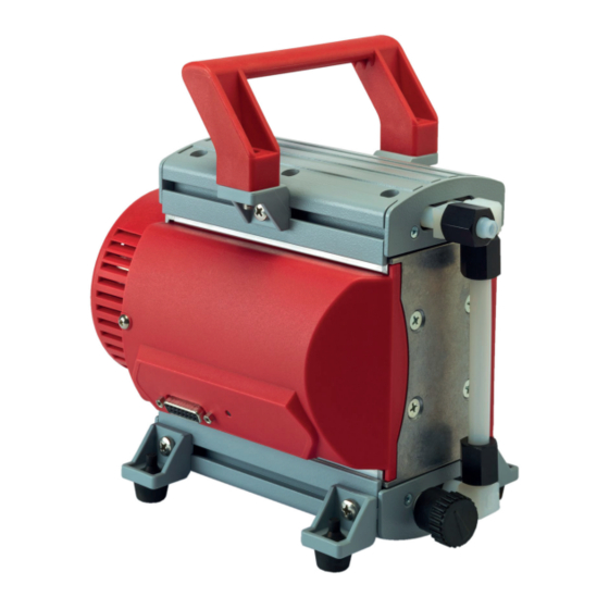
- Page 1 OPERATING INSTRUCTIONS Translation of the Original MVP 030-3 C DC Diaphragm pump for corrosive gases...
-
Page 2: Telegram Example
Dear Customer, Thank you for choosing a Pfeiffer Vacuum product. Your new diaphragm pump is designed to support you with its performance, perfect operation and without impacting your individual application. The name Pfeiffer Vacuum stands for high-quality vacuum technology, a comprehensive and complete range of top-quality products and first-class service. -
Page 3: Table Of Contents
Limits of use of the product Proper use Foreseeable improper use Personnel qualification 2.7.1 Ensuring personnel qualification 2.7.2 Personnel qualification for maintenance and repair 2.7.3 Advanced training with Pfeiffer Vacuum Product description Function Identifying the product Scope of delivery Transportation and Storage... - Page 4 Table of contents Operation Putting the vacuum pump into operation Switching on the vacuum pump Configuring the connections with the Pfeiffer Vacuum parameter set 8.3.1 Configuring the digital outputs 8.3.2 Selecting the interfaces Operating modes 8.4.1 Speed actuator operation 8.4.2 Standby mode 8.4.3 Normal operation...
- Page 5 Tbl. 22: Spare parts packs Tbl. 23: Accessories Tbl. 24: Conversion table: Pressure units Tbl. 25: Conversion table: Units for gas throughput Tbl. 26: Technical data MVP 030-3 C DC Tbl. 27: Materials that make contact with the process media 5/56...
- Page 6 Connection options via interface RS-485 Fig. 9: Gas ballast valve Fig. 10: Handle Fig. 11: Pump head and valves Fig. 12: Replacing the diaphragms Fig. 13: Correct mounting orientation of the valves in the head cover Fig. 14: Dimensions MVP 030-3 C DC 6/56...
-
Page 7: About This Manual
Keep the manual for future consultation. 1.1 Validity This operating instructions is a customer document of Pfeiffer Vacuum. The operating instructions de- scribe the functions of the named product and provide the most important information for the safe use of the device. The description is written in accordance with the valid directives. The information in this op- erating instructions refers to the product's current development status. -
Page 8: Stickers On The Product
About this manual Note 1.3.3 Stickers on the product This section describes all the stickers on the product along with their meaning. Rating plate Pfeiffer Vacuum D - 35614 Asslar Rating plate of the diaphragm pump Germany S(N ) 2 1.8 m /h Mod. -
Page 9: Abbreviations
About this manual 1.3.4 Abbreviations Abbreviation Meaning in this document Operating instructions C version Corrosive gas version Direct current Display and Control Unit Nominal diameter (diamètre nominal) ETFE Ethylene tetrafluoroethylene copolymer Rotation speed value of a vacuum pump (frequency, in rpm or Hz) FFKM Perfluoroelastomer Fluoropolymer rubber... -
Page 10: Safety
Safety 2 Safety 2.1 General safety information The following 4 risk levels and 1 information level are taken into account in this document. DANGER Immediately pending danger Indicates an immediately pending danger that will result in death or serious injury if not observed. ►... - Page 11 Safety CAUTION Danger of injury from bursting as a result of high pressure in the exhaust line Faulty or inadequate exhaust pipes lead to dangerous situations, e.g. increased exhaust pressure. There is a danger of bursting. Injuries caused by flying fragments, the escaping of high pressure, and damage to the unit cannot be excluded.
-
Page 12: Safety Precautions
Safety Risks during maintenance, decommissioning and in event of malfunctions WARNING Health hazard through poisoning from toxic contaminated components or devices Toxic process media result in contamination of devices or parts of them. During maintenance work, there is a risk to health from contact with these poisonous substances. Illegal disposal of toxic sub- stances causes environmental damage. -
Page 13: Limits Of Use Of The Product
Safety Duty to provide information on potential dangers The product holder or user is obliged to make all operating personnel aware of dangers posed by this product. Every person who is involved in the installation, operation or maintenance of the product must read, understand and adhere to the safety-related parts of this document. -
Page 14: Proper Use
► Use the vacuum pump for vacuum generation only. ► Adhere to the installation, commissioning, operating, and maintenance instructions. ► Do not use any accessory parts other than those recommended by Pfeiffer Vacuum. 2.6 Foreseeable improper use Improper use of the product invalidates all warranty and liability claims. Any use that is counter to the purpose of the product, whether intentional or unintentional, is regarded as improper use;... -
Page 15: Personnel Qualification For Maintenance And Repair
─ Customer with Pfeiffer Vacuum service training ─ Pfeiffer Vacuum service technician 2.7.3 Advanced training with Pfeiffer Vacuum For optimal and trouble-free use of this product, Pfeiffer Vacuum offers a comprehensive range of courses and technical trainings. For more information, please contact Pfeiffer Vacuum technical training. -
Page 16: Product Description
3 Product description 3.1 Function The diaphragm pump of the MVP 030-3 C DC series is a dry compressing vacuum pump with 3 pump- ing stages. The vacuum pump is a positive displacement pump with a periodic change in suction cham- ber size, produced by the movement of the diaphragm. The gas flow causes the valves to open and close automatically. -
Page 17: Transportation And Storage
6. Always place the vacuum pump on an adequately sized, level surface. 4.2 Storing the vacuum pump Storage Pfeiffer Vacuum recommends storing the products in their original transport packaging. Procedure 1. Seal the vacuum connection with the blind plug. 2. Make sure that the gas ballast valve is closed. -
Page 18: Installation
NOTICE Property damage from contaminated gases Pumping gases that contain contamination damages the vacuum pump. ► Use suitable filters or separators from the Pfeiffer Vacuum range of accessories, to protect the vacuum pump. Installation and operation of accessories Pfeiffer Vacuum offers a series of special, compatible accessories for its diaphragm pumps. -
Page 19: Connecting The Exhaust Side
Installation 4. Depending on the pump type, use PVC or metallic hoses with flange connections from the Pfeiff- er Vacuum component shop. 5. Connect the vacuum pump to the vacuum system using the vacuum connection. 5.3 Connecting the exhaust side CAUTION Danger of injury from bursting as a result of high pressure in the exhaust line Faulty or inadequate exhaust pipes lead to dangerous situations, e.g. -
Page 20: Interfaces
Interfaces 6 Interfaces NOTICE Property damage on the electronics Separating all plug-and-socket connections within the bus system with voltage supply switched on may lead to the destruction of electronic components. ► Always disconnect the voltage supply before removing the connecting plug. ►... - Page 21 Interfaces Fig. 5: Connection example: MVP 030-3 DC – DCU/TPS 1 TPS 2 DCU/HPU Connecting cable, order number: PM 061 350 -T 21/56...
-
Page 22: Voltage Supply
Connecting cable, order number: PE 100 013 -T 3 MVP 6.1 Voltage supply 24 V DC input: The voltage supply is carried out using a connecting cable from the Pfeiffer Vacuum accessories or using a cable provided by the customer. ● Pin 1: +24 V DC ●... -
Page 23: Outputs
6.3 Outputs The digital outputs have a maximum load limit of 24 V/50 mA per output. All outputs listed are configura- ble with the Pfeiffer Vacuum parameter set via the RS-485 interface (description relates to factory set- tings). DO1/Pin 8... -
Page 24: Cross-Linked Via The Rs-485 Connection
Interfaces Networking as RS-485 bus The group address of the electronic drive unit is 902. 1. Install the devices according to the specification for RS-485 interfaces. 2. Make sure that all devices connected to the bus have different RS-485 device addresses [P:797]. 3. -
Page 25: Connection Options Via Interface Rs-485
2. Use the option to connect a PC via the USB/RS-485 converter. 6.7 Pfeiffer Vacuum protocol for RS-485 interface 6.7.1 Telegram frame The telegram frame of the Pfeiffer Vacuum protocol contains only ASCII code characters [32; 127], the exception being the end character of the telegram C . Basically, a master (e.g. -
Page 26: Telegram Description
Interfaces 6.7.2 Telegram description Data query --> Control command --> Data response / Control command understood --> Error message --> NO_DEF Parameter number n2–n0 no longer exists _RANGE Data dn–d0 outside the permissible range _LOGIC Logical access error 6.7.3 Telegram example 1 Data query Current rotation speed (parameter [P:309], device address slave: "123") -->... - Page 27 Interfaces Data type Description Length Example l1 – l0 u_real Positive fixed point number 001571 corresponds with 15.71 u_expo Positive exponential number 1.2E-2 is equivalent to 1,2 · 10 005E8 is equivalent to 5 · 10 string Any character string with 6 charac- TC_110, TM_700 ters.
-
Page 28: Parameter Set
All variables of the vacuum pump relevant for the function are stored as parameters in the electronic drive unit. Each parameter has a three-digit number and a description. Parameters can be used via Pfeiffer Vacuum display and control panels or via RS-485 with the Pfeiffer Vacuum protocol. Conventions Parameters are printed in bold as three-digit numbers in square brackets. -
Page 29: Status Requests
Parameter set Display Designations Functions Data Unit min. max. type cess fault type stored SpdSet- Speed actua- 0 = off Mode tor operation 1 = on CtrlViaInt Operation of 1 = remote the interface 2 = RS-485 4 = PV.can 32 = Keys on the front panel 255 = Interface selection... -
Page 30: Reference Value Inputs
The basic parameter set is set in the electronic drive unit ex-factory. For controlling con- nected external components (e.g. vacuum measuring instruments), additional parameters (extended parameter set) are available in the corresponding Pfeiffer Vacuum display and control panels. ● Refer to the corresponding operating instructions of the respective components. -
Page 31: Operation
Important settings and function-related variables are factory-programmed into the vacuum pump elec- tronic drive unit as parameters. Each parameter has a three-digit number and a description. Parameter- driven operation and control is supported via Pfeiffer Vacuum displays and control units, or externally via RS-485 using Pfeiffer Vacuum protocol. -
Page 32: Configuring The Connections With The Pfeiffer Vacuum Parameter Set
● Operation via an external control unit ● Operation via RS-485 and Pfeiffer Vacuum display and control unit or PC The connection of a Pfeiffer Vacuum display and control panel permits the controlling of the vacuum pump via the parameters fixed in the electronic drive unit. -
Page 33: Speed Actuator Operation
The control is carried out by means of "PLC level". Operate with peripheral devices DCU or HPU. 1. When handling the Pfeiffer Vacuum display and control unit, observe the associated operating in- structions: – "DCU" operating instructions available from the Download Center. -
Page 34: Operating The Diaphragm Pump With Gas Ballast
Operation nominal rotation speed. In case the power input increases again, automatic increase of the speed does not take place. An increase in speed is reached again after vacuum pump stop / start. Setting the related parameters 1. Set the parameter [P:002] to "0". 2. -
Page 35: Pumping Condensable Vapors
Operation Open gas ballast valve ► Rotate the knob on the gas ballast valve to the left to open, into position “1”. Close gas ballast valve ► Rotate the knob on the gas ballast valve to the right to close, into position “0”. 8.6 Pumping condensable vapors Vapors or moisture from pumped media impair the throughput after condensation in the vacuum pump. -
Page 36: Temperature Monitoring
Operation Display Activity Meaning 100% active ● No errors ● Vacuum pump "ON" ● Target speed reached 50% active, 10, Hz ● Defect Tbl. 15: Behavior and meaning of the LED of the electronic drive unit 8.7.2 Temperature monitoring If the pump temperature becomes too high (> 75 °C), the electronic drive unit reduces the motor rotation speed to the nominal rotation speed to prevent the vacuum pump from overheating. -
Page 37: Maintenance
► Do not use any alcohol or other cleaning agents to clean the diaphragms and valves. NOTICE Danger of property damage from improper maintenance Unprofessional work on the vacuum pump will lead to damage for which Pfeiffer Vacuum accepts no liability. ► We recommend taking advantage of our service training offering. -
Page 38: Checklist For Inspection And Maintenance
We recommend that Pfeiffer Vacuum Service carry out maintenance work at level 2. If the specified intervals are exceeded, or if maintenance work is carried out improperly, no war- ranty or liability claims are accepted on the part of Pfeiffer Vacuum. This also applies wher- ever parts other than original spare parts are used. -
Page 39: Dismantling / Installing The Handle
Maintenance 9.3 Dismantling / installing the handle Required tools ● Phillips head (crosshead) screwdriver, size 2 Fig. 10: Handle 1 Handle Screw (2×) 2 Housing cover Groove Dismantling the handle 1. Loosen the screws of the handle. 2. Push the handle from the groove in the housing cover. Installing the handle 1. -
Page 40: Dismantling The Diaphragms
Maintenance Fig. 11: Pump head and valves 1 Cylinder screw (6×) Elbow fitting (2×) 2 Housing cover 1 Compression coupling 3 Valve (4×) Hose connection 4 Head cover (2×) Procedure 1. Loosen the screw fitting. 2. Turn the elbow fitting max. 1/4 revolution anti-clockwise, until the hose connection can be loos- ened. -
Page 41: Installing The Diaphragm
Maintenance Required consumable materials ● Clean, dry cloth ● Alcohol or cleaning solvent, if necessary 1/2/3 Fig. 12: Replacing the diaphragms 1 Clamping washer Spacer disks 2 Diaphragm Pump head 2 3 Supporting washer Diaphragm key Dismantling the diaphragms 1. Carefully bend the diaphragm up on the side and while it is bent, attach the diaphragm key to the supporting washer. -
Page 42: Installing The Pump Head And Valves
Maintenance 4. Place the original spacer disks on the respective connection rod. 5. Tighten the supporting washer with the diaphragm key on the connection rod. 9.4.4 Installing the pump head and valves Avoid interchanging components Always dismantle and mount only the pump head on one pump side in order to avoid inter- changing the components. - Page 43 Maintenance Test values Observe the separate test specification. ● with gas ballast: < 4 hPa ● without gas ballast: < 2 hPa Prerequisites ● Vacuum pump mounted ● Vacuum pump correctly installed electrically Required aids ● Vacuum chamber (3 liter) ●...
-
Page 44: Decommissioning
Decommissioning 10 Decommissioning Before shutting down the vacuum pump, observe the following instructions to adequately protect the in- terior of the vacuum pump (suction chamber) from corrosion: Procedure for temporary vacuum pump shutdowns 1. Allow the vacuum pump to run on for 5 to 10 minutes with the vacuum connection open to allow any condensate that may be present to be removed from the vacuum pump. -
Page 45: Recycling And Disposal
– Fluoroelastomers (FKM) – Potentially contaminated components that come into contact with media 11.2 Dispose of diaphragm pumps Pfeiffer Vacuum diaphragm pumps contain materials that you must recycle. 1. Disconnect the electronic drive unit. 2. Dismantle the motor. 3. Decontaminate the components that come into contact with process gases. -
Page 46: Malfunctions
► Wear personal protective equipment if necessary. NOTICE Danger of property damage from improper maintenance Unprofessional work on the vacuum pump will lead to damage for which Pfeiffer Vacuum accepts no liability. ► We recommend taking advantage of our service training offering. -
Page 47: Error Codes
1. Read out error codes via Pfeiffer display and control units or a PC. 2. Remove the cause of the malfunction. 3. Reset the malfunction message with parameter [P:009]. – Use preconfigured quick keys with the symbol or display tiles on Pfeiffer Vacuum display and control units. Error code Problem... - Page 48 ● Replace the pressure gauge com- pletely ** Error E040 ** Hardware error ● external RAM faulty ● Contact Pfeiffer Vacuum Service. ** Error E042 ** Hardware error ● EPROM checksum incorrect ● Contact Pfeiffer Vacuum Service. ** Error E043 ** Hardware error ●...
-
Page 49: Service Solutions By Pfeiffer Vacuum
We are always focused on perfecting our core competence – servicing of vacuum components. Once you have purchased a product from Pfeiffer Vacuum, our service is far from over. This is often exactly where service begins. Obviously, in proven Pfeiffer Vacuum quality. - Page 50 Service solutions by Pfeiffer Vacuum 5. Prepare the product for transport in accordance with the provisions in the contamination declaration. a) Neutralize the product with nitrogen or dry air. b) Seal all openings with blind flanges, so that they are airtight.
-
Page 51: Spare Parts Packs
Spare parts packs 14 Spare parts packs Ordering spare part packages ► Have the vacuum pump part number to hand, along with other details from the rating plate if nec- essary. ► Install original spare parts only. ► When ordering the inspection set, observe the respective part number of the diaphragm pump. Spare parts package Order number Overhaul kit incl. -
Page 52: Accessories
Accessories 15 Accessories 15.1 Accessory information Display and control units Display and operating units are used to check and adjust operating parameters. Power packs Power packs for fastening to the wall and standard rails or for rack assembly serve the voltage supply. Cable and adapter Mains, interface, connection, and extension cables provide a secure and suitable connection. -
Page 53: Technical Data And Dimensions
Technical data and dimensions 16 Technical data and dimensions 16.1 General Basis for the technical data of Pfeiffer Vacuum diaphragm pumps: ● Specifications according to PNEUROP committee PN5 ● ISO 21360:2012: “Vacuum technology - Standard methods for measuring vacuum-pump perform- ance - General description”... -
Page 54: Substances In Contact With The Media
-10 – 60 °C Sound pressure level 45 dB(A) Weight 4.3 kg Tbl. 26: Technical data MVP 030-3 C DC 16.3 Substances in contact with the media Pump parts Substances in contact with the media Housing cover interior PTFE, carbon fiber reinforced... -
Page 55: Declaration Of Conformity
DIN EN 61010-1:2011 DIN EN 61326-1:2013 IEC 61010-1:2010 (Ed. 3) The authorized representative for the compilation of technical documents is Mr. Wolf- gang Bremer, Pfeiffer Vacuum GmbH, Berliner Straße 43, 35614 Asslar, Germany. Signature: Pfeiffer Vacuum GmbH Berliner Straße 43...
Need help?
Do you have a question about the MVP 030-3 C DC and is the answer not in the manual?
Questions and answers