Table of Contents
Advertisement
Advertisement
Table of Contents

Related Manuals for Pfeiffer Vacuum MVP 20-3 DC


Summary of Contents for Pfeiffer Vacuum MVP 20-3 DC
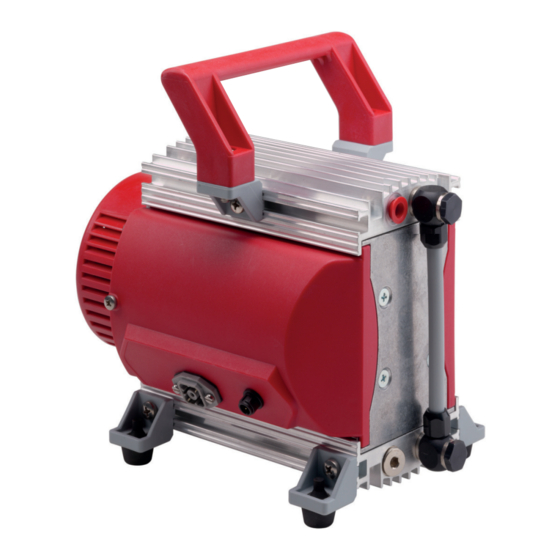
- Page 1 OPERATING INSTRUCTIONS Translation of the Original MVP 020-3 DC Diaphragm Pump...
- Page 2 Dear Customer, Thank you for choosing a Pfeiffer Vacuum product. Your new diaphragm pump is designed to support you with its performance, perfect operation and without impacting your individual application. The name Pfeiffer Vacuum stands for high-quality vacuum technology, a comprehensive and complete range of top-quality products and first-class service.
-
Page 3: Table Of Contents
Limits of use of the product Proper use Foreseeable improper use Personnel qualification 2.7.1 Ensuring personnel qualification 2.7.2 Personnel qualification for maintenance and repair 2.7.3 Advanced training with Pfeiffer Vacuum Product description Function Identifying the product Shipment Transportation and Storage... - Page 4 Table of contents Checking the final pressure Decommissioning Recycling and disposal General disposal information Dispose of diaphragm pumps Malfunctions Service solutions by Pfeiffer Vacuum Spare parts packages Accessories 13.1 Accessory information 13.2 Ordering accessories Technical data and dimensions 14.1 General 14.2 Technical data...
- Page 5 List of tables List of tables Tbl. 1: Stickers on the product Tbl. 2: Abbreviations used in this document Tbl. 3: Limits of use of the product Tbl. 4: Intake temperature limits of use Tbl. 5: Overview of connections on terminal block ST1B Tbl.
- Page 6 List of figures List of figures Fig. 1: Position of the labels on the product Fig. 2: Diaphragm pump design Fig. 3: Minimum distances Fig. 4: Circuit board with terminals Fig. 5: Connection to TC and TPS Fig. 6: Mounting the flushing gas nozzle Fig.
-
Page 7: About This Manual
Keep the manual for future consultation. 1.1 Validity This operating instructions is a customer document of Pfeiffer Vacuum. The operating instructions de- scribe the functions of the named product and provide the most important information for the safe use of the device. The description is written in accordance with the valid directives. The information in this op- erating instructions refers to the product's current development status. -
Page 8: Pictographs
Note 1.3.3 Stickers on the product This section describes all the stickers on the product along with their meaning. Rating plate Pfeiffer Vacuum D - 35614 Asslar Germany The rating plate is located on the cover of the electronics. MVP 020-3DC PK T01 198 24 V –... -
Page 9: Tbl. 2: Abbreviations Used In This Document
About this manual Abbreviation Meaning in this document Temperature (in °C), property abbreviation of the vacuum pump Turbopump electronic drive unit (turbo controller) Voltage supply (turbo power supply) Tbl. 2: Abbreviations used in this document 9/42... -
Page 10: Safety
Safety 2 Safety 2.1 General safety information The following 4 risk levels and 1 information level are taken into account in this document. DANGER Immediately pending danger Indicates an immediately pending danger that will result in death or serious injury if not observed. ►... - Page 11 Safety NOTICE Vacuum pump damage caused by overpressure Mixing up the connections causes overpressure overload. The vacuum pump can be started only against max. 1 bar differential pressure between inlet and outlet; otherwise the motor jams and sus- tains damage. ►...
- Page 12 Risks during maintenance, decommissioning and in event of malfunctions NOTICE Danger of property damage from improper maintenance Unprofessional work on the vacuum pump will lead to damage for which Pfeiffer Vacuum accepts no liability. ► We recommend taking advantage of our service training offering.
-
Page 13: Safety Precautions
Safety 2.3 Safety precautions DANGER Danger to life from electric shock Power supply packs that are not specified or are not approved will lead to severe injury to death. ► Make sure that the power supply pack meets the requirements for double isolation between mains input voltage and output voltage, in accordance with IEC 61010-1 IEC 60950-1 and IEC 62368-1. -
Page 14: Proper Use
► Use the vacuum pump for vacuum generation only. ► Adhere to the installation, commissioning, operating, and maintenance instructions. ► Do not use any accessory parts other than those recommended by Pfeiffer Vacuum. 2.6 Foreseeable improper use Improper use of the product invalidates all warranty and liability claims. Any use that is counter to the purpose of the product, whether intentional or unintentional, is regarded as improper use;... -
Page 15: Ensuring Personnel Qualification
─ Customer with Pfeiffer Vacuum service training ─ Pfeiffer Vacuum service technician 2.7.3 Advanced training with Pfeiffer Vacuum For optimal and trouble-free use of this product, Pfeiffer Vacuum offers a comprehensive range of courses and technical trainings. For more information, please contact Pfeiffer Vacuum technical training. -
Page 16: Product Description
(optional: flushing gas nozzle) 3.2 Identifying the product ► To ensure clear identification of the product when communicating with Pfeiffer Vacuum, always keep all of the information on the rating plate to hand. ► Learn about certifications through test seals on the product or at www.certipedia.com... -
Page 17: Transportation And Storage
Transportation and Storage 4 Transportation and Storage 4.1 Transporting the vacuum pump WARNING Danger of serious injury due to falling objects Due to falling objects there is a risk of injuries to limbs through to broken bones. ► Take particular care and pay special attention when transporting products manually. ►... -
Page 18: Installation
Property damage from contaminated gases Pumping down gases that contain impurities (condensate, particles) damages the vacuum pump. ► Use suitable filters or separators from the Pfeiffer Vacuum range of accessories, to protect the vacuum pump. Installation and operation of accessories Pfeiffer Vacuum offers a series of special, compatible accessories for its diaphragm pumps. -
Page 19: Connecting The Exhaust Side
► Observe the permissible pressures and pressure differentials for the product. ► Check the function of the exhaust line on a regular basis. Condensate separator Pfeiffer Vacuum recommends installing a condensate separator, with condensate drain at the lowest point of the exhaust line. Procedure 1. -
Page 20: Establishing Connections To The Rotation Speed Setting
Installation Fig. 4: Circuit board with terminals 1 Trimmer Terminal block ST1B (control signals) 2 LED for error code display Terminal block ST1A (voltage supply) Rotation speed set value Terminal block ST1B External through PWM signal black External through analog voltage black Internal via trimmer Cable cross-section = 0.25 mm... -
Page 21: Establishing A Connection For Interval Operation
Installation Establishing a connection for the trimmer 1. Make sure that no control signal is connected at the terminals of terminal block ST1B. 2. Connect the supply voltage at the corresponding terminals of terminal block ST1A. 5.4.2 Establishing a connection for interval operation Required cables (accessories) ●... -
Page 22: Operation
When pumping down dry gases, no special precautions are required. Pfeiffer Vacuum supplies the diaphragm pump ex factory for operation without control signal and with the trimmer turned to the right stop. The diaphragm pump starts directly and rotates at max. rotation speed. -
Page 23: Adjusting Rotation Speed
Operation 6.3 Adjusting rotation speed When operating the vacuum pump, there are 3 different control options, each of which can lead to a smooth circular runout of the vacuum pump at motor rotation speed > 400 rpm. The motor rotation speed of the vacuum pump increases linearly in each case up to max. rotation speed. The higher the motor rotation speed, the higher the pumping speed. -
Page 24: Switching Off The Vacuum Pump
Operation Required tool ● Allen key, WAF 5 Fig. 6: Mounting the flushing gas nozzle 1 Locking screw, G 1/8" Seal 2 Flushing gas nozzle (0.3 mm) Mounting the flushing gas nozzle Using the optional flushing gas nozzle improves the discharge of condensate, and the pump achieves the specified final vacuum more quickly. -
Page 25: Maintenance
► Do not use any alcohol or other cleaning agents to clean the diaphragms and valves. NOTICE Danger of property damage from improper maintenance Unprofessional work on the vacuum pump will lead to damage for which Pfeiffer Vacuum accepts no liability. ► We recommend taking advantage of our service training offering. -
Page 26: Checklist For Inspection And Maintenance
We recommend that Pfeiffer Vacuum Service carry out maintenance work at level 2. If the specified intervals are exceeded, or if maintenance work is carried out improperly, no war- ranty or liability claims are accepted on the part of Pfeiffer Vacuum. This also applies wher- ever parts other than original spare parts are used. -
Page 27: Dismantling The Diaphragms
Maintenance Prerequisites ● Handle dismantled ● Diaphragm pump supported Required tools ● Open-end wrench, WAF 15 ● Open-end wrench, WAF 16 ● Allen key, WAF 4 Fig. 7: Pump head and valves 1 Housing cover 1 Head cover (2×) 2 Cylinder screw (6×) Sealing ring (2×) 3 Lock washer (6×) Banjo bolt (2×) -
Page 28: Installing The Diaphragm
Maintenance Spare parts required ● Inspection set, including diaphragm key Required consumable materials ● Clean, dry cloth ● Alcohol or cleaning solvent, if necessary 1/2/3 Fig. 8: Replacing the diaphragms 1 Clamping washer Spacer disks 2 Diaphragm Pump head 2 3 Supporting washer Diaphragm key Dismantling the diaphragms... -
Page 29: Installing The Pump Head And Valves
Maintenance 3. Place the diaphragm (blue side up) and the supporting washer on the square of the clamping washer connecting screw. – Pay attention to the seating of the diaphragm in the square of the connecting screw. 4. Place the original spacer disks on the respective connection rod. 5. - Page 30 Maintenance Procedure 1. Measure the final pressure of the vacuum pump. – after work on the system, e.g., maintenance – before the vacuum pump is reinserted 2. Compare the measured final pressure with the test values and the specifications in the technical data.
-
Page 31: Decommissioning
Decommissioning 8 Decommissioning Before shutting down the vacuum pump, observe the following instructions to adequately protect the in- terior of the vacuum pump (suction chamber) from corrosion: Procedure for temporary vacuum pump shutdowns 1. Allow the vacuum pump to run on for 5 to 10 minutes with the vacuum connection open to allow any condensate that may be present to be removed from the vacuum pump. -
Page 32: Recycling And Disposal
– Fluoroelastomers (FKM) – Potentially contaminated components that come into contact with media 9.2 Dispose of diaphragm pumps Pfeiffer Vacuum diaphragm pumps contain materials that you must recycle. 1. Disconnect the electronic drive unit. 2. Dismantle the motor. 3. Decontaminate the components that come into contact with process gases. -
Page 33: Malfunctions
► Wear personal protective equipment if necessary. NOTICE Danger of property damage from improper maintenance Unprofessional work on the vacuum pump will lead to damage for which Pfeiffer Vacuum accepts no liability. ► We recommend taking advantage of our service training offering. -
Page 34: Tbl. 8: Troubleshooting On Diaphragm Pumps
● Valves dirty or defec- ● If necessary, clean or replace the tive valves and diaphragms. ● Connection rod or mo- ● Contact Pfeiffer Vacuum Service. tor bearing defective Tbl. 8: Troubleshooting on diaphragm pumps Fig. 10: LED on the circuit board... -
Page 35: Service Solutions By Pfeiffer Vacuum
We are always focused on perfecting our core competence – servicing of vacuum components. Once you have purchased a product from Pfeiffer Vacuum, our service is far from over. This is often exactly where service begins. Obviously, in proven Pfeiffer Vacuum quality. - Page 36 Service solutions by Pfeiffer Vacuum 5. Prepare the product for transport in accordance with the provisions in the contamination declaration. a) Neutralize the product with nitrogen or dry air. b) Seal all openings with blind flanges, so that they are airtight.
-
Page 37: Spare Parts Packages
Spare parts packages 12 Spare parts packages Ordering spare part packages ► Have the vacuum pump part number to hand, along with other details from the rating plate if nec- essary. ► Install original spare parts only. ► When ordering the inspection set, observe the respective part number of the diaphragm pump. Fig. -
Page 38: Accessories
Accessories 13 Accessories 13.1 Accessory information Power supply packs Power supply packs for fastening to the wall and standard rails or for rack assembly serve the voltage supply. Cable and adapter Mains, interface, connection, and extension cables provide a secure and suitable connection. Different lengths on request Hose connections Hose connections with adapters for connecting to a turbopump... -
Page 39: Technical Data And Dimensions
Technical data and dimensions 14 Technical data and dimensions 14.1 General Basis for the technical data of Pfeiffer Vacuum diaphragm pumps: ● Specifications according to PNEUROP committee PN5 ● ISO 21360:2012: “Vacuum technology - Standard methods for measuring vacuum-pump perform- ance - General description”... -
Page 40: Substances In Contact With The Media
Technical data and dimensions Classification MVP 020-3 DC Part number PK T01 198 Rotation speed 300 – 1 500 rpm Sound pressure level 45 dB(A) Motor version DC motor Cooling method Convection cooled Operating altitude, max. 2000 m Protection degree IP20, NEMA Type 1 (acc. to UL 50E) Ambient temperature 10 –... -
Page 41: Declaration Of Conformity
EN 61010-1: 2011 EN 61326-1: 2013 EN 61010-1: 2010 (Ed. 3) The authorized representative for the compilation of technical documents is Mr. Wolf- gang Bremer, Pfeiffer Vacuum GmbH, Berliner Straße 43, 35614 Asslar, Germany. Signature: Pfeiffer Vacuum GmbH Berliner Straße 43...
Need help?
Do you have a question about the MVP 20-3 DC and is the answer not in the manual?
Questions and answers