Pfeiffer Vacuum MVP 030-3 DC Operating Instructions Manual
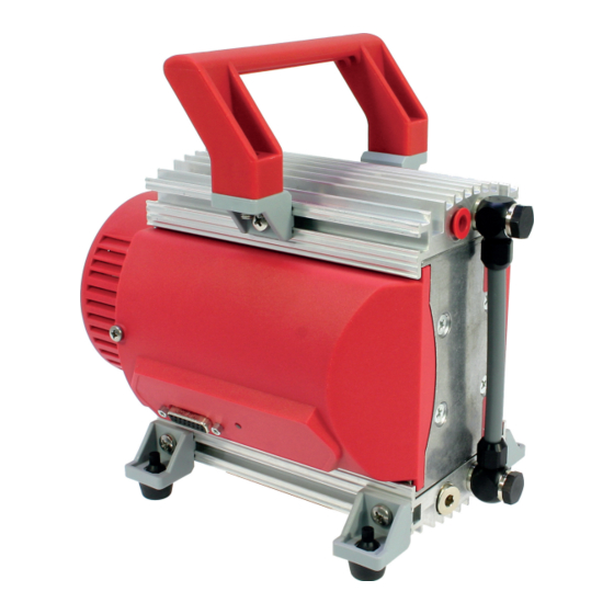
Diaphragm pump
Hide thumbs
Also See for MVP 030-3 DC:
- Operating instructions manual (50 pages) ,
- Operating instructions manual (56 pages) ,
- Operating instructions manual (42 pages)
Table of Contents
Advertisement
Quick Links
Advertisement
Table of Contents

Related Manuals for Pfeiffer Vacuum MVP 030-3 DC


Summary of Contents for Pfeiffer Vacuum MVP 030-3 DC
- Page 1 OPERATING INSTRUCTIONS Translation of the Original MVP 030-3 DC Diaphragm Pump...
-
Page 2: Telegram Example
Dear Customer, Thank you for choosing a Pfeiffer Vacuum product. Your new diaphragm pump is designed to support you with its performance, perfect operation and without impacting your individual application. The name Pfeiffer Vacuum stands for high-quality vacuum technology, a comprehensive and complete range of top-quality products and first-class service. -
Page 3: Table Of Contents
Limits of use of the product Proper use Foreseeable improper use Personnel qualification 2.7.1 Ensuring personnel qualification 2.7.2 Personnel qualification for maintenance and repair 2.7.3 Advanced training with Pfeiffer Vacuum Product description Function 3.1.1 Actuator 3.1.2 Pumping system 3.1.3 Cooling... - Page 4 Control commands Status requests Reference value inputs Operation Commissioning vacuum pump Switching on the vacuum pump Configuring connections with Pfeiffer Vacuum parameter set 8.3.1 Configuring the digital outputs 8.3.2 Selecting the interfaces Operating modes 8.4.1 Speed actuator operation 8.4.2 Standby mode 8.4.3 Normal operation...
- Page 5 Spart part package flushing gas nozzle Tbl. 25: Accessories Tbl. 26: Conversion table: Pressure units Tbl. 27: Conversion table: Units for gas throughput Tbl. 28: Technical data, MVP 030-3 DC Tbl. 29: Materials that make contact with the process media 5/58...
- Page 6 Flushing gas nozzle with filter Fig. 10: Handle Fig. 11: Pump head and valves Fig. 12: Replacing the diaphragms Fig. 13: Correct mounting orientation of the valves in the head cover Fig. 14: Spare parts Fig. 15: Dimensions MVP 030-3 DC 6/58...
-
Page 7: About This Manual
1.1.2 Variants These instructions apply to diaphragm pumps of the DC series: ● MVP 030-3 DC as standard version ● MVP 030-3 DC in the version for the integration in a pumping station (without handle and rubber feet) 1.2 Target group These operating instructions are aimed at all persons performing the following activities on the product: ●... -
Page 8: Pictographs
This section describes all the stickers on the product along with their meaning. Rating plate Pfeiffer Vacuum D - 35614 Asslar Rating plate of the diaphragm pump Germany MVP 030-3 DC PK T01 500 max. 7A 2019/09 24 V Pw: 64 W M: 4.3 kg... -
Page 9: Abbreviations
About this manual 1.3.4 Abbreviations Abbreviation Meaning in this document Direct current Nominal diameter (diamètre nominal) Electromagnetic compatibility Rotation speed value of a vacuum pump (frequency, in rpm or Hz) Fluorinated rubber Ground Light emitting diode Diaphragm vacuum pump Mean sea level [P:xxx] Electronic drive unit control parameters. -
Page 10: Safety
Safety 2 Safety 2.1 General safety information The following 4 risk levels and 1 information level are taken into account in this document. DANGER Immediately pending danger Indicates an immediately pending danger that will result in death or serious injury if not observed. ►... - Page 11 Safety CAUTION Danger of injury from bursting as a result of high pressure in the exhaust line Faulty or inadequate exhaust pipes lead to dangerous situations, e.g. increased exhaust pressure. There is a danger of bursting. Injuries caused by flying fragments, the escaping of high pressure, and damage to the unit cannot be excluded.
-
Page 12: Safety Precautions
Safety CAUTION Danger of injury from moving parts After a power failure or a standstill as a result of overheating, the motor restarts automatically. There is a risk of injury to fingers and hands if they enter the operating range of rotating parts. ►... -
Page 13: Limits Of Use Of The Product
► Use the vacuum pump for vacuum generation only. ► Adhere to the installation, commissioning, operating, and maintenance instructions. ► Use only accessory parts recommended by Pfeiffer Vacuum. 2.6 Foreseeable improper use Improper use of the product invalidates all warranty and liability claims. Any use that is counter to the purpose of the product, whether intentional or unintentional, is regarded as improper use;... -
Page 14: Personnel Qualification
The work described in this document may only be carried out by persons who have appropriate profes- sional qualifications and the necessary experience or who have completed the necessary training as provided by Pfeiffer Vacuum. Training people 1. Train the technical personnel on the product. -
Page 15: Personnel Qualification For Maintenance And Repair
─ Customer with Pfeiffer Vacuum service training ─ Pfeiffer Vacuum service technician 2.7.3 Advanced training with Pfeiffer Vacuum For optimal and trouble-free use of this product, Pfeiffer Vacuum offers a comprehensive range of courses and technical trainings. For more information, please contact Pfeiffer Vacuum technical training. -
Page 16: Product Description
3 Product description 3.1 Function The diaphragm pump of the MVP 030-3 DC series is a dry compressing vacuum pump with 3 pumping stages. The vacuum pump is a positive displacement pump with a periodic change in suction chamber size, produced by the movement of the diaphragm. The gas flow causes the valves to open and close automatically. -
Page 17: Identifying The Product
Product description 3.3 Identifying the product ► To ensure clear identification of the product when communicating with Pfeiffer Vacuum, always keep all of the information on the rating plate to hand. ► Learn about certifications through test seals on the product or at www.certipedia.com... -
Page 18: Transportation And Storage
Transportation and Storage 4 Transportation and Storage 4.1 Transporting the vacuum pump WARNING Danger of serious injury due to falling objects Due to falling objects there is a risk of injuries to limbs through to broken bones. ► Take particular care and pay special attention when transporting products manually. ►... -
Page 19: Installation
NOTICE Property damage from contaminated gases Pumping gases that contain contamination damages the vacuum pump. ► Use suitable filters or separators from the Pfeiffer Vacuum range of accessories, to protect the vacuum pump. Installation and operation of accessories Pfeiffer Vacuum offers a series of special, compatible accessories for its diaphragm pumps. -
Page 20: Connect Exhaust Side
► Install a suitable exhaust line. ► Wear hearing protection. Condensate separator Pfeiffer Vacuum recommends installing a condensate separator, with condensate drain at the lowest point of the exhaust line. Procedure 1. Check the installed silencer for free passage. -
Page 21: Establishing Electric Connection
Installation 5.4 Establishing electric connection DANGER Danger to life from electric shock Power supply packs that are not specified or are not approved will lead to severe injury to death. ► Make sure that the power supply pack meets the requirements for double isolation between mains input voltage and output voltage, in accordance with IEC 61010-1 IEC 60950-1 and IEC 62368-1. - Page 22 ► Insert the connection cable into the connection "DC out" on the power supply pack and close the bayonet lock. ► If you are using a Pfeiffer Vacuum control unit: Connect the “RS-485” connector to the control unit using a suitable extension cable.
-
Page 23: Interfaces
The following specifications are the factory settings for the electronic drive unit. Configuring “remote” interface ► Utilize the screened plug and cable. ► Configure the inputs and outputs via the Pfeiffer Vacuum parameter set. Fig. 6: Pins of the D-Sub socket, 15-pin Function... -
Page 24: Voltage Supply
Pin assignment of the D-Sub socket, 15-pin 6.1.1 Voltage supply Input/pin 1 The electrical connection is made using a connection cable from the Pfeiffer Vacuum accessory range or, by the customer, at pin 1 and pin 15. +24 V DC* output/pin 7 A connection with +24 V DC to pin 7 (active high) activates inputs 2 to 6. -
Page 25: Rs-485
Tbl. 8: Output DO2/pin 9 6.1.4 RS-485 Connecting RS-485 via D-Sub ► Connect a Pfeiffer Vacuum control unit or an external PC via pin 13 and pin 14 at the D-Sub con- nection of the electronic drive unit. 6.2 Interface RS-485 DANGER... -
Page 26: Connection Options Via Interface Rs-485
DC in M V P Fig. 8: Connection options via interface RS-485 Connecting Pfeiffer Vacuum control units or a PC ► Use the connection cable from the scope of delivery of the control unit or from the Pfeiffer Vacuum accessories. -
Page 27: Pfeiffer Vacuum Protocol For Rs-485 Interface
Interfaces 6.5 Pfeiffer Vacuum protocol for RS-485 interface 6.5.1 Telegram frame The telegram frame of the Pfeiffer Vacuum protocol contains only ASCII code characters [32; 127], the exception being the end character of the telegram C . Basically, a host (e.g. a PC) sends a tele- gram, which a device (e.g. -
Page 28: Data Types
Interfaces 6.5.4 Telegram example 2 Control command Switch on the pumping station (parameter [P:010], device address: "042" --> ASCII Control command understood Switch on the pumping station (parameter [P:010], device address: "042" --> ASCII 6.5.5 Data types Data type Description Length Example l1 –... -
Page 29: Parameter Set
Brief description of the parameters Functions Function description of the parameters Data type Type of formatting of the parameter for the use with the Pfeiffer Vacuum protocol Access type R (read): Read access; W (write): Write access Unit Physical unit of the described variable min. -
Page 30: Status Requests
Parameter set Indicator Designations Functions Data Unit min. max. type cess fault type SpdSet- Rotation 0 = off Mode speed setting 1 = on mode CtrlViaInt Operate via in- 1 = remote terface 2 = RS-485 4 = PV.can 32 = Keys on the front panel 255 = Interface selection IntSelLckd Interface se-... -
Page 31: Reference Value Inputs
Parameter set 7.4 Reference value inputs Indicator Designations Functions Data Access Unit min. max. default type type SpdSVal Set value in rotation Set rotation speed setting mode speed in x.x% of the nominal rotation speed StdbySVal Rotation speed set value 66.7 in stand-by operation RS485Adr RS-485 Interface address... -
Page 32: Operation
Operation 8 Operation 8.1 Commissioning vacuum pump WARNING Danger of poisoning due to toxic process media escaping from the exhaust pipe During operation with no exhaust line, the vacuum pump allows exhaust gases and vapors to escape freely into the air. There is a risk of injury and fatality due to poisoning in processes with toxic process media. -
Page 33: Configuring Connections With Pfeiffer Vacuum Parameter Set
● Operation via an external control unit ● Operation via RS-485 and Pfeiffer Vacuum control unit or PC The connection of a Pfeiffer Vacuum control unit permits the controlling of the vacuum pump via the pa- rameters fixed in the electronic drive unit. -
Page 34: Speed Actuator Operation
3. Check the set rotation speed (parameter [P:308] or [P:397]). 8.4.2 Standby mode Pfeiffer Vacuum recommends standby mode for during process and production stops. With active stand-by mode, the electronic drive unit reduces the speed of the vacuum pump in the range of 30 to 100% of the nominal speed. -
Page 35: Pumping Condensable Vapors
Operation Setting the related parameters 1. Set the parameter [P:002] to "0". 2. Set the parameter [P:026] to "0". 3. Check the set rotation speed (parameter [P:308]). 8.5 Pumping condensable vapors Vapors or moisture from pumped media impair the throughput after condensation in the vacuum pump. Using the optional flushing gas nozzle improves the discharge of condensate, and the pump achieves the specified final vacuum more quickly. -
Page 36: Operation Monitoring
Operation 8.6 Operation monitoring 8.6.1 Operating mode display via LED The LED on the electronic drive unit indicates the basic operating conditions. A differentiated error and warning display is only possible for operation with a Pfeiffer Vacuum control unit. Indicator Activity Meaning None ●... -
Page 37: Maintenance
► Do not use any alcohol or other cleaning agents to clean the diaphragms and valves. NOTICE Danger of property damage from improper maintenance Unprofessional work on the vacuum pump will lead to damage for which Pfeiffer Vacuum accepts no liability. ► We recommend taking advantage of our service training offering. -
Page 38: Checklist For Inspection And Maintenance
We recommend that Pfeiffer Vacuum Service carry out maintenance work. If the specified intervals are exceeded, or if maintenance work is carried out improperly, no warranty or lia- bility claims are accepted on the part of Pfeiffer Vacuum. This also applies wherever parts other than original spare parts are used. -
Page 39: Change The Diaphragms And Valves
Maintenance Fig. 10: Handle 1 Handle Screw (2×) 2 Housing cover Groove Dismantling the handle 1. Loosen the screws of the handle. 2. Push the handle from the groove in the housing cover. Installing the handle 1. Push the handle into the groove in the housing cover. 2. -
Page 40: Dismantling The Diaphragms
Maintenance Fig. 11: Pump head and valves 1 Housing cover 1 Head cover (2×) 2 Cylinder screw (6×) Sealing ring (2×) 3 Lock washer (6×) Banjo bolt (2×) 4 Valve (4×) Hose connection Procedure 1. Loosen the screw fitting. 2. Turn the elbow fitting max. 1/4 revolution anti-clockwise, until the hose connection can be loos- ened. -
Page 41: Installing The Diaphragm
Maintenance 1/2/3 Fig. 12: Replacing the diaphragms 1 Clamping washer Spacer disks 2 Diaphragm Pump head 2 3 Supporting washer Diaphragm key Dismantling the diaphragms 1. Carefully bend the diaphragm up on the side and while it is bent, attach the diaphragm key to the supporting washer. -
Page 42: Installing The Pump Head And Valves
Maintenance 9.4.4 Installing the pump head and valves Avoid interchanging components Always dismantle and mount only the pump head on one pump side in order to avoid inter- changing the components. The procedures are identical for both pump heads. Prerequisite ● Diaphragms installed Required tools ●... - Page 43 Maintenance Prerequisites ● Vacuum pump mounted ● Vacuum pump correctly installed electrically Required aids ● Vacuum chamber (3 liter) ● Pressure gauge ● Flushing gas nozzle (optional) Measuring final pressure 1. Connect a vacuum chamber (volume approx. 3 l) to a vacuum connection. 2.
-
Page 44: Decommissioning
Decommissioning 10 Decommissioning Before shutting down the vacuum pump, observe the following instructions to adequately protect the in- terior of the vacuum pump (suction chamber) from corrosion: Procedure for temporary vacuum pump shutdowns 1. Allow the vacuum pump to run on for 5 to 10 minutes with the vacuum connection open to allow any condensate that may be present to be removed from the vacuum pump. -
Page 45: Recycling And Disposal
– Fluoroelastomers (FKM) – Potentially contaminated components that come into contact with media 11.2 Dispose of diaphragm pumps Pfeiffer Vacuum diaphragm pumps contain materials that you must recycle. 1. Disconnect the electronic drive unit. 2. Dismantle the motor. 3. Decontaminate the components that come into contact with process gases. -
Page 46: Malfunctions
► Wear personal protective equipment if necessary. NOTICE Danger of property damage from improper maintenance Unprofessional work on the vacuum pump will lead to damage for which Pfeiffer Vacuum accepts no liability. ► We recommend taking advantage of our service training offering. -
Page 47: Error Codes
Warnings (* Warning F –––– *) do not cause the vacuum pump to be switched off. Handling malfunction messages 1. Read out error codes via Pfeiffer Vacuum control units or a PC. 2. Remove the cause of the malfunction. 3. Reset the malfunction message with parameter [P:009]. -
Page 48: Service Solutions By Pfeiffer Vacuum
We are always focused on perfecting our core competence – servicing of vacuum components. Once you have purchased a product from Pfeiffer Vacuum, our service is far from over. This is often exactly where service begins. Obviously, in proven Pfeiffer Vacuum quality. - Page 49 Service solutions by Pfeiffer Vacuum 5. Prepare the product for transport in accordance with the provisions in the contamination declaration. a) Neutralize the product with nitrogen or dry air. b) Seal all openings with blind flanges, so that they are airtight.
-
Page 50: Spare Part Packages
Spare part packages 14 Spare part packages Ordering spare part packages ► Have the vacuum pump part number to hand, along with other details from the rating plate if nec- essary. ► Install original spare parts only. ► When ordering the inspection set, observe the respective part number of the diaphragm pump. Fig. -
Page 51: Tbl. 24: Spart Part Package Flushing Gas Nozzle
Spare part packages Spare part package Order number comprising the following parts Filter P 0105 405 Flushing gas nozzle filter Tbl. 24: Spart part package flushing gas nozzle 51/58... -
Page 52: Accessories
Flushing gas connection Avoids moisture accumulating in the vacuum pump 15.2 Ordering accessories OmniControl variants You can find additional OmniControl variants on the Pfeiffer Vacuum website. Selection field Part number OmniControl 200, rack unit with integrated power supply pack PE D50 000 0... -
Page 53: Technical Data And Dimensions
Technical data and dimensions 16 Technical data and dimensions 16.1 General Basis for the technical data of Pfeiffer Vacuum diaphragm pumps: ● Specifications according to PNEUROP committee PN5 ● ISO 21360:2012: “Vacuum technology - Standard methods for measuring vacuum-pump perform- ance - General description”... -
Page 54: Substances In Contact With Media
45 dB(A) 45 dB(A) Weight 4.3 kg 4.3 kg 4.3 kg Tbl. 28: Technical data, MVP 030-3 DC 16.3 Substances in contact with media Pump parts Substances in contact with media Housing cover Aluminum alloy (AlMgSi) Head cover Aluminum alloy (AlMgSi) -
Page 55: Dimensions
Technical data and dimensions 16.4 Dimensions G1/8" silencer G1/8" Fig. 15: Dimensions MVP 030-3 DC Dimensions in mm 55/58... -
Page 56: Ec Declaration Of Conformity
DIN EN IEC 61326-1:2022 DIN EN ISO 80079-36:2016 DIN EN 1127-1:2019 The authorized representative for the compilation of technical documents is Dr. Adrian Wirth, Pfeiffer Vacuum GmbH, Berliner Straße 43, 35614 Asslar, Germany. Signature: Pfeiffer Vacuum GmbH Berliner Straße 43... -
Page 57: Declaration Of Conformity
EN IEC 61326-1:2021 EN ISO 80079-36:2016 EN 1127-1:2019 The manufacturer's authorized representative in the United Kingdom and the authorized agent for compiling the technical documentation is Pfeiffer Vacuum Ltd, 16 Plover Close, In- terchange Park, MK169PS Newport Pagnell. Signature: Pfeiffer Vacuum GmbH Berliner Straße 43...
Need help?
Do you have a question about the MVP 030-3 DC and is the answer not in the manual?
Questions and answers