Table of Contents
Advertisement
Quick Links
Advertisement
Table of Contents

Subscribe to Our Youtube Channel
Related Manuals for National Instruments PXIe-1095


Summary of Contents for National Instruments PXIe-1095
- Page 1 PXIe-1095 User Manual 2022-07-06...
-
Page 2: Table Of Contents
PXIe-1095 Backplane Overview........ - Page 3 PXIe-1095 User Manual LED Indicators............. . 22 Remote Voltage Monitoring and Control.
-
Page 4: Pxi Express Chassis Manual
This manual contains the functional overview and specifications for your PXI Express chassis. Getting Started This section describes the key features of the PXIe-1095 chassis and lists the kit contents and optional equipment you can order from National Instruments. Unpacking Carefully inspect the shipping container and the chassis for damage. -
Page 5: Key Features
The chassis’ modular design ensures a high level of maintainability, resulting in a very low mean time to repair (MTTR). The PXIe-1095 chassis fully complies with the PXI-5 PXI Express Hardware Specification, offering advanced timing and synchronization features. -
Page 6: High Reliability
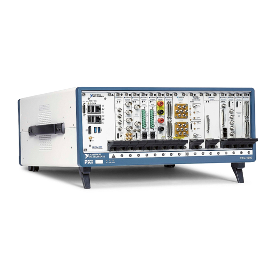
Field replaceable power supply ■ Multi-Chassis Support PXI Express System Timing Slot for tight synchronization across multiple ■ chassis Switchless CLK10 routing ■ Chassis Components The following figures show key features of the PXIe-1095 chassis front and back panels. ni.com... - Page 7 PXIe-1095 User Manual Figure 10. Front View of the PXIe-1095 PXIe-1088 LOW POWER 1. System Controller Expansion Slot 2. Backplane Connectors 3. PXI Express Hybrid Peripheral Slots (8x) 4. PXI Express System Controller Slot 5. Dip Switch 6. Power Inhibit Switch 7.
-
Page 8: Optional Equipment
3. Power Supply Fan Exhaust 4. Chassis Protective Earth Terminal 5. Kensington Slot Optional Equipment Contact NI to order the following options for the PXIe-1095 chassis. EMC Filler Panels EMC filler panel kits are available from NI. Rack Mount Kits Rack mounting kits are available from NI that can accommodate a variety of rack depths. -
Page 9: Replacement Fan Kit
A fan kit available from NI includes both side and PXI module fan assemblies. Interoperability with CompactPCI The design of the PXIe-1095 provides you the flexibility to use the following devices in a single PXI Express chassis: PXI Express compatible products ■... -
Page 10: Hybrid Peripheral Slots
PXIe-1095 User Manual System slot link 2 is a Gen-3 x16 PCI Express link to the primary PCI Express switch, providing a nominal bandwidth of 16 GB/s (single direction) between the system controller slot and logical PCI Express switch 2. PXI Express peripheral slots 5-9 are connected to logical PCI Express switch 2 with Gen-3 x8 PCI Express links and are downstream of system slot link 2. -
Page 11: Pxi Express Peripheral Slots
The hybrid peripheral slots provide full PXI Express functionality and 32-bit PXI functionality except for PXI Local Bus. The hybrid peripheral slot only connects to PXI Local Bus 6 left and right. Figure 3. PXIe-1095 PCI Express Backplane Diagram Primary PCIe Switch... -
Page 12: Pxi Local Bus
PXIe-1095 User Manual hybrid peripheral slot can link up to a Gen-3 x8 PCI Express, providing a maximum nominal single-direction bandwidth of 8 GB/s. A PXI Express Peripheral with x8, x4, or x1 PCI Express link to the system slot ■... -
Page 13: Pxi Trigger Bus
PXIe-1095 User Manual The backplane routes PXI Local Bus 6 between all slots. The left local bus 6 from slot 1 is not routed anywhere, and the right local bus 6 from slot 9 is not routed anywhere. Local bus signals may range from high-speed TTL signals to analog signals as high as 42 V. -
Page 14: System Reference Clock
Dotted line connections are available only with the Timing and Synchronization upgrade. System Reference Clock The PXIe-1095 chassis supplies PXI_CLK10, PXIe_CLK100 and PXIe_SYNC100 to every peripheral slot with an independent driver for each signal. The following figure shows the chassis reference clock architecture. - Page 15 SMA connector on the rear of the chassis (Timing and Synchronization upgrade). When an external clock is detected, the backplane automatically phase- locks the PXI_CLK10, PXIe_CLK100, and PXIe_SYNC100 signals to this external clock and distributes these signals to the slots. Refer to the PXIe-1095 Specifications © National Instruments...
-
Page 16: Safety Information
PXIe-1095 User Manual section for the specification information for an external clock provided on the PXI_CLK10_IN pin of the System Timing Slot or rear panel SMA. Safety Information Caution Before undertaking any troubleshooting, maintenance, or exploratory procedure, carefully read the following caution notices. -
Page 17: Chassis Cooling Considerations
You must adhere to the cooling clearances as outlined in the following section. Providing Adequate Clearance The module and power supply exhaust vents for the PXIe-1095 are on the top of the chassis. The module intake vents are on the rear of the chassis. There are also intake and exhaust vents located along the sides of the chassis. - Page 18 PXIe-1095 User Manual Figure 8. PXIe-1095 Cooling Clearances 44.45 mm (1.75 in.) 44.45 mm (1.75 in.) Peripheral Expansion Slot Provides Power For Multi-Slot Modules, Refer To User Manual For Details PXIe-1092 TEMP FANS FANS FANS USE ONLY COMPATIBLE RACK MOUNT KITS.
- Page 19 PXIe-1095 User Manual Figure 9. PXIe-1095 Vents 1. PXI Module Air Intake (2x) 2. Power Supply Intake 3. PXI Module Air Exhaust Vent 4. Power Supply Air Exhaust Vent 5. Timing and Synchronization Upgrade Air Exhaust Vent 6. Timing and Synchronization Upgrade Air Intake 7.
-
Page 20: Chassis Ambient Temperature Definition
Rack Mounting Rack mount applications require optional rack mount kits available from NI. Refer to the instructions supplied with the rack mount kits to install your PXIe-1095 chassis in an instrument rack. Note You must remove the feet and carry handle from the PXIe-1095 chassis when rack mounting. -
Page 21: Connecting The Safety Ground
Connecting the Safety Ground Caution The PXIe-1095 chassis are designed with a three-position IEC 60320 C14 inlet for the U.S. that connects the ground line to the chassis ground. For proper grounding, a suitable cordset must be used to connect this inlet to an appropriate earth safety ground. -
Page 22: Connecting To A Power Source
PXIe-1095 User Manual Connecting to a Power Source Caution Do not install modules prior to performing the following power- on test. To completely remove power, you must disconnect the AC power cable. Attach input power through the rear AC inlet using the appropriate AC power cable supplied. -
Page 23: Remote Voltage Monitoring And Control
Table 3. Rear Power Supply LED States Remote Voltage Monitoring and Control The PXIe-1095 chassis supports remote voltage monitoring and inhibiting through a female 8-pin connector on the rear panel. The following table shows the pinout of the 8-pin connector. - Page 24 When connecting digital voltmeter probes to the rear 8-pin connector, be careful not to short the probe leads together. You can use a digital voltmeter to ensure all voltage levels in the PXIe-1095 chassis are within the allowable limits. Referring to the following table, connect one lead of the voltmeter to a supply pin on the 8-pin remote voltage monitoring connector on the rear panel.
-
Page 25: Pxi Express System Configuration With Max
PXIe-1095 User Manual If the voltages fall within the specified ranges, the chassis complies with the CompactPCI voltage-limit specifications. PXI Express System Configuration with MAX The PXI Platform Services software included with your chassis automatically identifies your PXI Express system components to generate a pxiesys.ini file. You can configure your entire PXI system and identify PXI-1 chassis through Measurement &... -
Page 26: Maintenance
System controllers from NI provide the pxisys.ini file for the PXIe-1095 chassis, so you should not need to use the chassis.ini file. Refer to the documentation provided with the system controller or to ni.com/support... -
Page 27: Cleaning
PXIe-1095 User Manual Note Many components within the chassis are susceptible to static discharge damage. Service the chassis only in a static-free environment. Observe standard handling precautions for static-sensitive devices while servicing the chassis. Always wear a grounded wrist strap or equivalent while servicing the chassis. -
Page 28: Replacing The Power Supply
Identify the two mounting screws for the PXIe-1095 that attach the power supply to the chassis. Refer to the Rear View of the PXIe-1095 Chassis figure, for the screw locations. Using a Phillips screwdriver, remove the screws. Pull on the rear of the power supply to remove it from the back of the chassis. -
Page 29: Installation
Connecting the Safety Ground Caution The PXIe-1095 chassis are designed with a three-position IEC 60320 C14 inlet for the U.S. that connects the ground line to the chassis ground. For proper grounding, a suitable cordset must be used to connect this inlet to an appropriate earth safety ground. -
Page 30: Connecting To A Power Source
Be sure the tab catches on the bottom of the slot. 2. Rotate the fan module upwards. 3. Pinch both snaps at the top of the fan module, rotate the module until it is flush with the chassis, and release the snaps. ni.com © 2022 National Instruments Corporation.
Need help?
Do you have a question about the PXIe-1095 and is the answer not in the manual?
Questions and answers