Table of Contents
Advertisement
Available languages
Available languages
Quick Links
H-2533
SUPPLY CABINET
PAGE 1 OF 15
1-800-295-5510
uline.com
Pour le français, consulter les page 11-15.
TOOLS NEEDED
CAUTION! Some parts may have sharp
edges. Take care when handling various
pieces to avoid injury. For safety, wear work
gloves when assembling.
Para Español, vea páginas 6-10.
11/32" Nut Driver
(included)
Flathead Screwdriver
Hammer
0723 IH-2533
Advertisement
Table of Contents

Related Manuals for U-Line H-2533BL


Summary of Contents for U-Line H-2533BL
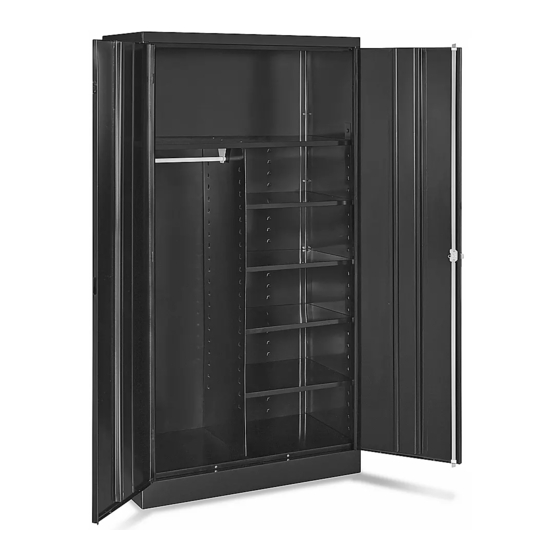
- Page 1 Para Español, vea páginas 6-10. Pour le français, consulter les page 11-15. H-2533 1-800-295-5510 uline.com SUPPLY CABINET TOOLS NEEDED 11/32" Nut Driver (included) Flathead Screwdriver Hammer CAUTION! Some parts may have sharp edges. Take care when handling various pieces to avoid injury. For safety, wear work gloves when assembling.
- Page 2 PARTS PRIMARY ASSEMBLY HANDLE ASSEMBLY DESCRIPTION QTY. DESCRIPTION QTY. Back Panel Left Door Right Door Left Side Right Side Hinge Pin Door Handle With Keys Sill Shelf Lock Bar Locking Cam Bottom Partition Lock Bar Guide Cotter Pin Coat Rod Bracket #8-32 x 3/8"...
- Page 3 ASSEMBLY INSTRUCTIONS ASSEMBLING CABINET 4. Insert the shelf (5) into the third from top position on the shelf adjustment strips. Do this by inserting 1. Place the back panel (1) on a protected surface. the shelf edges into the lances on all four strips. Be The bottom flange should be facing upward.
- Page 4 ASSEMBLY INSTRUCTIONS CONTINUED 6. Place the bottom (6) in the bottom lances of the shelf Figure 7 adjustment strips. The flange with two holes should face the front, and it should hang over the sill. Bolt to the sill with two bolts and nuts. (See Figure 5) Figure 5 9.
-
Page 5: Attaching Handle
ASSEMBLY INSTRUCTIONS CONTINUED ATTACHING HANDLE Figure 10 Figure 11 1. Place the door handle (15) on the right hand door and fasten with two slotted bolts and lockwashers. (See Figure 10) 2. Turn the handle to the open position (parallel to the ground) and hook the lock bars (16) to the locking cam (17). -
Page 6: Herramientas Necesarias
H-2533 800-295-5510 uline.mx GABINETE DE SUMINISTROS HERRAMIENTAS NECESARIAS Llave de Tuercas de 11/32" (incluida) Desarmador de Cabeza Plana Martillo ¡PRECAUCIÓN! Algunas partes pueden tener bordes filosos. Tenga cuidado al manipular las distintas piezas para evitar lesiones. Para seguridad, use guantes de trabajo para ensamblar las partes. - Page 7 PARTES ENSAMBLE PRIMARIO ENSAMBLE DEL ASA DESCRIPCIÓN CANT. DESCRIPCIÓN CANT. Panel Posterior Puerta Izquierda Puerta Derecha Lado Izquierdo Lado Derecho Clavija de la Bisagra Asa de la Puerta con Llaves Umbral Repisa Barra de Seguridad Leva con Seguro Parte Inferior Separador Guía de la Barra de Seguridad Pasador de Chaveta...
-
Page 8: Instrucciones De Ensamble
INSTRUCCIONES DE ENSAMBLE ENSAMBLE DEL GABINETE 4. Inserte la repisa (5) en la tercera posición desde arriba en las tiras de ajuste de las repisas. Hágalo 1. Coloque el panel posterior (1) sobre una superficie insertando los bordes de la repisa en la lanceta protegida. - Page 9 CONTINUACIÓN DE INSTRUCCIONES DE ENSAMBLE 6. Coloque la parte inferior (6) en las lancetas inferiores Diagrama 7 de las tiras de ajuste de las repisas. La pestaña con dos orificios debe mirar hacia delante y debe colgar por encima del umbral. Fíjela al umbral con dos pernos y tuercas.
- Page 10 CONTINUACIÓN DE INSTRUCCIONES DE ENSAMBLE COLOCACIÓN DEL ASA Diagrama 10 Diagrama 11 1. Coloque el asa de bloqueo de la puerta (15) sobre la puerta derecha y fíjela con dos pernos ranurados y rondanas de seguridad. (Vea Diagrama 10) 2. Gire el asa a la posición de abierto (paralela al piso) y fije las barras de seguridad (16) a la leva con seguro (17).
-
Page 11: Outils Requis
H-2533 1-800-295-5510 uline.ca ARMOIRE POUR FOURNITURES OUTILS REQUIS Tournevis à douille de 11/32 po (inclus) Tournevis à tête plate Marteau MISE EN GARDE! Certaines pièces peuvent avoir des bords tranchants. Faites attention lorsque vous manipulez les diverses pièces, afin d'éviter les blessures. Pour votre sécurité, portez des gants de travail lors du montage. - Page 12 PIÈCES ENSEMBLE PRINCIPAL ENSEMBLE DE LA POIGNÉE DESCRIPTION QTÉ DESCRIPTION QTÉ Panneau arrière Porte gauche Porte droite Panneau latéral gauche Panneau latéral droit Axe de charnière Poignée de porte avec clés Seuil de cadre Tablette Barre de verrouillage Came de verrouillage Dessous de l'armoire Cloison Guide de barre de verrouillage...
-
Page 13: Instructions De Montage
INSTRUCTIONS DE MONTAGE MONTAGE DE L'ARMOIRE 4. Insérez la tablette (5) à la troisième position en partant du haut des bandes de réglage des 1. Placez le panneau arrière (1) sur une surface tablettes. Faites ceci en insérant les bords de la protégée. - Page 14 INSTRUCTIONS DE MONTAGE SUITE 6. Placez le dessous de l'armoire (6) dans les supports Figure 7 de tablette inférieurs des bandes de réglage des tablettes. La bride avec deux trous doit être orientée vers l'avant, et elle doit reposer sur le seuil de cadre. Boulonnez le dessous de l'armoire au seuil de cadre à...
-
Page 15: Fixation De La Poignée
INSTRUCTIONS DE MONTAGE SUITE FIXATION DE LA POIGNÉE Figure 10 Figure 11 1. Placez la poignée de porte (15) sur la porte droite et fixez à l'aide de deux boulons fendus et deux rondelles de blocage. (Voir Figure 10) 2. Tournez la poignée en position ouverte (parallèle au sol) et accrochez les barres de verrouillage (16) à...
Need help?
Do you have a question about the H-2533BL and is the answer not in the manual?
Questions and answers