Table of Contents
Advertisement
Available languages
Available languages
Quick Links
P2.120 G-U(TC)
P2.160 G-U(TC)
P2.210 G-U(TC)
Originele bedieningshandleiding
Voor de gespecialiseerde vakman
Aangeblazen gasbrander
Original operating instructions
For specialist installation engineers
Gas burners
de, fr, it................................. 4200 1050 5400
............................................. 4200 1050 3100
11/2016 - Art. Nr. 4200 1050 6000C
nl
en
Advertisement
Chapters
Table of Contents

Related Manuals for elco P2.120 G-U


Summary of Contents for elco P2.120 G-U
- Page 1 P2.120 G-U(TC) P2.160 G-U(TC) P2.210 G-U(TC) Originele bedieningshandleiding Voor de gespecialiseerde vakman Aangeblazen gasbrander Original operating instructions For specialist installation engineers Gas burners de, fr, it......... 4200 1050 5400 ..........4200 1050 3100 11/2016 - Art. Nr. 4200 1050 6000C...
-
Page 2: Table Of Contents
Voor iedere andere vorm van gebruik is bij de overdracht, een gebruiks- en gastoestellen toestemming vereist van ELCO. onderhoudsaanwijzing te overhandigen. Installatie, inbedrijfstelling en onderhoud Deze dient in de plaatsingsruimte van de Gasleidingen... -
Page 3: Branderbeschrijving
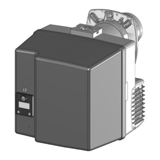
Overzicht Branderbeschrijving Branderautomaat Display- en bedieningseenheid Meetbrug Luchtdrukbewaker Ventilatormotor Ontsteker Knop voor het afstellen van maat Y Sluiterschijf voor propaangas Branderhuis Bevestiging van de basisplaat (Onderhoud) Branderbuis 7-polige aansluiting (bedekt) Gasblokaansluitflens Branderkap Ontgrendelingsknop Bevestigingsschroef van de kap 103B Luchtregeling Luchtkast 11/2016 - Art. -
Page 4: Werkingsfunctie Zonder Afdichtingscontrole Veiligheidsfunctie
De sonde is geïsoleerd op - De brander is gereed om te werken door de fabrikant in overleg met ELCO. de gaskop gemonteerd en voert door de Functie: stuwschijf naar de vlamzone. De sonde... -
Page 5: Werkingsfunctie Met Afdichtingscontrole Veiligheidsfunctie
De vlam wordt bewaakt door een goedgekeurd door de fabrikant in voorhanden is, volgt nog een wachttijd ionisatiesonde. De sonde is geïsoleerd overleg met ELCO. van 2 minuten. De wachttijd kan alleen op de gaskop gemonteerd en voert door Functie: door een spanningsonderbreking van de stuwschijf naar de vlamzone. -
Page 6: Branderautomaat Tcg 1Xx
Functie Branderautomaat TCG 1xx Standaardfunctie zonder afdichtingscontrole De gasbranderautomaat TCG 1xx stuurt en De knop R … veroorzaakt ... bewaakt de aangeblazen brander. Door het indrukken tijdens microprocessorgestuurde programmaverloop worden uiterst stabiele tijden bereikt, die onafhankelijk zijn van … 1 seconde ... Ontgrendelen van de schommelingen in netspanning en automaat omgevingstemperatuur. -
Page 7: Branderautomaat Tcg 1Xx
Functie Branderautomaat TCG 1xx Standaardfunctie met afdichtingscontrole De knop R … veroorzaakt ... De gasbranderautomaat stuurt en indrukken tijdens bewaakt de aangeblazen brander. Door het computergestuurde programmaverloop worden uiterst … 1 seconde ... Ontgrendelen van de stabiele tijden bereikt, die onafhankelijk automaat zijn van schommelingen in netspanning …... -
Page 8: Branderautomaat Tcg 1Xx
Functie Branderautomaat TCG 1xx Snelle start met voortdurende werking van de motor Snelle start met lange voorventilatie Snelle start met voortdurende werking van de motor Fasen functieverloop: Motor ingeschakeld, controle Naontstekingstijd geen spanning luchtdruk Werking Spanningsvoeding voorhanden, Voorventilatie Branderstilstand geen aanvraag tot warmte Voorontsteking, activering van Naventilatie Aanvraag tot warmte, controle... -
Page 9: Aansluitschema Aansluitsokkel
Functie Aansluitschema Aansluitsokkel Afstandsontgren Vlamcontrole Gaspressostaat Luchtpressostaat Stroomvoeding L1 Aarde deling Stekker Klem Aarde Magneetventiel Brandermotor Ontstekin Display Storing Stekker Klem Klem Benaming Stekker nr. Klem Benaming Stekker nr. Signaal vlamdoofveiligheid Fase onstekingstransformator Neutraal Neutraal Fase Fase brandermotor Signaal afstandsontgrendeling Aarde Fase Neutraal... -
Page 10: Gasblok Mb-Dle
Functie Gasblok MB-DLE Het compacte gasblok MB-DLE ... met P2.G ingebouwde gasdrukregelaar is bestemd voor gasbranders met geforceerde luchttoevoer met een snelheid. Het compacte gasblok draagt de goedkeuring CE 0085 AP3156. Technische gegevens Ingangsdruk 13-360 mbar Omgevingstemperatuur -15 tot +60°C Spanning 230 V / 50 Hz Opgenomen vermogen... -
Page 11: Montage Van De Brander
Montage Montage van de brander Montage van de brander Inbouwen: De branderflens 3 is uitgerust met • Aansluitflens 3 met bouten 4 aan de langgaten en kan voor een gat- van 150 ketel bevestigen - 184mm worden gebruikt. Deze maten •... -
Page 12: Montage Van De Gasarmatuur Controle Van De Branderkop Voor Aardgas / Propaan
Montage Montage van de gasarmatuur Controle van de branderkop voor aardgas / propaan Montage van de gasarmatuur • Controleren of ringafdichting J1 aanwezig is en correct op de flens ligt. • Gasarmatuur rechts of links met spoelen in bovenste verticale stand bevestigen. -
Page 13: Elektrische Aansluiting
Inbedrijfstelling Elektrische aansluiting Controles vóór de inbedrijfstelling Ionisatiestroommeting Algemene voorschriften voor worden gebruikt. gasverzorging Bij de inbedrijfstelling van de brander • De aansluiting van de gasarmatuur op wordt de installatie gelijktijdig onder het gasnet mag alleen door een verantwoording van de installateur of erkend vakman worden uitgevoerd. -
Page 14: Instelgegevens
Inbedrijfstelling Instelgegevens P o sitie Bra n d e rve rm o g e n M a a t Y Ka m e rd ru k In ste llin g g a skle p lu ch tkle g a sd ru k b ij d e ko p p Br (m b a r) (kW ) (m m ) (m b a r) -
Page 15: Luchtregeling
Inbedrijfstelling Luchtregeling Luchtregeling De luchtregeling in de branderkop De regeling van de verbrandingslucht beïnvloedt behalve de luchthoeveelheid gebeurt op twee plaatsen: ook de mengzone en de luchtdruk in de • aan drukzijde via de spleet tussen de branderbuis. vlammenhaker en branderbuis. - Verdraaien van de schroef A •... -
Page 16: Instelling Compacte Gaseenheid Mb-Dle
Inbedrijfstelling Instelling compacte gaseenheid MB-DLE Verbeterde startgedrag door plaatje Instelling drukregelaar Instelling startlasthoeveelheid - Voor het instellen van de uitgangsdruk snelslaginstelling zijn 60 slagen van de instelschroef • Beschermkap 5 eraf draaien en over mogelijk. Drie slagen rechtsom 180° gedraaid als regelgereedschap verhogen de druk met 1 mbar, drie gebruiken. -
Page 17: Instelling Gaspressostaat, Luchtpressostaat
Inbedrijfstelling Instelling gaspressostaat Instelling luchtpressostaat Werkingscontrole Instelling gaspressostaat De instelwaarde van de gasdrukschakelaar • Voor instelling van de uitschakeldruk: Het moet hoger liggen dan de ventilatordruk, deksel van de gaspressostaat verwijderen. maar lager dan de gasdruk na het gasventiel. •... -
Page 18: Onderhoud
Service Onderhoud Onderhoudswerkzaamheden aan de ketel In het kader van het jaarlijks onderhoud - Functiecontrole van de vlambewaker en aan de brander aanbevolen van de branderautomaat en brander mogen uitsluitend door een werkzaamheden: - Inschakelen van de brander erkende verwarmingsmonteur worden - Test van de brander, meting bij aankomst in - Gasdoorstroming controleren uitgevoerd. - Page 19 Service Onderhoud Vervangen van de vlambuis Reinigen van de kap Voor dit proces is het noodzakelijk om • Geen chloorhoudende of schurende de brander uit te bouwen. middelen gebruiken. • Klembout van aansluitflens • Kap met water en een losdraaien. schoonmaakmiddel schoonmaken.
-
Page 20: Storingen Verhelpen
Service Storingen verhelpen Oorzaken en verhelpen van Als de storing blijft bestaan, de volgende Gebruik alleen originele storingen tabel gebruiken. onderdelen van de fabrikant. Bij storingen moeten de principiële voorwaarden voor een goede werking De componenten die met veiligheid Aanwijzing: worden gecontroleerd: verband houden, mogen niet worden... -
Page 21: Aanduiding Onderhoudsinterval
Service Aanduiding onderhoudsinterval Gedurende de werking kunnen na enige tijd de volgende inlichtingen verschijnen: Dat betekent dat het tijd is voor onderhoud door een vakman. Als de installateur zijn telefoonnummer heeft opgetekend, dan verschijnt dat, alsook het nummer van het afgesloten onderhoudscontract (toegankelijk via het... -
Page 22: Contents
30697 within their respective performance gas burners to a heat generator maintenance instructions on or before final range. Any other type of application requires the approval of ELCO. delivery. These instructions should be EN 60335-1, -2-102 displayed in a prominent location at the... -
Page 23: Burner Description
Overview Burner description Control and safety unit Display Measuring bridge Air pressure switch Blower motor Igniter Adjusting screw for dimension Y Sealing washer for Liquefied Petroleum Gas Housing Plate hanging device (Maintenance) Burner tube 7-pin connector (covered) Gas train connecting flange Cover Release knob Hood securing screw... -
Page 24: Operating Function Without Leakage Test Safety Function
- The burner is ready for operation the purpose by the manufacturer in probe. The probe is fitted with insulation to consultation with ELCO. the gas head and is routed through the Function: turbulator into the flame zone. The probe... -
Page 25: Operating Function With Leakage Test Safety Function
This is followed by a further for the purpose by the manufacturer start attempt. If there is still no gas Monitoring in consultation with ELCO. pressure, a further waiting time of 2 The flame is monitored by an ionisation Function: minutes follows. -
Page 26: Control Unit Tcg 1Xx Standard Function Without Leakage Test
Function Control unit TCG 1xx Standard function without leakage test The TCG 1xx automatic gas combustion Pressing and ... leads to ... control unit controls and monitors the forced- holding the R draught burner. The microprocessor- button for ... controlled programme sequence ensures maximum stability of time periods, regardless …... -
Page 27: Control Unit Tcg 1Xx Standard Function With Leakage Test
Function Control unit TCG 1xx Standard function with leakage test Pressing and ... leads to ... The TCG 1xx automatic gas combustion control unit controls and monitors the holding the R forced draught burner. The button for ... microprocessor-controlled program …... -
Page 28: Control Unit Tcg 1Xx
Function Control unit TCG 1xx Quick start with continuous motor operation Quick start with longer preventilation Quick start with continuous motor operation Functional sequence phases: Motor on, check air pressure Operation no voltage Preventilation Burner stop Power supply on, no heat Pre-ignition, activation of Postventilation request... -
Page 29: Allocation Chart Connection Socket
Function Allocation chart Connection socket Remote Air pressure Flame monitor Gas pressostat L1 power supply Earth unlocking switch Connector Terminal Earth Solenoid valve Burner motor Firing Malfunction light Connector Terminal Terminal Designation Connector no. Terminal Designation Connector no. Flame monitor signal Ignition transformer phase Neutral Neutral... -
Page 30: Mb-Dle Gas Train
Function MB-DLE gas train The MB-DLE ... compact gas train with P2.G integrated gas pressure regulator is suitable for use with single-stage forced draught gas burners. The compact gas train bears the CE 0085 AP3156 approval marking. Technical data Inlet pressure 13-360mbar Ambient temperature -15 to +60°C Voltage... -
Page 31: Burner Assembly
Assembly Burner assembly Burner assembly Installation: Burner flange 3 is equipped with • Secure connecting flange 3 to the elongated holes and can be used with a boiler using screws 4 hole circle diameter of 150 - 184mm. • Fit pipe bracket 2 to the burner pipe These dimensions comply with EN 226. -
Page 32: Gas Train Assembly, Checking The Mixing Unit For Natural Gas / Propane Gas
Assembly Gas train assembly Checking the mixing unit for natural gas / propane gas Gas train assembly • Check the correct position of the O-ring J1 in the gas connecting flange. • Secure the gas train on the burner head so that the gas train coils are in the upper vertical position. -
Page 33: Electrical Connection
Commissioning Electrical connection Checks before commissioning Ionisation current measurement General regulations applying to the specified by the draft combustion gas connection ordinance. • The gas train must only be connected It is the responsibility of the fitter or his to the gas mains by a recognised representative to obtain approval for the specialist. -
Page 34: Adjustment Data
Commissioning Adjustment data Furna ce Burne r Dim e nsion Air fla p Ga s va lve se tting pre ssure pow e r se tting Ga s he a d pre ssure pBr (m ba r) (kW ) (m m ) (°) (m ba r) MB-...412... -
Page 35: Air Regulation
Commissioning Air regulation Air regulation The regulation of air in the Combustion air is regulated at two combustion head influences not only points: the airflow but also the mixing zone and the air pressure in the burner tube. • on the pressure side, by the gap - Turning screw A: between the turbulator and the burner tube. -
Page 36: Setting The Mb-Dle Compact Gas Unit
Commissioning Setting the MB-DLE compact gas unit Improved starting characteristics using the orifice plate Pressure controller setting Initial load flow adjustment - rapid The adjusting screw has a path of 60 stroke adjustment turns for adjusting the output pressure. • Twist off protective cap 5 and turn it Three turns clockwise or anti-clockwise through 180°... -
Page 37: Setting The Gas Pressostat, Air Pressure Switch Adjustment
Commissioning Setting the gas pressostat Air pressure switch adjustment Operating check Setting the gas pressostat The gas pressostat adjustment value must be • To set the shut-off pressure: Remove the higher than the blower pressure but lower cover of the gas pressostat. than the gas pressure downstream of the gas •... -
Page 38: Maintenance
Servicing Maintenance Burner and boiler servicing must only be Work recommended as part of annual - Flame monitor and automatic carried out by a professionally qualified burner maintenance: combustion control unit function check heating engineer. The system operator is - Burner test run, input measurement in - Commissioning the burner advised to take out a maintenance the boiler room... - Page 39 Servicing Maintenance Replacing the flame tube Cleaning the cover It is necessary to remove the burner for • Do not use abrasive products or this work. products containing chlorine. • Loosen the clamping screw on the • Clean the cover with water and a connecting flange.
-
Page 40: Troubleshooting
Maintenance Troubleshooting Fault diagnosis and repair If the malfunction persists, use the Only use original spare parts. Faults following table. In the event of a malfunction, first check It is not permitted to repair any After each operation: that the prerequisites for correct components relevant to safety. -
Page 41: Maintenance Frequency Indicator
Servicing Maintenance frequency indicator After a certain period of operation, the following information may be displayed: This means that maintenance must be carried out by a specialist. If the fitter has registered his telephone number, then this appears, as well as the number of the completed service contract (accessible... - Page 42 11/2016 - Art. Nr. 4200 1050 6000C...
- Page 43 11/2016 - Art. Nr. 4200 1050 6000C...
- Page 44 Gefabriceerd in de EU. Made in EU. Niet-contractueel document. Non contractual document. 11/2016 - Art. Nr. 4200 1050 6000C...
Need help?
Do you have a question about the P2.120 G-U and is the answer not in the manual?
Questions and answers