Subscribe to Our Youtube Channel
Summary of Contents for RTS UIO-256
-
Page 1: User Manual
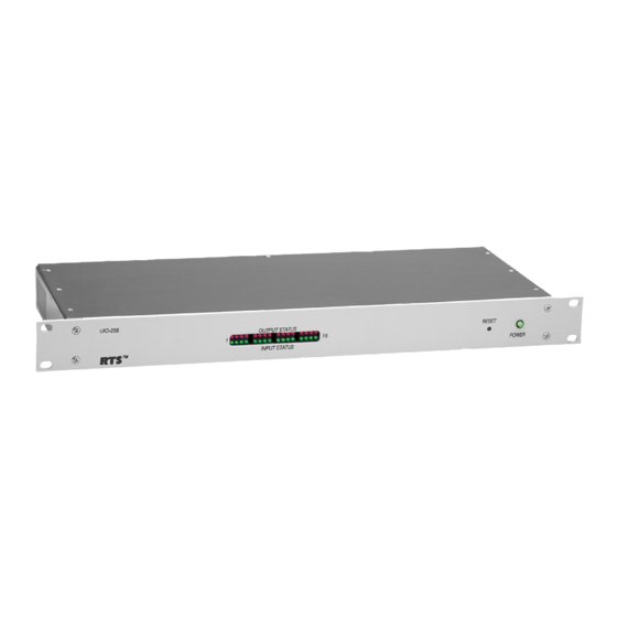
USER MANUAL Model UIO-256 Universal Input/ Output Frame 9330-7499-000 Rev F, 02/2005... - Page 2 Proprietary Notice The RTS product information and design disclosed herein were originated by and are the property of Telex Communications, Inc. Telex reserves all patent, propri- etary design, manufacturing, reproduction, use and sales rights thereto, and to any article disclosed therein, except to the extent rights are expressly granted to others.
-
Page 3: Table Of Contents
4.3 Mounting ... 5 4.4 Multi-Drop Connections ... 6 4.4.1 UIO-256 to ADAM System ... 6 4.4.2 UIO-256 to ADAM CS System ... 6 4.4.3 UIO-256 Frame Interconnections ... 7 4.4.4 UIO-256 to Zeus System... 7 4.5 GPI Output and Input Connections ... 7 4.6 Power Connection ... -
Page 4: Introduction
2 of the UIO-256 firmware . GPI inputs are connected via a 50-pin telco connector on the back of the UIO-256. Each input requires =5 to +18 VDC for activation. The positive input and common connections may be provided from a remote source. -
Page 5: System Firmware 9.2.1 Or Newer
16 UIO-256 frames are allowed to be connected together. 4.1.2 System Firmware Older than 9.2.1 The UIO-256 must be configured to work in Token Ring mode. Set DIP switch 1-2 to the OPEN position. Up to four UIO-256 frames are allowed to be connected together. -
Page 6: Multi-Drop Connections
Connect the end of the 9-pin cable marked ADAM System to J3 of the XCP-ADAM-MC Master Controller Breakout Panel. Connect the end marked UIO-256 to J2 of the UIO-256 Frame. If you need a longer cable, you can construct one using the wiring diagram in Figure 5. -
Page 7: Uio-256 Frame Interconnections
Figure 5. ADAM to UIO-256 Cable 4.4.3 UIO-256 Frame Interconnections If more than one UIO-256 frame is used, construct a Y- cable as shown in Figure 3 or 4 with additional DB-9S connectors in parallel with the ADAM and ADAM CS connector. -
Page 8: Assigning The Gpi Inputs And Outputs
7 7 7 7 7 * Dependent on UIO-256 DIP switch SW1 settings for Input/Output range as summarized in Table 1. ** The relay contacts are rated for 0.5A at 120 VAC; 1A at 24 VDC; 0.3A at 60 VDC Table 3. -
Page 9: Operation
“+” input pin, and connect the external common to the negative “-” input pin. The UIO-256 also has an internal 18 VDC source, which is available at pins 18 and 22. -
Page 10: Fuse Replacement
Fuse Replacement The fuse is accessible on the rear panel power module of the UIO-256. Remove the power cord from the power module and free the fuse cartridge as shown Figure 7. Be sure to replace the fuse with a fuse of the same rating and type. - Page 12 Telex Communications, Inc. • 12000 Portland Avenue South • Burnsville, MN 55337...


Need help?
Do you have a question about the UIO-256 and is the answer not in the manual?
Questions and answers