Sign In
Upload
Download
Table of Contents
Contents
Add to my manuals
Delete from my manuals
Share
URL of this page:
HTML Link:
Bookmark this page
Add
Manual will be automatically added to "My Manuals"
Print this page
×
Bookmark added
×
Added to my manuals
Manuals
Brands
RTS Manuals
Intercom System
BP-4000
Technical manual
RTS BP-4000 Technical Manual
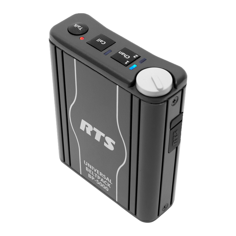
Universal beltpack
Hide thumbs
1
2
3
4
Table Of Contents
5
6
7
8
9
10
11
12
13
14
15
16
17
18
19
20
21
22
23
24
25
26
27
28
29
30
31
32
33
34
35
36
page
of
36
Go
/
36
Contents
Table of Contents
Troubleshooting
Bookmarks
Table of Contents
Important Safety Instructions
Table of Contents
Introduction
Features
Reference View
External Connections and Controls
Connector Description
XLR (3-Pin)
XLR (4-Pin)
XLR (5-Pin)
Specifications
System Configuration and Power
System Configuration
Power
Channel Power
Local Power
Initial Setup and Configuration
Initial BP-4000/5000 Setup
UBP (Universal Beltpack) Initialization Troubleshooting Table
Setup Mode Indication
Mode-Sensing Setup
Firmware Version
Programming the Beltpack
Enter Program Menu
Exit Program Menu
Menu System
Mode Menu
Talk Mode Menu
MIC Gain Menu
Sidetone Adjust Menu
Incoming Call Beep Menu
Channel Lock Menu (RTS Mode Only)
Power Source Menu (RTS Mode Only)
MIC Kill Menu (RTS and Audiocom Mode Only)
Send MIC Kill Menu (RTS and Audiocom Mode Only)
Leds Menu
Factory Reset
Operation and Maintenance
Operation
Adjust the Volume
Change the Channel (BP-5000)
Maintenance
Replace the Beltclip
Set Local Power
Advertisement
Quick Links
1
External Connections and Controls
2
System Configuration and Power
3
Programming the Beltpack
4
Menu System
Download this manual
Universal Beltpack
Technical Manual
BP-4000 & BP-5000
Rev. 02
November/2017
F.01U.321.601
Table of
Contents
Previous
Page
Next
Page
1
2
3
4
5
Advertisement
Table of Contents
Need help?
Do you have a question about the BP-4000 and is the answer not in the manual?
Ask a question
Questions and answers
Related Manuals for RTS BP-4000
Intercom System RTS BP300 User Manual
Portable belt pack user station (33 pages)
Intercom System RTS BP317 User Manual
Portable belt pack user station (15 pages)
Intercom System RTS BP317 User Manual
Portable belt pack user station (15 pages)
Intercom System RTS BP320 Technical Data Manual
Portable belt user station (9 pages)
Intercom System RTS BP320 Technical Data Manual
Portable belt user station (8 pages)
Intercom System RTS BP-319 Specifications
Two-wire intercom (2 pages)
Intercom System RTS BP-319 Operating Instructions Manual
Beltpacks rtstw intercom systems (18 pages)
Intercom System RTS BP-319 User Manual
User station (10 pages)
Intercom System RTS BP-319 User Manual
User station two wire intercom series (8 pages)
Intercom System RTS BP-325 User Manual
Belt-pack intercom station (28 pages)
Intercom System RTS BP325 User Manual
Belt-pack intercom station (16 pages)
Intercom System RTS BP325 User Manual
Belt-pack intercom station (24 pages)
Intercom System RTS BP-5000 Technical Manual
Universal beltpack (36 pages)
Intercom System RTS BP-6000 Technical Manual
Universal beltpack (32 pages)
Intercom System RTS TKP-4 User Instructions
Adam, adam cs, and zeus intercom systems (27 pages)
Intercom System RTS BTR-800 Operating Instructions Manual
Professional wireless intercom system (88 pages)
This manual is also suitable for:
Bp-5000
Table of Contents
Print
Rename the bookmark
Delete bookmark?
Delete from my manuals?
Login
Sign In
OR
Sign in with Facebook
Sign in with Google
Upload manual
Upload from disk
Upload from URL


Need help?
Do you have a question about the BP-4000 and is the answer not in the manual?
Questions and answers