
Related Manuals for SMC Networks ProtoCessor FPC-ED2


Summary of Contents for SMC Networks ProtoCessor FPC-ED2
- Page 1 Start-up Guide ProtoCessor FPC-ED2 For Interfacing VorTek Products Document Revision: 2.A Web Configurator VorTek ProtoCessor Start-up Guide MSAsafety.com...
- Page 2 Technical Support Thank you for purchasing the ProtoCessor for VorTek. Please call VorTek for technical support of the ProtoCessor product. MSA Safety does not provide direct support. If VorTek needs to escalate the concern, they will contact MSA Safety for assistance. Support Contact Information: VorTek Instruments 8475 W I-25 Frontage Rd, Suite 300...
- Page 3 Quick Start Guide 1. Record the information about the unit. (Section 2.1) 2. Connect the ProtoCessor FPC-ED2 3 pin RS-485 port to the field protocol cabling. (Section 3.1) 3. Connect a PC to the ProtoCessor via Ethernet cable. (Section 4) 4.
-
Page 4: Table Of Contents
2.2.2 Set Node-ID for the Device ...................... 8 Interfacing ProtoCessor to Devices ....................9 ProtoCessor FPC-ED2 Showing Connection Ports..............9 Serial Network: Wiring Field Port to RS-485 Network ............10 Connect the PC to the ProtoCessor ..................... 11 Connecting to the Gateway via Ethernet ................11 4.1.1... - Page 5 10.5.2 Edit the Certificate Loaded onto the FieldServer ..............44 10.6 Change User Management Settings ..................45 10.6.1 Create Users .......................... 46 10.6.2 Edit Users ..........................47 10.6.3 Delete Users ........................... 48 10.6.4 Change FieldServer Password ....................49 10.7 Grid Connection Warning Message ..................50 10.8 System Status Button ......................
- Page 6 Figure 1: ProtoCessor Part Numbers ........................8 Figure 2: COM Settings ............................8 Figure 3: ProtoCessor FPC-ED2 ........................... 9 Figure 4: Connection from ProtoCessor to RS-485 Field Network ..............10 Figure 5: RS-485 EOL & Bias Resistor Switches ....................10 Figure 6: Ethernet Port Location .........................
-
Page 7: Introduction
Description Introduction ProtoCessor Gateway The ProtoCessor is an embedded module that is designed into VorTek’s product (hereafter simply called “device”) and is preconfigured to support Modbus RTU, Modbus TCP/IP, BACnet MS/TP and BACnet/IP. It is not necessary to download any configuration files to support the required applications. The ProtoCessor is pre-loaded with tested profiles/configurations for the supported device. -
Page 8: Setup For Protocessor
Setup the Gateway Setup for ProtoCessor Record Identification Data Each ProtoCessor has a unique part number located on the side or the back of the unit. This number should be recorded, as it may be required for technical support. The numbers are as follows: Model Part Number ProtoCessor... -
Page 9: Interfacing Protocessor To Devices
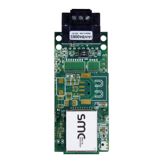
Installing the Gateway Interfacing ProtoCessor to Devices ProtoCessor FPC-ED2 Showing Connection Ports Figure 3: ProtoCessor FPC-ED2 VorTek ProtoCessor Start-up Guide... -
Page 10: Serial Network: Wiring Field Port To Rs-485 Network
Installing the Gateway Serial Network: Wiring Field Port to RS -485 Network • Connect the RS-485 network wires to the 3-pin RS-485 connector on the ProtoCessor as shown below in Figure Use standard grounding principles for RS-485 GND • See Section for information on connecting to an Ethernet network. -
Page 11: Connect The Pc To The Protocessor
Setup Web Server Security Connect the PC to the ProtoCessor Connecting to the Gateway via Ethernet Connect a Cat-5 Ethernet cable (straight through or cross-over) between the local PC and ProtoCessor. Ethernet Port Figure 6: Ethernet Port Location 4.1.1 Changing the Subnet of the Connected PC The default IP Address for the ProtoCessor is 192.168.1.24, Subnet Mask is 255.255.255.0. -
Page 12: Setup Web Server Security
Setup Web Server Security Setup Web Server Security Navigate to the IP Address of the ProtoCessor on the local PC by opening a web browser and entering the IP Address of the ProtoCessor; the default address is 192.168.1.24. NOTE: If the IP Address of the ProtoCessor has been changed, the assigned IP Address can be discovered using the FS Toolbox utility. -
Page 13: Figure 9: Warning Expanded Text
Setup Web Server Security • Additional text will expand below the warning, click the underlined text to go to the IP Address. In example this text is “Proceed to 10.40.50.94 (unsafe)”. Figure 9 Figure 9: Warning Expanded Text • When the login screen appears, put in the Username (default is “admin”) and the Password (found on the label of the FieldServer). -
Page 14: Select The Security Mode
Setup Web Server Security Select the Security Mode On the first login to the FieldServer, the following screen will appear that allows the user to select which mode the FieldServer should use. Figure 11: Security Mode Selection Screen NOTE: Cookies are used for authentication. NOTE: To change the web server security mode after initial setup, go to Section 10.5. -
Page 15: Https With Own Trusted Tls Certificate
Setup Web Server Security 5.2.1 HTTPS with Own Trusted TLS Certificate This is the recommended selection and the most secure. Please contact your IT department to find out if you can obtain a TLS certificate from your company before proceeding with the Own Trusted TLS Certificate option. -
Page 16: Configure Network Settings
Configuring the Gateway Configure Network Settings Navigate to the Network Settings • From the Web App landing page, click the Settings tab on the left side of the screen. Figure 13: Generic Web App Landing Page • Click the Network tab that appears to open the Network Settings page. Figure 14: Settings Tabs •... -
Page 17: Change The Protocessor Ip Address
Configuring the Gateway Change the ProtoCessor IP Address • Enable DHCP to automatically assign IP Settings or modify the IP Settings manually as needed, via these fields: IP Address, Netmask, Gateway, and Domain Name Server1/2. NOTE: If the FieldServer is connected to a router, the IP Gateway of the FieldServer should be set to the same IP Address of the router. -
Page 18: Grid User Setup, Registration And Login
Configuring the Gateway Grid User Setup, Registration and Login The Grid is MSA Safety’s device cloud solution for IIoT. Integration with the Grid enables a secure remote connection to field devices through a FieldServer and hosts local applications for device configuration, management, as well as maintenance. -
Page 19: Figure 18: Grid Fieldserver Manager Opt Out Warning Window
Configuring the Gateway • Either go through the Grid setup to integrate cloud functionality to the FieldServer or optout of Grid setup. For Grid setup, continue with instructions in the following sections To opt out of Grid setup, click on a tab other than the FieldServer Manager tab, click the checkbox next to “Opt out”... -
Page 20: User Setup
Configuring the Gateway User Setup Before the gateway can be connected to the Grid a user account must be created. Request an invitation to the Grid from the manufacturer’s support team and follow the instructions below to set up login details: •... -
Page 21: Figure 20: Setting User Details
Configuring the Gateway • Click the “Complete Registration” button and fill in user details accordingly. Figure 20: Setting User Details • Fill in the name, phone number, password fields and click the checkbox to agree to the privacy policy and terms of service. NOTE: If access to data logs using RESTful API is needed, do not include “#”... -
Page 22: Registration Process
Configuring the Gateway Registration Process Once Grid user credentials have been generated, the ProtoCessor can be registered onto the Grid server. • When first logging onto the ProtoCessor, the Web App will open on the Grid FieldServer Manager page. NOTE: If a warning message appears instead, go to Section 10.7 to resolve the connection issue. -
Page 23: Figure 22: Grid Registration - Installer Details
Configuring the Gateway • To register, fill in the user details, site details, gateway details and Grid account credentials. Enter user details and click Next Figure 22: Grid Registration – Installer Details Enter the site details by entering the physical address fields or the latitude and longitude then click Next Figure 23: Grid Registration –... -
Page 24: Figure 24: Grid Registration - Gateway Details
Configuring the Gateway Enter Name and Description (required) then click Next Figure 24: Grid Registration – Gateway Details Enter user credentials and click Register Device Figure 25: Grid Registration – Grid Account VorTek ProtoCessor Start-up Guide... -
Page 25: Figure 26: Device Registered For The Grid
Configuring the Gateway • Once the device has successfully been registered, a confirmation window will appear. Click the Close button and the following screen will appear listing the device details and additional information auto-populated by the ProtoCessor. Figure 26: Device Registered for the Grid NOTE: Update these details at any time by going to the FieldServer Manager tab and clicking the Update Device Details button. -
Page 26: Login To The Grid
Configuring the Gateway Login to the Grid After the ProtoCessor is registered, go to www.smccloud.net and type in the appropriate login information as per registration credentials. Figure 27: Grid Login Page NOTE: If the login password is lost, see the MSA Grid Start-up Guide for recovery instructions. -
Page 27: Figure 28: Grid Landing Page
Configuring the Gateway NOTE: For additional Grid instructions see the MSA Grid Start-up Guide. Figure 28: Grid Landing Page VorTek ProtoCessor Start-up Guide... -
Page 28: Configure The Protocessor
Configuring the Gateway Configure the ProtoCessor Navigate to the ProtoCessor Web Configurator • From the Web App landing page (Figure 29), click the Settings tab and then click Configuration. Figure 29: Web App Landing Page NOTE: For information on the System Status button, go to Section 10.8. •... -
Page 29: Select Field Protocol And Set Configuration Parameters
Configuring the Gateway Select Field Protocol and Set Configuration Parameters • On the Web Configurator page, the first configuration parameter is the Protocol Selector. Figure 31: Web Configurator Protocol Selector Parameter • Select the field protocol by entering the appropriate number into the Protocol Selector Value. Click the Submit button. -
Page 30: Setting Protocessor Active Profiles
Configuring the Gateway Setting ProtoCessor Active Profiles • In the Web Configurator, the Active Profiles are shown below the configuration parameters. The Active Profiles section lists the currently active device profiles, including previous Web Configurator additions. This list is empty for new installations, or after clearing all configurations. (Figure Figure 32: Web Configurator Showing no Active Profiles VorTek ProtoCessor Start-up Guide... -
Page 31: Verify Device Communications
Configuring the Gateway • To add an active profile to support a device, click the Add button under the Active Profiles heading. This will present a profile drop-down menu underneath the Current profile column. • Once the Profile for the device has been selected from the drop-down list, enter the value of the device’s Node-ID as 1. -
Page 32: Bacnet: Setting Node_Offset To Assign Specific Device Instances
Configuring the Gateway BACnet: Setting Node_Offset to Assign Specific Device Instances • Follow the steps outlined in Section to access the ProtoCessor Web Configurator. • Node_Offset field shows the current value (default = 50,000). The values allowed for a BACnet Device Instance can range from 1 to 4,194,303 •... -
Page 33: Troubleshooting
Additional Information Troubleshooting Lost or Incorrect IP Address • Ensure that FieldServer Toolbox is loaded onto the local PC. Otherwise, download the FieldServer-Toolbox.zip via the MSA Safety website. • Extract the executable file and complete the installation. Ethernet Port Figure 36: Ethernet Port Location •... -
Page 34: Viewing Diagnostic Information
Additional Information Viewing Diagnostic Information • Type the IP Address of the ProtoCessor into the web browser or use the FieldServer Toolbox to connect to the ProtoCessor. • Click on Diagnostics and Debugging Button, then click on view, and then on connections. •... -
Page 35: Checking Wiring And Settings
Additional Information Checking Wiring and Settings • No COMS on Modbus RTU side. If the Tx/Rx LEDs are not flashing rapidly then there is a COM issue. To fix this, check the following: Visual observations of LEDs on ProtoCessor (Section 9.4) Check baud rate, parity, data bits, stop bits Check device address Verify wiring... -
Page 36: Led Diagnostics For Communications Between Protocessor And Devices
Additional Information LED Diagnostics for Communications Between ProtoCessor and Devices See the diagram below for ProtoCessor FPC-ED2 LED Locations. Description The Run LED will start flashing 20 seconds after power indicating normal operation. The Heat Beat LED has the same functionality but flashes more rapidly. -
Page 37: Taking A Fieldserver Diagnostic Capture
Additional Information Taking a FieldServer Diagnostic Capture When there is a problem on-site that cannot easily be resolved, perform a Diagnostic Capture before contacting support. Once the Diagnostic Capture is complete, email it to technical support. The Diagnostic Capture will accelerate diagnosis of the problem. If the FieldServer bios is updated/released on November 2017 or later then the Diagnostic Capture is performed via the gateway’s on-board system. -
Page 38: Taking A Capture With Older Firmware
Additional Information 9.5.1 Taking a Capture with Older Firmware If the FieldServer firmware is from before November 2017, the Diagnostic Capture can be done by downloading the FieldServer Toolbox software but network connections (such as Ethernet and Wi-Fi) cannot be captured (if a network diagnostic is needed take a Wire Shark capture). Once the Diagnostic Capture is complete, email it to technical support. - Page 39 Additional Information Select “Full Diagnostic" from the drop down menu NOTE: If desired, the default capture period can be changed. Click on the Start Diagnostic button Wait for the capture period to finish and the Diagnostic Test Complete window will appear •...
-
Page 40: Additional Information
Additional Information 10 Additional Information 10.1 Update Firmware To load a new version of the firmware, follow these instructions: 1. Extract and save the new file onto the local PC. 2. Open a web browser and type the IP Address of the FieldServer in the address bar. Default IP Address is 192.168.1.24 Use the FS Toolbox utility if the IP Address is unknown (Section 9.1) 3. -
Page 41: Internet Browser Software Support
Additional Information 10.3 Internet Browser Software Support The following web browsers are supported: • Chrome Rev. 57 and higher • Firefox Rev. 35 and higher • Microsoft Edge Rev. 41 and higher • Safari Rev. 3 and higher NOTE: Internet Explorer is no longer supported as recommended by Microsoft. NOTE: Computer and network firewalls must be opened for Port 80 to allow FieldServer GUI to function. -
Page 42: Change Web Server Security Settings After Initial Setup
Additional Information 10.5 Change Web Server Security Settings After Initial Setup NOTE: Any changes will require a FieldServer reboot to take effect. • From the FS-GUI page, click Setup in the Navigation panel. Figure 41: FS-GUI Page VorTek ProtoCessor Start-up Guide... -
Page 43: Change Security Mode
Additional Information 10.5.1 Change Security Mode • Click Security in the Navigation panel. Figure 42: FS-GUI Security Setup • Click the Mode desired. If HTTPS with own trusted TLS certificate is selected, follow instructions in Section 5.2.1 • Click the Save button. VorTek ProtoCessor Start-up Guide... -
Page 44: Edit The Certificate Loaded Onto The Fieldserver
Additional Information 10.5.2 Edit the Certificate Loaded onto the FieldServer NOTE: A loaded certificate will only be available if the security mode was previously setup as HTTPS with own trusted TLS certificate. • Click Security in the Navigation panel. Figure 43: FS-GUI Security Setup – Certificate Loaded •... -
Page 45: Change User Management Settings
Additional Information 10.6 Change User Management Settings • From the FS-GUI page, click Setup in the Navigation panel. • Click User Management in the navigation panel. NOTE: If the passwords are lost, the unit can be reset to factory settings to reinstate the default unique password on the label. -
Page 46: Create Users
Additional Information 10.6.1 Create Users • Click the Create User button. Figure 45: Create User Window • Enter the new User fields: Name, Security Group and Password. User details are hashed and salted NOTE: The password must meet the minimum complexity requirements. An algorithm automatically checks the password entered and notes the level of strength on the top right of the Password text field. -
Page 47: Edit Users
Additional Information 10.6.2 Edit Users • Click the pencil icon next to the desired user to open the User Edit window. Figure 46: Setup Users • Once the User Edit window opens, change the User Security Group and Password as needed. Figure 47: Edit User Window •... -
Page 48: Delete Users
Additional Information 10.6.3 Delete Users • Click the trash can icon next to the desired user to delete the entry. Figure 48: Setup Users • When the warning message appears, click Confirm. Figure 49: User Delete Warning VorTek ProtoCessor Start-up Guide... -
Page 49: Change Fieldserver Password
Additional Information 10.6.4 Change FieldServer Password • Click the Password tab. Figure 50: FieldServer Password Update via FS-GUI • Change the general login password for the FieldServer as needed. NOTE: The password must meet the minimum complexity requirements. An algorithm automatically checks the password entered and notes the level of strength on the top right of the Password text field. -
Page 50: Grid Connection Warning Message
Additional Information 10.7 Grid Connection Warning Message • If a warning message appears instead of the page as shown in Figure 21, follow the suggestion that appears on screen. If the ProtoCessor cannot reach the Grid server, the following message will appear Figure 51: Grid Connection Problems Message •... -
Page 51: System Status Button
Additional Information 10.8 System Status Button The System Status Button can be found on any page of the web apps. This shows the level of alert/functionality for the customer device. This is an aggregate of the Web App page’s resource usage upon the local PC or mobile device, Grid connectivity and device alert level. -
Page 52: Routing Settings
Additional Information 10.9 Routing Settings The Routing settings make it possible to set up the IP routing rules for the FieldServer’s internet and network connections. • Click the Add Rule button to add a new row and set a new Destination Network, Netmask and Gateway IP Address as needed. -
Page 53: Vendor Information - Vortek
Additional Information 11 Vendor Information – VorTek 11.1 Ultrasonic Modbus RTU Mappings to Modbus and BACnet Point Name BACnet Data Type BACnet Object ID Modbus Register Volume Flow 30007-30008 Mass Flow 30009-30010 Temperature 1 30001-30002 Velocity 32555-32556 Velocity (ft/sec) 30029-30030 Delta Time Filtered (ns) 32553-32554 Volume Units... -
Page 54: U42_U43 Modbus Rtu Mappings To Modbus And Bacnet
Additional Information Point Status Actual Flow 04105.13 Point Status Actual Valve Position 04105.14 Point Status Control Setting Value 04105.15 Energized Time 04114-04115 Operating Time 04116-04117 Operating Level 04118-04119 Number Of Operations 04120-04121 Number Of Reverse 04122-04123 Total Operating Time Within Range 1 04124-04125 Total Operating Time Within Range 2 04126-04127... -
Page 55: Pro-T_M22_M23 Modbus Rtu Mappings To Modbus And Bacnet
Additional Information 11.4 Pro-T_M22_M23 Modbus RTU Mappings to Modbus and BACnet Point Name BACnet Data Type BACnet Object ID Modbus Register Serial Number 65100\65101 Totalizer 00525\00526 Totalizer Units 02037\02038 Mass Flow 00009\00010 Volume Flow 00007\00008 Pressure 00005\00006 Temperature 00001\00002 Velocity 00029\00030 Density 00015\00016... -
Page 56: Specifications
Additional Information 12 Specifications ProtoCessor FPC-ED2 One 3-pin Phoenix connector with RS-485 port (+ / - / gnd) Electrical Connections One Ethernet 10/100 BaseT port CE certified; UL 916 approved; WEEE compliant; EN 60950-1, EN 50491-3 and CSA C22-2 standards; FCC Class A Part 15;... -
Page 57: Limited 2 Year Warranty
Additional Information 13 Limited 2 Year Warranty MSA Safety warrants its products to be free from defects in workmanship or material under normal use and service for two years after date of shipment. MSA Safety will repair or replace any equipment found to be defective during the warranty period.
Need help?
Do you have a question about the ProtoCessor FPC-ED2 and is the answer not in the manual?
Questions and answers