Table of Contents
Advertisement
Quick Links
www.ti.com
User's Guide
AM64x SK EVM
This technical user's guide describes the hardware architecture of the AM64x SKEVM. The AM64x processor
comprises of a Dual-Core 64-bit Arm-Cortex A53 microprocessor, 2x Dual core Arm
Arm Cortex-M4F MCU.
The AM64x starter kit is a stand-alone test and development platform that is an excellent choice for accelerating
the prototype phase of the next design. The kit includes: wired and wireless connectivity, three expansion
headers, multiple boot options and flexible debug capabilities.
The starter kit is equipped with AM64x processor from TI and an optimized feature-set to allow the user to create
commercial and industrial devices using Ethernet-based, USB, and serial wired interfaces plus 2.4-GHz and
5-GHz wireless communications. Two 1-Gbps Ethernet Ports for wired connectivity are on-board, in addition to
three expansion headers (PRU, MCU, User) headers to expand the functionality of the board. Using standard
serial protocols such as UART, I2C, and SPI, the starter kit can interface with a multitude of other devices,
acting as a communications gateway. Receiving 5-V power from a standard USB-C port, the starter kit allows
the user to access the R5F cores of the AM64x; making the device an excellent choice as a programmable
logic controller (PLC) or motor controller, processing sensor inputs and managing peripherals in real-time while
running Linux on the A53 cores, and making the device the central engine in a remote industrial communication
network. The embedded emulation logic allows for emulation and debugging using standard development tools
such as Code Composer Studio
This evaluation board is a pre-production release and has several known issues that must not be
copied into a production system. For detailed information, see
SPRUIY9B – MAY 2021 – REVISED OCTOBER 2023
Submit Document Feedback
ABSTRACT
™
from TI.
Note
Copyright © 2023 Texas Instruments Incorporated
®
®
Cortex
Section
5.
-R5F MCUs and an
AM64x SK EVM
1
Advertisement
Table of Contents

Subscribe to Our Youtube Channel
Related Manuals for Texas Instruments AM64 SK EVM Series


Summary of Contents for Texas Instruments AM64 SK EVM Series
- Page 1 This evaluation board is a pre-production release and has several known issues that must not be copied into a production system. For detailed information, see Section SPRUIY9B – MAY 2021 – REVISED OCTOBER 2023 AM64x SK EVM Submit Document Feedback Copyright © 2023 Texas Instruments Incorporated...
-
Page 2: Table Of Contents
Figure 4-3. Starter Kit Processor Board Functional Block Diagram.....................9 Figure 4-4. Common Bootmode Switch Positions........................Figure 4-5. Top LED................................... Figure 4-6. AM64x SK EVM Clock Tree............................ AM64x SK EVM SPRUIY9B – MAY 2021 – REVISED OCTOBER 2023 Submit Document Feedback Copyright © 2023 Texas Instruments Incorporated... - Page 3 Arm Limited (or its subsidiaries) in the US and/or elsewhere. All trademarks are the property of their respective owners. SPRUIY9B – MAY 2021 – REVISED OCTOBER 2023 AM64x SK EVM Submit Document Feedback Copyright © 2023 Texas Instruments Incorporated...
-
Page 4: Key Features
Junk Character on UART Console MEDIUM Test power down signal is RevA floating HIGH uSD boot not working Rev A AM64x SK EVM SPRUIY9B – MAY 2021 – REVISED OCTOBER 2023 Submit Document Feedback Copyright © 2023 Texas Instruments Incorporated... -
Page 5: Important Usage Notes
Avoid contact between the printed circuit boards and clothing. The wrist strap only protects components from ESD voltages on the body; ESD voltages on clothing can still cause damage so wear ESD coat. SPRUIY9B – MAY 2021 – REVISED OCTOBER 2023 AM64x SK EVM Submit Document Feedback Copyright © 2023 Texas Instruments Incorporated... -
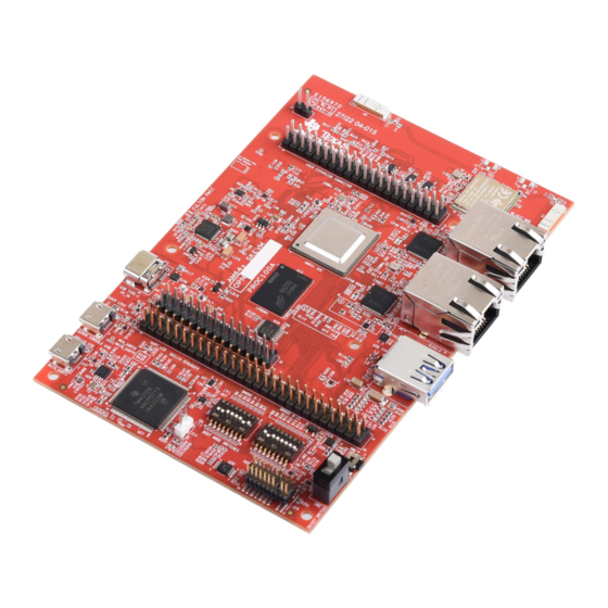
Page 6: System Description
Figure 4-1. Top View of Starter Kit Processor Board Note: Two USB Micro-B Receptacles J12: XDS110 USB TO MAIN UART1 J11: DEBUG CONSOLE (MCU UART0 and MAIN UART1) AM64x SK EVM SPRUIY9B – MAY 2021 – REVISED OCTOBER 2023 Submit Document Feedback Copyright © 2023 Texas Instruments Incorporated... -
Page 7: Key Features
• 512 Kbit Inter-Integrated Circuit (I2C) board ID EEPROM High Speed Interface: • Two CPSW Gigabit Ethernet (RGMII) ports interfaced with Texas Instruments Gigabit Ethernet PHYs SPRUIY9B – MAY 2021 – REVISED OCTOBER 2023 AM64x SK EVM Submit Document Feedback... - Page 8 – Qualtek USB 2.0 Cable C Male to C Male 3.28' Shielded Cable for powering the boards through a laptop Type-C port - 3021091-01M • Status Output: LEDs to indicate power status Compliance: • RoHS Compliant • REACH Compliant AM64x SK EVM SPRUIY9B – MAY 2021 – REVISED OCTOBER 2023 Submit Document Feedback Copyright © 2023 Texas Instruments Incorporated...
-
Page 9: Functional Block Diagram
Figure 4-3 shows the functional block diagram of the AM64x SK EVM. Figure 4-3. Starter Kit Processor Board Functional Block Diagram SPRUIY9B – MAY 2021 – REVISED OCTOBER 2023 AM64x SK EVM Submit Document Feedback Copyright © 2023 Texas Instruments Incorporated... -
Page 10: Power-On/Off Procedures
6. Visually inspect the LEDs against the reference photos below. The following LEDs are illuminated: LD2 and LD16 on top side of the board. AM64x SK EVM SPRUIY9B – MAY 2021 – REVISED OCTOBER 2023 Submit Document Feedback Copyright © 2023 Texas Instruments Incorporated... -
Page 11: Power-Off Procedure
4.4 Peripheral and Major Component Description The following sections provide an overview of the different interfaces and circuits on the AM64x SK EVM. SPRUIY9B – MAY 2021 – REVISED OCTOBER 2023 AM64x SK EVM Submit Document Feedback Copyright © 2023 Texas Instruments Incorporated... -
Page 12: Clocking
MCU_PORz is the power ON/ Cold Reset input for MCU and Main domain. • MCU_RESETz is the warm reset input for MCU domain. AM64x SK EVM SPRUIY9B – MAY 2021 – REVISED OCTOBER 2023 Submit Document Feedback Copyright © 2023 Texas Instruments Incorporated... -
Page 13: Power
3V3 from two different sources. First, 3V3 supply is generated from 5 V (XDS_USB_VBUS) using an LDO (Part No: TPS79601DRBR). This is generated as long as Micro B cable is connected to J12. Second, SPRUIY9B – MAY 2021 – REVISED OCTOBER 2023 AM64x SK EVM Submit Document Feedback Copyright © 2023 Texas Instruments Incorporated... -
Page 14: Usb Type-C Interface For Power Input
Default current in unattached state Default current in attached state Medium current (1.5A) in attached state High current (3.0A) in attached state AM64x SK EVM SPRUIY9B – MAY 2021 – REVISED OCTOBER 2023 Submit Document Feedback Copyright © 2023 Texas Instruments Incorporated... -
Page 15: Power Fault Indication
Points on Bottom Side VCC3V3SYS_EXT TP78 DGND J3.2 VDDA_1V8 TP86 DGND J3.2 VCC3V3_TA C340.1 DGND J3.2 VCC3V3_TA_XDS C421.1 DGND J3.2 SPRUIY9B – MAY 2021 – REVISED OCTOBER 2023 AM64x SK EVM Submit Document Feedback Copyright © 2023 Texas Instruments Incorporated... -
Page 16: Power Sequencing
Power Up and Power Down Sequence of all the Power supplies present on the SK EVM Board. Figure 4-9. Power-Up and Power-Down Sequencing AM64x SK EVM SPRUIY9B – MAY 2021 – REVISED OCTOBER 2023 Submit Document Feedback Copyright © 2023 Texas Instruments Incorporated... -
Page 17: Power Supply
VDDA_TEMP_0/1 VDDA_PLL_0/1/2 VDDS_DDR VDDS_DDR DDR0 VDDS_DDR_C SOC_DVDD1V8 VDDSHV4 FLASH VDDS_MMC0 MMC0 VMON_1P8_MCU VMON_1P8_SOC VDDSHV_SD_IO VDDSHV5 MMC1 VDDS_MMC0/ VDDS_MMC0 MMC0 ADC0_VREFP SPRUIY9B – MAY 2021 – REVISED OCTOBER 2023 AM64x SK EVM Submit Document Feedback Copyright © 2023 Texas Instruments Incorporated... -
Page 18: Configuration
Table 4-7 provide guidance to select the boot mode before the device is powered up. Figure 4-10. Bootmode Switch Positions Example AM64x SK EVM SPRUIY9B – MAY 2021 – REVISED OCTOBER 2023 Submit Document Feedback Copyright © 2023 Texas Instruments Incorporated... -
Page 19: Table 4-7. Boot-Mode Pin Mapping
• BOOT-MODE [10:12] – Select the backup boot mode, that is, the peripheral/memory to boot from, if primary boot device failed. Table 4-10 provides backup boot mode selection details. SPRUIY9B – MAY 2021 – REVISED OCTOBER 2023 AM64x SK EVM Submit Document Feedback Copyright © 2023 Texas Instruments Incorporated... -
Page 20: Table 4-10. Backup Boot Mode Selection Boot-Mode [12:10]
Table 4-12. Backup Boot Media Configuration BOOT-MODE [13] SW2.3 Boot Device Reserved None Mode Reserved Reserved Reserved UART Ethernet Port MMC/SD Reserved Reserved AM64x SK EVM SPRUIY9B – MAY 2021 – REVISED OCTOBER 2023 Submit Document Feedback Copyright © 2023 Texas Instruments Incorporated... -
Page 21: Jtag
USB slave device. The VBUS power from the connector is used to power the SPRUIY9B – MAY 2021 – REVISED OCTOBER 2023 AM64x SK EVM Submit Document Feedback Copyright © 2023 Texas Instruments Incorporated... -
Page 22: Test Automation
The pins used for boot mode also have other functions, which is isolated by disabling the boot mode buffer during normal operation. Figure 4-12 shows the test automation signal connection with AM64x. AM64x SK EVM SPRUIY9B – MAY 2021 – REVISED OCTOBER 2023 Submit Document Feedback Copyright © 2023 Texas Instruments Incorporated... -
Page 23: Figure 4-12. Test Automation Header
Table 4-15. Automation Header Signals Connected to XDS110 TM4C1294 Pin Name Signal Name TEST_POWERDOWN TEST_PORZn TEST_WARMRESETn TEST_GPIO1 TEST_GPIO2 TEST_GPIO3 TEST_GPIO4 TEST_POWERDOWN TEST_PORZn TEST_WARMRESETn SPRUIY9B – MAY 2021 – REVISED OCTOBER 2023 AM64x SK EVM Submit Document Feedback Copyright © 2023 Texas Instruments Incorporated... -
Page 24: Table 4-16. Test Automation Header (J16) Pin-Outs
TEST_GPIO3 Input TEST_GPIO4 Input DGND Ground SOC_I2C1_TA_SCL Bidirectional BOOTMODE_I2C_SCL Bidirectional SOC_I2C1_TA_SDA Bidirectional BOOTMODE_I2C_SDA Bidirectional DGND Ground DGND Ground DGND Ground AM64x SK EVM SPRUIY9B – MAY 2021 – REVISED OCTOBER 2023 Submit Document Feedback Copyright © 2023 Texas Instruments Incorporated... -
Page 25: Uart Interface
±12- kV air-gap Discharge. Figure 4-13 shows the dual UART to USB bridge connection with AM64x. Figure 4-13. UART Interface SPRUIY9B – MAY 2021 – REVISED OCTOBER 2023 AM64x SK EVM Submit Document Feedback Copyright © 2023 Texas Instruments Incorporated... -
Page 26: Memory Interfaces
TVS diodes providing system-level IEC 61000-4-2 ESD protection, ± 8-kV contact discharge and ± 15kV air-gap discharge. AM64x SK EVM SPRUIY9B – MAY 2021 – REVISED OCTOBER 2023 Submit Document Feedback Copyright © 2023 Texas Instruments Incorporated... -
Page 27: Figure 4-15. Micro Sd Interface
AM64x using level translator (SN74AVC4T245RSVR). Input clock is provided by using 32.768 KHz oscillator. Test points are provided on MMC0_DAT [4:7] pins of SOC and WL_GPIO, BT_UART_DEBUG, WL_UART_DEBUG pins on WL1837 Module. SPRUIY9B – MAY 2021 – REVISED OCTOBER 2023 AM64x SK EVM Submit Document Feedback Copyright © 2023 Texas Instruments Incorporated... -
Page 28: Figure 4-16. Wilink Module Interface
Footprints to mount external pull up resistors are provided on DATA [7:0] to prevent bus floating. Figure 4-17 shows the OSPI interface block diagram for AM64x SK EVM. AM64x SK EVM SPRUIY9B – MAY 2021 – REVISED OCTOBER 2023 Submit Document Feedback Copyright © 2023 Texas Instruments Incorporated... -
Page 29: Figure 4-17. Ospi Interface
WP pin is internally pulled down to GND. Here, WP is connected through GND through 10k resistor. Figure 4-18. Board ID EEPROM SPRUIY9B – MAY 2021 – REVISED OCTOBER 2023 AM64x SK EVM Submit Document Feedback Copyright © 2023 Texas Instruments Incorporated... -
Page 30: Ethernet Interface
Mode 4 is not applicable and Mode2, Mode3 option is not desired. Default strap setting of CPSW RGM I 1Ethernet PHY and CPSW RGMII1 Ethernet PHY are given in Table 4-18 Table 4-19. AM64x SK EVM SPRUIY9B – MAY 2021 – REVISED OCTOBER 2023 Submit Document Feedback Copyright © 2023 Texas Instruments Incorporated... -
Page 31: Figure 4-19. Cpsw Ethernet Phy-1 Strap Settings
System Description Figure 4-19. CPSW Ethernet PHY-1 Strap Settings SPRUIY9B – MAY 2021 – REVISED OCTOBER 2023 AM64x SK EVM Submit Document Feedback Copyright © 2023 Texas Instruments Incorporated... -
Page 32: Figure 4-20. Cpsw Ethernet Phy-2 Strap Settings
Function for PRG1 Description PHY Address RX_D2 PHY_AD3 PHY Address: 0000 PHY_AD2 PHY_AD1 RX_D0 PHY_AD0 Auto Negotiation RX_DV/RX_CTRL Auto- neg Auto neg Disable=0 AM64x SK EVM SPRUIY9B – MAY 2021 – REVISED OCTOBER 2023 Submit Document Feedback Copyright © 2023 Texas Instruments Incorporated... -
Page 33: Table 4-19. Default Strap Setting Of Cpsw Rgmii-2 Ethernet Phy
RGMII Clock Skew RGMII RX Clock RX[2] Skew is set to 2 ns RGMII Clock Skew TX[1] GPIO_0 RGMII Clock Skew RX[0] SPRUIY9B – MAY 2021 – REVISED OCTOBER 2023 AM64x SK EVM Submit Document Feedback Copyright © 2023 Texas Instruments Incorporated... -
Page 34: Dp83867 - Power, Clock, Reset, Interrupt And Leds
MHz link and LED2 is connected to RJ45 LED (Yellow) to indicate transmit/receive activity. LED Control is achieved through an external MOSFET. AM64x SK EVM SPRUIY9B – MAY 2021 – REVISED OCTOBER 2023 Submit Document Feedback Copyright © 2023 Texas Instruments Incorporated... -
Page 35: Figure 4-21. Ethernet Interface
System Description Figure 4-21. Ethernet Interface Note Resistors which are highlighted by red color box are DNI components SPRUIY9B – MAY 2021 – REVISED OCTOBER 2023 AM64x SK EVM Submit Document Feedback Copyright © 2023 Texas Instruments Incorporated... -
Page 36: Industrial Application Leds
Data lines shall be provided to take care of EMI/EMC. An ESD protection device of part number TPD4S012 is included to dissipate ESD strikes on USB2.0 DP/DM Signals. Figure 4-23. USB 3.0 Host Interface AM64x SK EVM SPRUIY9B – MAY 2021 – REVISED OCTOBER 2023 Submit Document Feedback Copyright © 2023 Texas Instruments Incorporated... -
Page 37: Pru Connector
PRG0_PRU1GPO0 PRG0_PRU1GPO1 PRG0_PRU1GPO2 PRG0_PRU1GPO3 PRG0_PRU1GPO4 PRG0_PRU1GPO5 PRG0_PRU1GPO6 PRG0_PRU1GPO7 PRG0_PRU1GPO8 PRG0_PRU1GPO9 PRG0_PRU1GPO10 PRG0_PRU1GPO11 PRG0_PRU1GPO12 PRG0_PRU1GPO13 PRG0_PRU1GPO14 PRG0_PRU1GPO15 PRG0_PRU1GPO16 PRG0_PRU1GPO17 DGND VCC3V3_PRU SPRUIY9B – MAY 2021 – REVISED OCTOBER 2023 AM64x SK EVM Submit Document Feedback Copyright © 2023 Texas Instruments Incorporated... -
Page 38: User Expansion Connector
RPI_GPIO0_32 RPI_GPIO0_38 VCC3V3_RPI RPI_GPIO0_39 RPI_SPI0_D0 DGND RPI_SPI0_D1 RPI_GPIO0_40 RPI_SPI0_CLK RPI_SPI0_CS0 DGND RPI_SPI0_CS1 SoC_I2C0_SDA SoC_I2C0_SCL RPI_ETHRPWM5_A DGND RPI_ETHRPWM5_B RPI_ETHRPWM4_A RPI_ETHRPWM4_B DGND AM64x SK EVM SPRUIY9B – MAY 2021 – REVISED OCTOBER 2023 Submit Document Feedback Copyright © 2023 Texas Instruments Incorporated... -
Page 39: Figure 4-25. 40-Pin User Expansion Connector
Table 4-21. 40 Pin User Expansion Connector (continued) Net Name Net Name RPI_SPI1_D1 RPI_SPI1_CS2 RPI_GPIO0_41 RPI_SPI1_D0 RPI_HAT_DETECT RPI_SPI1_CLK Figure 4-25. 40-Pin User Expansion Connector SPRUIY9B – MAY 2021 – REVISED OCTOBER 2023 AM64x SK EVM Submit Document Feedback Copyright © 2023 Texas Instruments Incorporated... -
Page 40: Mcu Connector
MCU_GPIO0_9 DGND MCU_I2C1_SDA MCU_UART1_RTS_3V3 MCU_SPI0_CLK MCU_UART1_TX_3V3 DGND MCU_I2C0_SDA MCU_I2C1_SCL MCU_RESETSTATz MCU_I2C0_SCL CONN_MCU_RESETz MCU_SAFETY_ERRORz_3V3 DGND CONN_MCU_PORz Figure 4-26. 28-Pin MCU Connector AM64x SK EVM SPRUIY9B – MAY 2021 – REVISED OCTOBER 2023 Submit Document Feedback Copyright © 2023 Texas Instruments Incorporated... -
Page 41: Interrupt
SOC I2C (2) Interface: Connected I2C [2] from SoC to the Ra-Pi Expansion Header. Figure 4-27 depicts the I2C tree. Figure 4-27. I2C Interface SPRUIY9B – MAY 2021 – REVISED OCTOBER 2023 AM64x SK EVM Submit Document Feedback Copyright © 2023 Texas Instruments Incorporated... -
Page 42: Io Expander (Gpios)
Power Switch Enable RPI_PS_5V0_En Output User Expansion Connector: 5V0 supply power switch enable RPI_HAT_DETECT Input User expansion connector: hardware add-on board detection AM64x SK EVM SPRUIY9B – MAY 2021 – REVISED OCTOBER 2023 Submit Document Feedback Copyright © 2023 Texas Instruments Incorporated... -
Page 43: Known Issues
For customers desiring an integrated PMIC solution, Texas Instruments is currently developing a PMIC that meets the needs of the AM64x processor family, and are featured on an upcoming AM64x Starter Kit revision. -
Page 44: Issue 4 - Lpddr4 Data Rate Limitation In Stressful Conditions
Solution:Installing 10K resistor on R68, R69, R70, R84, R85 and R466 in the top side of the EVM resolve the issue. AM64x SK EVM SPRUIY9B – MAY 2021 – REVISED OCTOBER 2023 Submit Document Feedback Copyright © 2023 Texas Instruments Incorporated... -
Page 45: Figure 5-1. Mmc1 Schematics
Known Issues Figure 5-1. MMC1 Schematics SPRUIY9B – MAY 2021 – REVISED OCTOBER 2023 AM64x SK EVM Submit Document Feedback Copyright © 2023 Texas Instruments Incorporated... -
Page 46: Figure 5-2. Mmc1 Layout
Known Issues www.ti.com Figure 5-2. MMC1 Layout AM64x SK EVM SPRUIY9B – MAY 2021 – REVISED OCTOBER 2023 Submit Document Feedback Copyright © 2023 Texas Instruments Incorporated... -
Page 47: Regulatory Compliance
Regulatory Compliance 6 Regulatory Compliance Hereby, Texas Instruments declares that the radio equipment, "AM64x Starter Kit for the Sitara Processors" is in compliance with directive 2014/53/EU. The full text of the EU declaration of conformity is available in website. -
Page 48: Revision History
Updated 54-Pin PRU Connector image......................37 • Updated 40-Pin User Expansion Connector image..................38 • Updated 28-Pin MCU Connector image......................• Updated I2C Interface image..........................41 AM64x SK EVM SPRUIY9B – MAY 2021 – REVISED OCTOBER 2023 Submit Document Feedback Copyright © 2023 Texas Instruments Incorporated... - Page 49 STANDARD TERMS FOR EVALUATION MODULES Delivery: TI delivers TI evaluation boards, kits, or modules, including any accompanying demonstration software, components, and/or documentation which may be provided together or separately (collectively, an “EVM” or “EVMs”) to the User (“User”) in accordance with the terms set forth herein.
- Page 50 www.ti.com Regulatory Notices: 3.1 United States 3.1.1 Notice applicable to EVMs not FCC-Approved: FCC NOTICE: This kit is designed to allow product developers to evaluate electronic components, circuitry, or software associated with the kit to determine whether to incorporate such items in a finished product and software developers to write software applications for use with the end product.
- Page 51 www.ti.com Concernant les EVMs avec antennes détachables Conformément à la réglementation d'Industrie Canada, le présent émetteur radio peut fonctionner avec une antenne d'un type et d'un gain maximal (ou inférieur) approuvé pour l'émetteur par Industrie Canada. Dans le but de réduire les risques de brouillage radioélectrique à...
- Page 52 www.ti.com EVM Use Restrictions and Warnings: 4.1 EVMS ARE NOT FOR USE IN FUNCTIONAL SAFETY AND/OR SAFETY CRITICAL EVALUATIONS, INCLUDING BUT NOT LIMITED TO EVALUATIONS OF LIFE SUPPORT APPLICATIONS. 4.2 User must read and apply the user guide and other available documentation provided by TI regarding the EVM prior to handling or using the EVM, including without limitation any warning or restriction notices.
- Page 53 Notwithstanding the foregoing, any judgment may be enforced in any United States or foreign court, and TI may seek injunctive relief in any United States or foreign court. Mailing Address: Texas Instruments, Post Office Box 655303, Dallas, Texas 75265 Copyright © 2023, Texas Instruments Incorporated...
- Page 54 TI products. TI’s provision of these resources does not expand or otherwise alter TI’s applicable warranties or warranty disclaimers for TI products. TI objects to and rejects any additional or different terms you may have proposed. IMPORTANT NOTICE Mailing Address: Texas Instruments, Post Office Box 655303, Dallas, Texas 75265 Copyright © 2023, Texas Instruments Incorporated...
Need help?
Do you have a question about the AM64 SK EVM Series and is the answer not in the manual?
Questions and answers