Table of Contents
Advertisement
Quick Links
www.ti.com
User's Guide
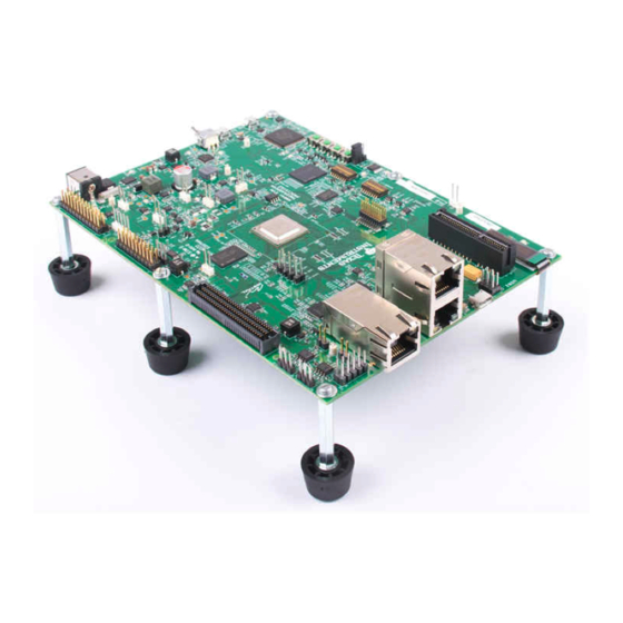
AM64x/AM243x EVM User's Guide
1
Introduction.............................................................................................................................................................................3
1.1 EVM Revisions and Assembly Variants.............................................................................................................................
1.2 Inside the Box....................................................................................................................................................................
Notes...........................................................................................................................................................4
2.1 Power-On Usage Note.......................................................................................................................................................
2.2 EMC, EMI, and ESD compliance.......................................................................................................................................
3 System Description................................................................................................................................................................
Features......................................................................................................................................................................6
3.2 Functional Block Diagram..................................................................................................................................................
3.3 Power-On/Off Procedures..................................................................................................................................................
Procedure...................................................................................................................................................9
3.3.2 Power-Off Procedure.................................................................................................................................................
3.4.1 Clocking.....................................................................................................................................................................
3.4.1.1 Ethernet PHY Clock............................................................................................................................................
3.4.1.2 AM64x/AM243x Clock.........................................................................................................................................
3.4.1.3 PCIe Clock..........................................................................................................................................................
3.4.2 Reset.........................................................................................................................................................................
3.4.3 Power........................................................................................................................................................................
Input.........................................................................................................................................................13
3.4.3.2 Reverse Polarity Protection................................................................................................................................
3.4.3.3 Current Monitoring..............................................................................................................................................
Supply......................................................................................................................................................14
Sequencing..............................................................................................................................................16
3.4.3.6 AM64x/AM243x Power.......................................................................................................................................
3.4.4 Configuration.............................................................................................................................................................
Modes.........................................................................................................................................................18
3.4.5
JTAG..........................................................................................................................................................................22
Automation.........................................................................................................................................................25
3.4.7 UART Interfaces........................................................................................................................................................
Interfaces.....................................................................................................................................................29
3.4.8.1 DDR4 Interface...................................................................................................................................................
Interfaces...................................................................................................................................................30
3.4.8.3 OSPI Interface....................................................................................................................................................
3.4.8.5 Board ID EEPROM Interface..............................................................................................................................
3.4.9 Ethernet Interface......................................................................................................................................................
3.4.9.3 Ethernet LED......................................................................................................................................................
Interface......................................................................................................................................................42
Interface.....................................................................................................................................................43
Interface..........................................................................................................................................................43
3.4.13 High Speed Expansion Interface.............................................................................................................................
3.4.14 CAN Interface..........................................................................................................................................................
3.4.15 Interrupt...................................................................................................................................................................
3.4.16 ADC Interface..........................................................................................................................................................
Connector.....................................................................................................................................................55
3.4.18 SPI Interfaces..........................................................................................................................................................
3.4.19 I2C Interfaces..........................................................................................................................................................
3.4.20 FSI Interface............................................................................................................................................................
SPRUJ63 - SEPTEMBER 2022
Submit Document Feedback
Table of Contents
Description..................................................................................................................11
Interface.......................................................................................................................................32
Configuration..................................................................................................................35
Configuration..................................................................................................................35
Copyright © 2022 Texas Instruments Incorporated
Table of Contents
AM64x/AM243x EVM User's Guide
4
4
4
4
5
8
9
10
11
11
11
11
12
13
13
13
17
18
28
29
31
32
33
41
45
53
54
54
55
55
57
1
Advertisement
Table of Contents


Need help?
Do you have a question about the AM64x and is the answer not in the manual?
Questions and answers