Advertisement
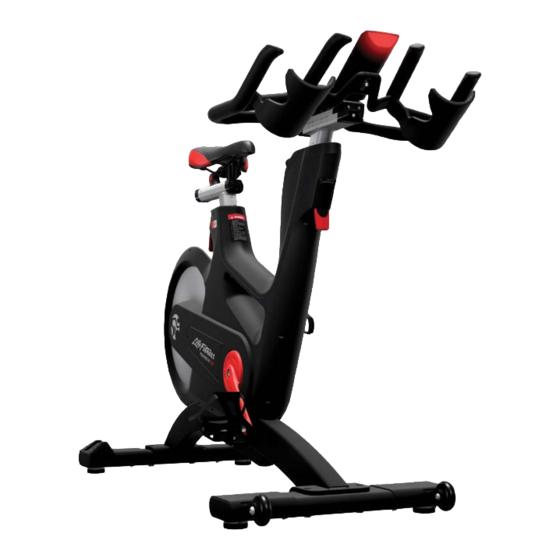
IC7
MODEL NO: IC-LFICGIC7-01
CAUTION!
READ ALL PRECAUTIONS AND INSTRUCTIONS IN THIS MANUAL BEFORE YOU START
USING THIS EQUIPMENT. PLEASE KEEP THIS MANUAL FOR FUTURE REFERENCE.
IMPROPER ASSEMBLY, USE OR MAINTENANCE CAN VOID THE WARRANTY TERMS.
ADDITIONAL LANGUAGES AVAILABLE FOR DOWNLOAD AT WWW.INDOORCYCLING.COM
Version 1.0 2023 IC-LFICGIC7-01 Copyright by Cy-Tech GmbH 2023 | www.indoorcycling.com
MANUFACTURED BY:
Cy-Tech GmbH
Happurger Str. 86
90482 NUERNBERG | Germany
info@indoorcycling.com
www.indoorcycling.com
Phone: +49(0)911 / 54 44 50
Advertisement

Subscribe to Our Youtube Channel
Related Manuals for LifeFitness IC7


Summary of Contents for LifeFitness IC7
- Page 1 MANUFACTURED BY: Cy-Tech GmbH Happurger Str. 86 90482 NUERNBERG | Germany info@indoorcycling.com www.indoorcycling.com Phone: +49(0)911 / 54 44 50 MODEL NO: IC-LFICGIC7-01 CAUTION! READ ALL PRECAUTIONS AND INSTRUCTIONS IN THIS MANUAL BEFORE YOU START USING THIS EQUIPMENT. PLEASE KEEP THIS MANUAL FOR FUTURE REFERENCE. IMPROPER ASSEMBLY, USE OR MAINTENANCE CAN VOID THE WARRANTY TERMS.
- Page 2 ATTENTION Warning labels on the bikes must be replaced by warning labels in your language during the assembly process. Version 1.0 2023 IC-LFICGIC7-01 Copyright by Cy-Tech GmbH 2023 | www.indoorcycling.com...
- Page 3 Um das Handbuch in Ihrer Sprache Du kan laste ned bruksanvisningen herunterzuladen, besuchen Sie bitte på ditt eget språk ved å gå til IC7 den IC7 Support Bereich auf unserer støttesiden på: www.teamicg.com Webseite unter www.teamicg.com Pour télécharger le manuel d‘utilisation Du kan hämta bruksanvisningen på...
-
Page 4: Table Of Contents
P.27 TECHNICAL SPECIFICATIONS: The IC7 Bike is, according to EN ISO 20957-1 and EN ISO 20957-10, a Class S product for use in a controlled environment such as sports or fitness facilities under the supervision of a trainer. WEIGHT OF BIKE:... -
Page 5: Important Precautions
IMPORTANT PRECAUTIONS understand the hazards involved. Children under WARNING! 14 years of age and Persons with reduced physical, To reduce the risk of serious injury due to improper sensory or mental capabilities are prohibited from use of the equipment, carefully read and adhere using the training equipment. -
Page 6: Getting Started
WARNING! You will find the production code for the IC7 Bike on the tag plate which is located on the lower left side of the frame tube of the Indoor Bike. Please enter this production code into care and maintenance lists. -
Page 7: How To Assemble The Indoor Cycle
HOW TO ASSEMBLE THE INDOOR CYCLE TORQUE WRENCH 17MM PEOPLE WARNING! Avoid high fl uctuations in temperature whilst transporting the bike from the store to the installation site. If there are nevertheless large fl uctuations in temperature, please allow the bike to acclimatise to the surrounding temperature before proceeding with assembly. - Page 8 HOW TO ASSEMBLE THE INDOOR CYCLE DO NOT REMOVE THE CARDBOARD WHICH TURN THE THUMB LEVER TO THE LEFT (FIG. A). SLIDE COVERS THE T-NUT. THE CARDBOARD WILL THE HANDLEBAR ON THE STEM. SLIDE OUT DURING INSTALLATION AND GUIDES THE T-NUT FOR EASY INSTALLATION. ALIGN WITH POSITION “0”.
- Page 9 HOW TO ASSEMBLE THE INDOOR CYCLE HAND TIGHT MOUNT THE METAL LIMIT STOP (FIG. A) AND THE PLUG IN BOTH CABLES. POSITION THE CABLE PLASTIC CAP (FIG. B) WITH A 3 MM HEX KEY. INTO THE SLOT (FIG. A). FOLD THE CABLES SO THEY FIT INTO POSITION (FIG.
- Page 10 HOW TO ASSEMBLE THE INDOOR CYCLE CHECK THE VERTICAL ADJUSTMENT, WITH THE FLIP LEVER OPENED, FOR EASE OF MOTION WHEN ADJUSTING. CHECK THE CLAMPING FORCE OF THE VERTICAL ADJUSTMENT WITH THE FLIP LEVER CLOSED. MAKE SURE THE VERTICAL ADJUSTMENT PERFORMS SUFFICIENTLY. ADJUST IF REQUIRED REFERING TO SERVICE GUIDELINES ON AVAILABLE ON MANUFACTURER‘S SERVICE WEBSITE OR CONTACT YOUR LOCAL DISTRIBUTOR.
- Page 11 HOW TO ASSEMBLE THE INDOOR CYCLE REMOVE 2 SCREWS WITH A PHILIPS SCREWDRIVER 55 NM AND DETACH THE PANEL WITH THE BATTERY. OBSERVE ASSEMBLY CONNECT THE INSTRUCTIONS! WIRES MARKED LIPO TOGETHER WARNING! AND REASSEMBLE THE PANEL. Attach the pedal marked R on the right crank and tighten by turning clockwise (standard right- hand thread).
- Page 12 INSTALLATION AND DISPOSING OF BATTERIES Instructions stated in this manual must be performed during initial installation of the ICG Indoor Cycle in order to ensure optimal performance and a long lifespan. Please read and follow the following instructions carefully. If the Indoor Cycles are not installed and configured as described, the components may be subjected to excessive wear and tear and the bike may become damaged.
- Page 13 INSTALLATION AND DISPOSING OF BATTERIES CUSTOMER SERVICE 1. Provide the customer with basic maintenance instructions, and direct them to detailed maintenance instructions. 2. Have the sign-off sheet for the manual, explanation of maintenance procedures and verifi cation of impeccable condition of the bikes confi rmed by the customer when handing over the goods.
-
Page 14: How To Adjust The Indoor Cycle
HOW TO ADJUST THE INDOOR CYCLE The ICG Indoor Cycle can be very easily adjusted, depending on the requirements of various user groups. This enables maximum riding comfort to be ensured whilst achieving optimal training results. The configurations described in the following paragraphs demonstrate just a few of the most often used adjustment variations of which the Indoor Cycle is capable. - Page 15 HOW TO ADJUST THE INDOOR CYCLE ADJUSTING THE SADDLE HORIZONTALLY: Properly positioning the saddle horizontally is very important in order to avoid injury to the knees. Sit on the saddle and move the pedals until the crank arms are in the horizontal position. The knee of your forward-facing leg should be positioned directly above the centre of the pedal.
- Page 16 HOW TO ADJUST THE INDOOR CYCLE HANDLEBAR POSITIONING: Begin with the top of the handlebars at approximately the same height as the saddle (dotted horizontal line A in the drawing below) for inexperienced users set to the “0“ marking (see dotted vertical line B in the drawing below).
-
Page 17: How To Operate The Indoor Cycle
POWER training and QUICKSTART mode. To learn more about the Pedal Effi ciency, go to www.teamicg.com and click on IC7. Left and Right combined... - Page 18 HOW TO OPERATE THE INDOOR CYCLE RESISTANCE KNOB (TURN RESISTANCE ADJUSTMENT KNOB) EMERGENCY BRAKE (PRESS RESISTANCE ADJUSTMENT KNOB) For safety reasons, please always make sure you pedal in a controlled manner and adjust your pedalling frequency to your own cycling capabilities. MOVING THE INDOOR CYCLE: It is recommended that two people move the Indoor Cycle.
- Page 19 HOW TO OPERATE THE INDOOR CYCLE Check the stability of the Indoor Cycle where it is to be operated and if necessary adjust the levelling feet underneath the front or rear stabilizers to ensure the desired stability. IMPORTANT! Please do not unscrew the levelling feet more than 1 cm! The free standing Indoor cycle shall only be installed and operated on a stable and leveled fl oor.
-
Page 20: Preventive Maintenance
PREVENTIVE MAINTENANCE WARNING! Please carefully observe the following instructions. The maintenance and care procedures must be performed in the regularity set out, to ensure maximum operating safety and lifespan. Irregularly observed maintenance and care procedures will lead to increased wear to the product and will void the warranty. - Page 21 PREVENTIVE MAINTENANCE BI-WEEKLY MAINTENANCE: 1. Emergency brake: To ensure operating safety, the emergency brake must be regularly checked to make sure it is functioning properly. To do this, press down the red emergency brake handle whilst pedalling. When functioning optimally, it should produce an immediate braking eff ect and bring the fl ywheel to a complete standstill.
- Page 22 PREVENTIVE MAINTENANCE 3. Handlebars: To maintain the easy adjustment of the handlebar posts, the vertical and horizontal handlebar posts must be regularly cleaned and lubricated. To do this, position the handlebars (A) in the uppermost position, spray the handlebar posts with maintenance spray and rub down the entire exterior surfaces including the horizontal post with a soft cloth.
- Page 23 PREVENTIVE MAINTENANCE USER-DEFINED MAINTENANCE: 1. Vertically adjusting the handlebars and saddle: To ensure the easy adjustment of the vertical handlebar and saddle posts, it is recommended that you check the clamping mechanism and if necessary apply a small amount of lithium/silicone grease to the vertical clamping mechanism of the handlebar posts (1) and saddle posts (2/3).
- Page 24 MAINTENANCE ACTIVITY AND REQUIRED SCHEDULE ACTIVITY ACTIVITY ROTATION ROTATION DETAILS DETAILS FEET LEVELLING, DISINFECTION & CLEANING OF THE BIKE DAILY P 19-20 DETAILED CLEANING OF THE ENTIRE BIKE WEEKLY P 20 CHECK EMERGENCY BRAKE FUNCTION BI-WEEKLY P 21 CLEAN AND LUBRICATE SADDLE &...
- Page 25 MAINTENANCE ACTIVITY AND REQUIRED SCHEDULE BI-WEEKLY MAINTENANCE CHECKLIST BIKE NO. BIKE NO. PRODUCTION CODE OBSERVATIONS ACTION TAKEN RESULT NAME / DATE MONTHLY MAINTENANCE CHECKLIST BIKE NO. BIKE NO. PRODUCTION CODE OBSERVATIONS ACTION TAKEN RESULT NAME / DATE...
-
Page 26: Spare Parts
SPARE PARTS Due to revisions, spare part order no. and specifications may be subject to change. For further information please contact your local distributor or visit www.indoorcycling.com. DESCRIPTION ITEM NUMBER WATTRATE TFT DISPLAY 320-00-00016-01 HANDLEBAR ASSEMBLY 110-01-00114-01 SADDLE 120-01-00076-01 1 PCS.FRONT STABILZER 140-02-00003-01 1 PCS. -
Page 27: Warranty
WARRANTY ICG warrants that all new equipment will be free of manufacturing defects in workmanship and materials, eff ective on the date of original assembly at its production facility. Parts repaired or replaced under the terms of this warranty will be warranted for the remainder of the original warranty period only. ICG is obligated to uphold its manufacturer warranty obligation so long as the product is used in the closed environment it was designed for, Temperature range between 15ºC~40°C Celsius (59ºF~104°F) and max. - Page 28 CAUTION. READ ALL PRECAUTIONS AND INSTRUCTIONS IN THIS MANUAL BEFORE YOU BEGIN USING THIS EQUIPMENT. PLEASE KEEP THIS MANUAL FOR FUTURE REFERENCE. IMPROPER ASSEMBLY, SET UP, USE OR MAINTENANCE MAY VOID THE WARRANTY. EMAIL: INFO@INDOORCYCLING.COM WEBSITE: WWW.INDOORCYCLING.COM © 2021 Cy-Tech GmbH Manufactured by: Cy-Tech GmbH Happurger Str.
Need help?
Do you have a question about the IC7 and is the answer not in the manual?
Questions and answers