LifeFitness LIFECYCLE Owner's Manual
Smart series
Hide thumbs
Also See for LIFECYCLE:
- Assembly instructions manual (117 pages) ,
- Assembly instructions manual (22 pages)
Advertisement
Table of Contents
- 1 Table of Contents
- 2 Important Safety Instructions
- 3 Smart Series Upright Lifecycle ® Exercise Bike Overview
- 4 Assembly
- 5 Initial Setup
- 6 Main Features
- 7 Smart Console Overview
- 8 How to Use the Smart Console
- 9 Workouts, Workout Selection Buttons, & Settings
- 10 Virtual Trainer
- 11 Service and Product Maintenance
- 12 Specifications
- 13 Warranty Information
- Download this manual
Advertisement
Table of Contents

Related Manuals for LifeFitness LIFECYCLE


Summary of Contents for LifeFitness LIFECYCLE
- Page 1 SMART SERIES UPRIGHT LIFECYCLE® EXERCISE BIKE Owner’s Manual 9045401 REV B-2...
- Page 2 ORPORATE EADQUARTERS 5100 River Road Schiller Park, Illinois 60176 • U.S.A. 847.288.3300 • FAX: 847.288.3703 Service phone number: 800.351.3737 (toll-free within U.S.A., Canada) Global Website: www.lifefitness.com NTERNATIONAL FFICES Customer Support: 8.30am - 5.00pm (GMT) All Other EMEA countries & MERICAS Distributor Business C-EMEA* Germany &...
- Page 3 FCC Warning - Possible Radio / Television Interference Note: This equipment has been tested and found to comply with the limits for a Class B digital device, pursuant to part 15 of the FCC rules. These limits are designed to provide reasonable protection against harmful interference in a resi- dential installation.
-
Page 4: Table Of Contents
Smart Series Upright Lifecycle ® Exercise Bike Overview ....... . . - Page 5 How to Obtain Product Service section which will provide information on obtaining domestic and international product service. See Specifications in this manual for product specific features. Statement of Purpose: The Life Fitness Lifecycle exercise bike is a machine that simulates the movements of riding a bicycle at various speeds and levels of resistance.
-
Page 6: Important Safety Instructions
• Do not run the power cord on the floor under or along side of the Lifecycle. • Wear shoes with rubber or high-traction soles. Do not use shoes with heels, leather soles, cleats or spikes. Do not use the Lifecycle in bare feet. - Page 7 • Use this product in a well-ventilated area. • Use this product on a solid, level surface. • Make sure that all components are fastened securely. • An appliance should never be left unattended when plugged in. Unplug from outlet when not in use, and before putting on or taking off parts.
-
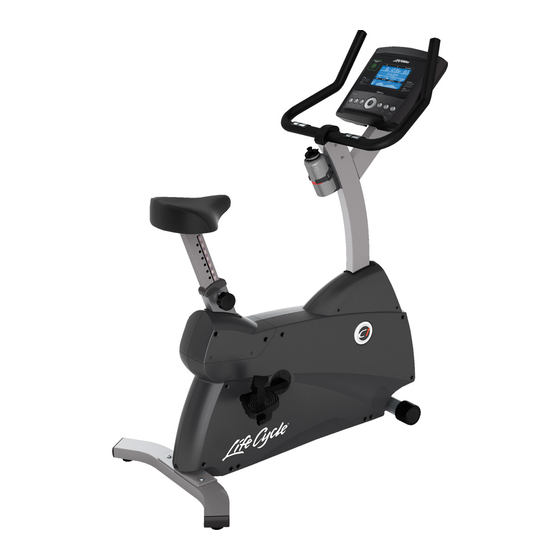
Page 8: Smart Series Upright Lifecycle ® Exercise Bike Overview
® E MART ERIES PRIGHT IFECYCLE XERCISE VERVIEW Contact Heart Rate Sensors Water Bottle Holder Seat Adjustment Pedal Leveler... -
Page 9: Assembly
SSEMBLY & H OOLS ARDWARE Identify the following components after unpacking your Lifecycle. The tools needed for assembly are included. Item Quantity Description 50mm Button Head Screw 20mm Button Head Screw 100mm Hex Head Bolt Thick Flat Washer - 16mm O.D. - Page 10 50mm Button Head Screw 20mm Button Head Screw 100mm Hex Head Bolt 60mm Hex Head Bolt 12mm Self-Tapping Screw Nylock Nut (on seat) Flat Washer (on seat) Thick Flat Washer -16mm O.D. Flat Washer -18mm O.D. Flat Washer -12mm O.D. 15mm Button Head Screw 6mm Phillips Screw with Locking Compound 8mm Phillips Screw...
- Page 11 ACKAGING Parts: None Remove all packaging and place main components to the side of the box. Break box down in each of the four corners. SSEMBLE THE TABILIZER Parts: Hardware Bag #1 (2, 50mm Button Head Screws) (2, 20mm Button Head Screws) Tools: 5mm Hex Head Wrench Locate and install the two LEVELER FEET (A) to the bottom of the REAR STABILIZER (B).With the bends facing rear- ward, attach the REAR STABILIZER (B) to the BASE UNIT (C) using two 50mm BUTTON HEAD SCREWS (1) from the...
- Page 12 ONNECT IRING TTACH OVER Parts: Hardware Bag #3 (4, 12mm Phillips Screws) (4, Flat Washers) Tools: Phillips Screwdriver Detach the WIRE TIE (H) attached to the front of the MONOCOL- UMN (E). Carefully pull the CONSOLE WIRE (L) through the SIDE ACCESS HOLE (M) of the MONOCOLUMN (E).
- Page 13 TTACH ISPLAY ONSOLE Parts: Hardware Bag #5 (2, 8mm Phillips Screws) (4, 12mm Self-Tapping Screws) Tools: Phillips Screwdriver Note: Be careful not to let the CONSOLE WIRE (X) and HEART RATE WIRE (Y) fall into the DISPLAY CONSOLE BRACKET (W). Remove the DISPLAY CONSOLE (AA) from its shipping carton.
- Page 14 SSEMBLE THE ANDLEBAR Parts: Hardware Bag #6 (4, 15mm Button Head Screws) (4, Flat Washers) Tools: 5mm Hex Head Wrench Locate the HANDLEBAR ASSEMBLY (CC). With the handlebars facing forward, position the HANDLEBAR ASSEMBLY near the top of the MONOCOLUMN (E). Connect the WIRES (DD) leading from the HANDLEBAR ASSEMBLY and the MONOCOLUMN.
- Page 15 EDALS Tools: 15mm Open End Wrench Locate the RIGHT PEDAL (EE) (marked with an "R") and PEDAL STRAP (FF) (marked with an "R"). With the side of the PEDAL STRAP marked with an “R” facing upward, slide the slotted end of the PEDAL STRAP through the left slot in the PEDAL.
-
Page 16: Initial Setup
NITIAL ETUP Read the entire User Manual before setting up the Lifecycle exercise bike. HERE TO LACE THE XERCISE Following all safety instructions in Section 1, move the bike to the location in which it will be used. See Section 11, Specifications, for the dimensions of the footprint. - Page 17 OW TO DJUST THE EDAL TRAPS The bike pedal safety straps keep the user's shoes on the pedals during a workout. The straps should fit comfortably, but they also should be tight enough to prevent shoes from slipping at any point in the pedaling rotation. Before working out, the user should test and adjust the tightness of the straps.
-
Page 18: Main Features
EATURES EART ELEMETRY HEST TRAP The console is equipped with a wireless heart rate monitoring system in which electrodes, pressed against the skin, transfer heart rate signals from the user to the console. The electrodes are inside the chest strap (A) that the user wears during the workout. - Page 19 CCESSORIES A Water Bottle Holder (B) is located on the monocolumn of the bike.Additionally, an integrated Reading Rack (C) for sup- porting a book or magazine is located at the base of the console. ONTACT EART The hand pulse sensors (D) are a built-in heart rate monitoring system on the stationary handlebar. During a workout grasp the hand pulse sensors to monitor your heart rate.
- Page 20 ® EART RAINING Research shows that maintaining a specific heart rate while exercising is the optimal way to monitor the intensity of a workout and to achieve maximum results. That is the idea behind the Life Fitness Heart Rate Zone Training® approach to exercise.
-
Page 21: Smart Console Overview
MART ONSOLE VERVIEW Read the entire user manual before setting up your equipment. 1. USB Indicator 2. Message Center 3. iPOD ® Indicator 4. Heart Rate Center 5. Workout Profile Display 6. Results Center: Distance Display and Calorie Display 7. Level Display 8. - Page 22 10. Settings Button 11. Pause / Resume Button 12. Reset Button 13. Virtual Trainer / USB Button 14. Headphone Jack 15. iPod Controls 16. Enter / Start Button 17. Navigation 18. Manual Workout 19. Random Workout 20. Hill Workout 21. Cardio Workout 22.
-
Page 23: How To Use The Smart Console
The USB icon on the left side of the MESSAGE CENTER is displayed whenever a USB drive is plugged in. The USB can execute a workout from www.virtualtrainer.lifefitness.com. See Section 9 for more information on the Life Fitness Virtual Trainer Website. - Page 24 ORKOUT ROFILE ISPLAY The workout profile graphically displays the intensity of a workout with columns of various heights. During the workout the current intensity level the user is in is signified by an arrow located above the appropriate column. During a heart rate workout the workout profile acts like a graph of the user’s heart rate.
- Page 25 7.10 L EVEL ISPLAY Level Display – There are two types of levels used on this product. The first type of level is the actual brake resistance level. This type of level is only adjustable by the user in a manual workout.
- Page 26 The USB port is used to upload goal-based programs and customized workouts from the Life Fitness Virtual Trainer website (www.virtualtrainer.lifefitness.com). Users can also save workout results to the USB and track progress on the website. See Section 9 for more information on the Life Fitness Virtual Trainer website.
- Page 27 7.20 W ORKOUT ELECTION UTTONS Select one of the following workouts by pressing the corresponding button: Manual, Random, Hill, Cardio, Fat Burn, or Fit Test and begin workout set up (see Workout Overviews for a complete description). 7.21 E NERGY AVER UTTON The Energy Saver Mode is used to minimize the power being pulled from the wall when the...
-
Page 28: Workouts, Workout Selection Buttons, & Settings
& S ORKOUTS ORKOUT ELECTION UTTONS ETTINGS ORKOUT VERVIEWS The Smart Console has six pre-programmed workouts that have been developed by Life Fitness. Each workout has a different goal. Read the workout descriptions carefully so that you can develop a workout routine that focuses on reach- ing your specific goals. - Page 29 OW TO SE THE ORKOUTS 1. Manual Workout (Beginner – Just Starting) Access: This workout can be started by pressing the MANUAL workout button. Description: The MANUAL workout is a simple workout that has no pre-defined intensity levels. The MANUAL workout starts the user at level 1 resistance level and at 0.5 MPH.
- Page 30 4. Fat Burn Workout (Beginner – Just Starting) *Chest strap must be worn to execute the workout. Access: This workout can be started by pressing the FAT BURN work- out button. Description: The user must wear a chest strap for this workout to adequately operate.
- Page 31 Very Active L 4-6 men L 5-10 men L 8-14 men Lifecycle L 2-4 women L 3-7 women L 6-10 women After the five-minute FIT TEST is completed, a FIT TEST score and rating will be displayed. Within each suggested...
- Page 32 It is important for you to take the Fit Test under similar circumstances each time. Your heart rate is dependent on many factors, including: • amount of sleep the previous night (at least seven hours is recommended) • time of day •...
- Page 33 OW TO SE THE ETTINGS The Settings menu can be accessed by pressing the SETTINGS key at the “Select Workout” screen. Upon entering the Settings menu, the screen will display “SETTINGS MENU”. • Scroll through the console setting options using the Left/Right arrows. •...
- Page 34 • Software Version – press ENTER to select Console Software Version Console Software Part Number Console Software Build Date • Floor Model – disables Power Save Controls the ability for the product to enter Energy Saver; Floor model ON disables the Energy Saver feature. Selection options are On or Off.
-
Page 35: Virtual Trainer
USB drive. Simply plug in your USB stick to your product and begin your favorite workout instantly. To begin go to www.virtualtrainer.lifefitness.com Download & Save Workouts: Choose one of the following two options to get started: “Create Popular Workouts” or “Create Personalized Workouts”. -
Page 36: Service And Product Maintenance
Cause / Solution Check to see that the power cord is fully plugged into the back of the Lifecycle exercise bike and into the wall. Make sure the power cord is fully seated into the back of the Lifecycle exercise bike. - Page 38 REVENTIVE AINTENANCE The Life Fitness Lifecycle exercise bike is backed by the engineering excellence and reliability of Life Fitness and is one of the most rugged and trouble-free pieces of exercise equipment on the market today. Note: Safety of the equipment can be maintained only if the equipment is examined regularly for damage or wear. Keep the equipment out of use until the defective parts are required or replaced.
- Page 39 10.3 P REVENTIVE AINTENANCE CHEDULE ITEM WEEKLY MONTHLY BI-ANNUALLY Console Overlay Clean Inspect Bottle Holders Clean Inspect Console Mounting Bolts Inspect Frame Clean Inspect Plastic Covers Clean Inspect Inspect Lifepulse Sensors Clean / Inspect Pedals and Straps Clean Inspect 10.4 H BTAIN RODUCT ERVICE...
-
Page 40: Specifications
PECIFICATIONS ITNESS MART ERIES PRIGHT IFECYCLE Designed Use: Home Max User Weight: 300 lbs. / 136 kg Pedal Size: 4.5 in. / 11.5 cm Drive Type: Poly -V belt-drive Power Requirements: 120 Volt (U.S.), 220 Volt (Europe), 240+ Volt (Australia) Accessories: Water Bottle Holder &... -
Page 41: Warranty Information
Manual to assure proper operation and your continued satisfaction. PRODUCT REGISTRATION: Register online at www.lifefitness.com/home/product-registration.html. Our receipt assures that your name, address and date of purchase are on file as a registered owner of the Product. Being a registered owner assures coverage in the... - Page 42 HOW TO GET PARTS & SERVICE: Refer to page one of this manual for your local service contact information. Reference your name, address and the serial number of your Product (consoles and frames may have separate serial numbers). They will tell you how to get a They will tell you how to get a replacement part, or, if necessary, arrange for service where your Product is located.
Need help?
Do you have a question about the LIFECYCLE and is the answer not in the manual?
Questions and answers