
Related Manuals for HORNER RCC972


Summary of Contents for HORNER RCC972
- Page 1 User Manual for RCC Series Controllers RCC972 RCC1410 RCC2414 RCC8842 MAN1078-07-EN_RCC_Series_UM...
-
Page 2: Preface
PREFACE This manual explains how to use the RCC Controller. Copyright© 2017 Horner APG, LLC, 59 South State Avenue, Indianapolis, Indiana 46201.All rights reserved. No part of this publication may be reproduced, transmitted, transcribed, stored in a retrieval system, or translated into any language or computer language, in any form by any means, electronic, mechanical, magnetic, optical, chemical, manual or otherwise, without the prior agreement and written permission of Horner APG, Inc. -
Page 3: Limited Warrantyand Limitation Of Liability
MAN1078-07-EN_RCC_Series_UM LIMITED WARRANTYAND LIMITATION OF LIABILITY Horner APG, LLC, ("HE-APG") warrants to the original purchaser that the RCC controller module manufactured by HE-APG is free from defects in material and workmanship under normal use and service. The obligation of HE-APG under this warranty shall be limited to the repair or... -
Page 4: Visual Map Of Key Chapters
Each RCC unit is sent with a datasheet in the box. The datasheet is the first document to refer to for model-specific information related to RCC models such as pin-outs, jumper settings, and other key installation information. To obtain updates to datasheets, manuals and user documentation, visit a Horner website North America https://hornerautomation.com Europe https://www.hornerautomation.eu... -
Page 5: Table Of Contents
CHAPTER 4: ELECTRICAL INSTALLATION ..................18 Grounding Definition ........................18 Ground Specifications ........................ 18 How to Test for Good Ground ....................19 RCC972 Power Writing ......................20 RCC1410 Power Writing ......................20 RCC2414 Power Writing ......................21 RCC8842 Power Writing ......................21 CHAPTER 5: SERIAL COMMUNICATIONS .................. - Page 6 MAN1078-07-EN_RCC_Series_UM MAC Address ..........................64 Ethernet Module Protocols and Features ................65 Ethernet System Requirements ..................... 65 Ethernet Module Specifications ....................65 Ethernet Module Configuration ....................66 Ethernet Configuration – IP Parameters ................69 Ethernet Module Protocol Configuration ................69 CHAPTER 8: DOWNLOADABLE COMMUNICATION PROTOCOLS ..........
- Page 7 MAN1078-07-EN_RCC_Series_UM 14.1 Overview ............................84 14.2 Settings ............................. 84 14.3 Backup / Restore Data ......................85 14.4 AutoLoad ..........................87 14.5 AutoRun ............................ 89 CHAPTER 15: MAINTENANCE ......................90 15.1 Firmware Updates ........................90 15.2 Backup Battery ........................90 CHAPTER 16: MODBUS COMMUNICATIONS ..................92 16.1 Modbus Overview ........................
-
Page 8: Chapter 1: Safety / Compliance
MAN1078-07-EN_RCC_Series_UM CHAPTER 1: SAFETY / COMPLIANCE Safety Warnings and Guidelines When found on the product, the following symbols specify: Warning – Consult user documentation. Warning – Electrical Shock Hazard. WARNING – EXPLOSION HAZARD – Do not disconnect equipment unless power has been switched off or the area is known to be non-hazardous. -
Page 9: Grounding
Before each use, inspect all cables for breaks or cracks in the insulation. Replace immediately if defective Grounding Grounding is covered in various chapters within this manual. Compliance To check for compliance and updates, visit the Horner website. North America https://hornerautomation.com Europe https://www.hornerautomation.eu... -
Page 10: Chapter 2: Introduction
MAN1078-07-EN_RCC_Series_UM CHAPTER 2: INTRODUCTION General Overview of a 972, 1410, or 8842 RCC Unit Connectors Recessed Buttons -Run/Stop -Load RJ-45 Ports LED Lights -Run -PWR Connectors Figure 02.1 – Overview of the RCC August 6, 2021 Page 10 of 103... -
Page 11: General Overview Of An Rcc2414 Unit
2.2.1 Where to Find Information about the RCC a) Datasheet - The datasheet is the first document to refer to for key information related to specific RCC models. The datasheets are available on the Horner website and contain pin-outs and other model specific information. -
Page 12: Connectivity To The Rcc
MAN1078-07-EN_RCC_Series_UM 2.2.3 Manual Index Major topics of interest may be found in the Index towards the end of this manual. Connectivity to the RCC The RCC has excellent capabilities for connecting to a variety of devices. The diagram below shows some examples of devices that can be used with the RCC. Other Control Other OCS Devices Devices... -
Page 13: Features Of Rcc
MAN1078-07-EN_RCC_Series_UM Features of RCC The RCC are industrial control devices with built in I/O. They combine control, I/O, and networking into a single, integrated package. Unique features of the RCC include: Advanced control capabilities including floating point, multiple auto-tuning PID loops, and string handling capabilities Removable media for storage of programs, data logging, and on-site updating CsCAN networking for communication with remote I/O, other controllers, or PCs... -
Page 14: Useful Documents And References
MAN1078-07-EN_RCC_Series_UM Useful Documents and References Visit our website to obtain user documentation, supplemental documents, certificates, and other documentation. North America https://hornerautomation.com Europe https://www.hornerautomation.eu Opening Cscape Help File After opening the Cscape Help file, either use the Contest, Index or Search tabs to located information. -
Page 15: Chapter 3: Mechanical Installation
NOTE: The datasheet is the first document to refer to for information related to RCC models such as pin-outs, I/O and general specification, and other key installation information. Visit the Horner websites to obtain datasheets, user documentation, and updates. Overview The mechanical installation greatly affects the operation, safety, and appearance of the system. -
Page 16: Rcc Installation
MAN1078-07-EN_RCC_Series_UM RCC Installation These RCC modules are suitable for use in the Class I, Division 2, Groups A, B,C and D Hazardous Locations only. The operating temperature range is -10˚Cto +60˚C. WARNING - EXPLOSION HAZARD - DO NOT DISCONNECT EQUIPMENT UNLESS POWER HAS BEEN SWITCHED OFF OR THE AREA IS KNOWN TO BE NON-HAZRDOUS. - Page 17 MAN1078-07-EN_RCC_Series_UM 3.3.1 Temperature / Ventilation Ensure that the DIN Rail layout design allows for adequate ventilation and maintains the specified ambient temperature range. Consider the impact on the design if operating at the extreme ends of the ambient temperature range. For example, if it is determined that a cooling device is required, allow adequate space and clearances for the device in the panel box or on the panel door if DIN rail is mounted inside.
-
Page 18: Chapter 4: Electrical Installation
CHAPTER 4: ELECTRICAL INSTALLATION NOTE: The datasheet is the first document to refer to for model-specific information related to RCC models for key installation information. Visit the Horner websites to obtain datasheets, user documentation, and updates. Grounding Definition Ground: The term ground is defined as a conductive connection between a circuit or piece of equipment and the earth. -
Page 19: How To Test For Good Ground
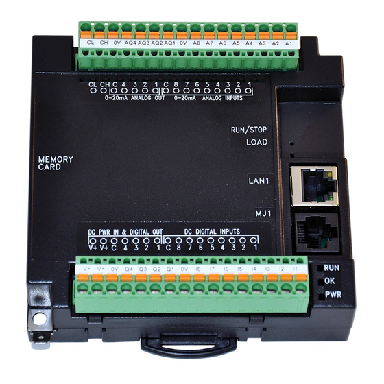
Figure 04.1 – Two-Point Ground Connection Test To power the RCC unit, V+ and V- wires are directly wired to one of the terminal strips, similar to what is shown below on the RCC972. Earth Ground is the auxiliary spade at the bottom. August 6, 2021... -
Page 20: Rcc972 Power Writing
Description DC IN Input power supply positive voltage Input power supply ground To power up the RCC972, supply 10-32VDC to the V+ and C connections on the Power & Input connector. OPTION: Attach ferrite core with a minimum of two turns of the DC+ and DC- signals from the DC supply that is powering the controllers. -
Page 21: Rcc2414 Power Writing
MAN1078-07-EN_RCC_Series_UM RCC2414 Power Writing To power up the RCC2414, supply 20-28VDC to the V+ and V- connections on the Power and Comms Connector. Additionally, a 12 V source is provided at the +12 terminal that is capable of 1 A maximum current. See image below. OPTION: Attach ferrite core with a minimum of two turns of the DC+ and DC- signals from the DC supply that is powering the controllers. - Page 22 MAN1078-07-EN_RCC_Series_UM August 6, 2021 Page 22 of 103...
-
Page 23: Chapter 13: Registers
MAN1078-07-EN_RCC_Series_UM CHAPTER 5: REGISTERS Register Definitions When programming the RCC, data is stored in memory that is segmented into different types. This memory in the controller is referred to as registers. Different groups of registers are defined as either bits or words (16 bits). Multiple registers can usually be used to handle larger storage requirements. -
Page 24: Useful %S And %Sr Registers
MAN1078-07-EN_RCC_Series_UM Useful %S and %SR registers Table 5.2– Common %S Register Definitions Register Description Indicate First Scan Network is OK 10mS timebase 100mS timebase 1 second timebase I/O is OK Always ON Always OFF Pause 'n Load soon %S10 Pause 'n Load done %S11 I/O being forced %S12... - Page 25 MAN1078-07-EN_RCC_Series_UM Table 5.3 – %SR Registers – Master %SR Table Default I/O Min-Max Program Display Register Description Name Values (Read/Write) (Read/Write) %SR4 SELF_TST Self-Test Results Read Only Read Only %SR4.1 Self-Test Results – BIOS Error Read Only Read Only %SR4.2 Self-Test Results –...
- Page 26 MAN1078-07-EN_RCC_Series_UM Table 5.3 – %SR Registers – Master %SR Table Default I/O Min-Max Program Display Register Description Name Values (Read/Write) (Read/Write) Network ID CsCAN Mode 1 to 253 NET_ID %SR29 Read Only Read / Write DeviceNet Mode 0 to 63 CANOpen Mode 1 to 127 Network Baud Rate...
- Page 27 MAN1078-07-EN_RCC_Series_UM Table 5.3 – %SR Registers – Master %SR Table Default I/O Min-Max Program Display Register Description Name Values (Read/Write) (Read/Write) %SR50 RTC_DAY Real-Time-Clock Day (1=Sunday) 1 to 7 Read Only Read Only %SR51 Network Error Count Read Only Read Only %SR52 Watchdog-Tripped Error Count Read Only...
- Page 28 RS-485 Termination Read / Write Read / Write MJ2 Termination Enable %SR152.1 Read / Write Read / Write *Excludes RCC972 MJ3 Termination Enable *XL+ Only %SR152.2 Read / Write Read / Write RS485 Termination Enable * X4 & X7 Only...
- Page 29 MAN1078-07-EN_RCC_Series_UM Table 5.3 – %SR Registers – Master %SR Table Default I/O Min-Max Program Display Register Description Name Values (Read/Write) (Read/Write) MJ1 Termination Enable %SR152.3* Read / Write Read / Write *XL+, XLE, XLT, RCC2414 Only MJ1 Biasing *XL+ Only %SR152.4* Read / Write Read / Write...
- Page 30 MAN1078-07-EN_RCC_Series_UM Table 5.3 – %SR Registers – Master %SR Table Default I/O Min-Max Program Display Register Description Name Values (Read/Write) (Read/Write) *RCC Units Only %SR165-166 Reserved Screen Update Time, Default= 5 %SR167 2 to 50 Read/Write Read/Write *X4 & X7 Only – Default = 10 %SR168-170 Reserved %SR171...
- Page 31 MAN1078-07-EN_RCC_Series_UM Table 5.3 – %SR Registers – Master %SR Table Default I/O Min-Max Program Display Register Description Name Values (Read/Write) (Read/Write) TRUE during first scan of switched- %SR193.5 Read Only Read Only to program TRUE to revert to FLASH and %SR193.6 delete all RAM;...
- Page 32 MAN1078-07-EN_RCC_Series_UM Table 5.3 – %SR Registers – Master %SR Table Default I/O Min-Max Program Display Register Description Name Values (Read/Write) (Read/Write) %SR214 UTC – Hours Read Only Read Only %SR215 UTC – Date Read Only Read Only %SR216 UTC – Month Read Only Read Only %SR217...
-
Page 33: Resource Limits
MAN1078-07-EN_RCC_Series_UM Resource Limits Table 5.4 – Resource Limits Resource Value 192, 200-205 2048 2048 4096 1023 2048 2048 64 (per ID) 64 (per ID) %AIG 32 (per ID) %AQG 32 (per ID) CsCAN, Ping, EGD, SRTP, Modbus TCP Master (Downloadable protocol) & Ethernet Slave, Ethernet IP, FTP, or HTTP @ 10MBd or 100MBd 125kBd, 250kBd,... -
Page 34: Register Map For Rcc Series
Table 5.5—RCC Series Register Map RCC Model REGISTER DESCRIPTION TYPE %I1 to %I8 Digital Inputs %I9 to %I15 Reserved RCC972 %I16 %Q Fault Status %Q1 to %Q4 Digital Outputs %AI1 to %AI8 Analog Inputs 0-20mA %AQ1 to %AQ4 Analog Outputs... -
Page 35: Chapter 11: Cscape Configuration
MAN1078-07-EN_RCC_Series_UM CHAPTER 6: CSCAPE CONFIGURATION Overview RCC hardware is programmed with a Windows based PC application called Cscape. This application can be used to program, configure, monitor and debug all aspects of the RCC unit. Please see the online help provided with Cscape for additional details. Cscape Status Bar When the RCC is connected to a PC using Cscape software, a Status Bar appears at the bottom of the screen. -
Page 36: Establishing Communications
MAN1078-07-EN_RCC_Series_UM Establishing Communications The RCC can communicate with Cscape using serial port communications via MJ1 Port, Ethernet, and CAN (CsCAN). On the RCC2414 model, programming via USB is also available. For RCC, use Cscape Version 9.30 SP6 or later. Connect a PC (Personal Computer running a Windows Microsoft operating system) serial port to the MJ1 port on the RCC. - Page 37 MAN1078-07-EN_RCC_Series_UM The PC will detect a new device has been plugged into the USB port. Now that the RCC is plugged in, go to Cscape → Controller → Connection Wizard. If you are just opening Cscape, Connection Wizard usually opens by default. Select USB and click Next >>.
- Page 38 MAN1078-07-EN_RCC_Series_UM If the Connection Wizard does not pop up upon opening Cscape, then select Controller (in the Cscape tool bar) → Connection Wizard, choose your connection method. If you are connecting for the first time, we suggest connecting via USB. Figure 6.3 –...
- Page 39 MAN1078-07-EN_RCC_Series_UM An alternate way to select the COM setting is to go to Cscape → Tools → Application Settings → Communication and choose the USB port. Figure 6.4 – Cscape: Alternative Connection Method Screenshot Figure 6.5 – Add Target Screenshot in Cscape NOTE: The following fields, Target Name, Connection Medium, Connected Device, and Connection Settings, need to be filled for communication configuration if Cscape Connection Wizard was not used.
- Page 40 NOTE: Cscape will do necessary initialization for the selected internal modem. Select this option to communicate over USB. Now Horner devices and Horner USB to serial converters are recognized and can be specifically selected.
- Page 41 MAN1078-07-EN_RCC_Series_UM If communications are successful, the message line should show “USB (COM8)” for this example, and an (R) should follow the Target number. For more information on the status bar, see the status section above in this chapter, section Cscape Status Bar.
- Page 42 MAN1078-07-EN_RCC_Series_UM 11.3.2 Communicating via On Board Ethernet Port From the factory, the RCC OCS is set to the IP Address 192.168.254.128. To obtain Ethernet communications between Cscape and the RCC OCS using a single Ethernet cable between a PC and the RCC, or through an unmanaged Ethernet Switch, the PC will also need to be manually configured as follows (may require Administrator access on PC): Access the Network Connections in the Control Panel (Shortcut: Press the Windows...
- Page 43 MAN1078-07-EN_RCC_Series_UM August 6, 2021 Page 43 of 103...
- Page 44 MAN1078-07-EN_RCC_Series_UM To configure the Ethernet settings of the RCC using Cscape, go to Controller → Hardware Configuration. If not already done, select the correct connected controller, or use the Auto Config button to automatically recognize a controller that is already successfully connected to Cscape.
-
Page 45: Hardware Configuration
MAN1078-07-EN_RCC_Series_UM Hardware Configuration An overview of configuration: Start the configuration by selecting the Controller → Hardware Configuration menu item. 2. If the RCC is already connected and communicating with Cscape, press the Auto Config System button to automatically detect the connected RCC model. 3. - Page 46 MAN1078-07-EN_RCC_Series_UM Click the Local I/O tab to access the configuration for the I/O. From here, the I/O map and addresses may be viewed. These addresses may not be changed and no other program configurations, such as remote I/O, should overlap these addresses.
- Page 47 MAN1078-07-EN_RCC_Series_UM 7. Configure the Digital Inputs to operate as required. a. If Positive Logic, the inputs will register as ‘ON’ if voltage is applied to the input pin. b. If Negative Logic, the inputs will register as ‘ON’ if the input pin is grounded. 8.
-
Page 48: Scaling Analog Inputs
MAN1078-07-EN_RCC_Series_UM Scaling Analog Inputs To access the Advanced Math Scaling function, select Tools → Project Toolbox. This will open a side bar, and then select Advanced Math → Scale. August 6, 2021 Page 48 of 103... - Page 49 MAN1078-07-EN_RCC_Series_UM Example 1 The Cscape Scale function, found in the Advanced Math functions, allows for very easy conversion of the raw input value into a meaningful reading. For example, a pressure transducer may be specified as a 4-20mA signal to signify a 0-2000 psi pressure reading. With the analog channel set to the 4..20mA range, the raw analog input value, which is in INT format ranges from 0 to 4mA to 32000 for 20mA.
-
Page 50: Chapter 10: General I/O
NOTE: Each RCC unit is sent with a datasheet in the box. The datasheet is the first document to refer to for model-specific information related to RCC models for key installation information. Visit the Horner websites to obtain datasheets, user documentation, and updates. Overview The RCC is a compact unit that contains high density, very versatile I/O. -
Page 51: Digital Inputs
MAN1078-07-EN_RCC_Series_UM Digital Inputs NOTE: The digital inputs on the RCC are designed for low-voltage DC inputs. The inputs are designed to support both positive and negative input modes. The mode is set by a configuration parameter in Cscape. All the inputs on the unit must be configured to the same mode. -
Page 52: Analog Inputs
MAN1078-07-EN_RCC_Series_UM Analog Inputs NOTE: See the data sheet for the RCC model being used and see the appropriate page in this manual (see Index) for details on how to use Cscape to configure the digital filtering. The analog inputs on certain RCC models allow voltage or current measurement from a variety of devices. -
Page 53: Chapter 12: Back-Up Battery
BACK-UP BATTERY The following information pertains to RCC OCS units running 14.24 firmware and later. The RCC972 does NOT have a back-up battery. The RCC1410, RCC2414, and RCC8842 use a 3.7 rechargeable lithium ion battery. The controller will not charge the battery when it is outside. Its charging range is typically - 10°C to 35°C. -
Page 54: Battery Charging Status
MAN1078-07-EN_RCC_Series_UM Battery Charging Status Viewed in the System Menu under “View Battery Status” Waiting The charging system is waiting for voltages and temperatures to stabilize. Battery Charging The battery is charging. Battery Full Shows at the end of a charge cycle. Remains in this state until the battery is steadily discharging. - Page 55 MAN1078-07-EN_RCC_Series_UM August 6, 2021 Page 55 of 103...
-
Page 56: Chapter 5: Serial Communications
Refer to the datasheet specific to the RCC model being used for serial port pinouts. MJ1 Serial Port Pinout NOTE: Please refer to individual datasheets for more details. Table 9.1 – Datasheets for RCC Models RCC Model Datasheet RCC972 MAN0970 RCC1410 MAN1034 RCC2414 MAN1033... - Page 57 MAN1078-07-EN_RCC_Series_UM 9.2.1. RCC972 MJ1 Pins Table 9.2 – RCC 972 MJ1 Pins RCC972 MJ1 Pins Ground (60mA Max) MJ1: RS-232—Use for Cscape programming and application-defined communications. 9.2.2. RCC1410 MJ1 and MJ2 Pins Table 9.3– RCC1410: MJ1 and MJ2 Pins MJ1 Pins...
- Page 58 MAN1078-07-EN_RCC_Series_UM 9.2.3 RCC2414 Serial Port Pins The RCC2414 has two serial ports that are provided via cage clamp terminals. Both are 2-wire RS-485 only. The most common use is for Modbus Communications, either as a Modbus Master or a Modbus Slave. Figure 5.1 –...
-
Page 59: Cscape Programming Via Serial Port
MAN1078-07-EN_RCC_Series_UM Cscape Programming via Serial Port The MJ1 serial port supports CsCAN Programming Protocol (except RCC2414). If a PC COM port is connected to the MJ1 serial port, Cscape can access the RCC for programming and monitoring. Programming can also be done via the CAN connection or Ethernet. For serial port programming on MJ1, HE-XCK Programming Kit can be use (except RCC2414). -
Page 60: Chapter 6: Can Communications
All RCC models provide CAN networking options, which are implemented with CL and CH connections at the terminal. They are similar to the RCC972 shown below. The CAN connection is terminated (120Ω resistor) at each end of the network wiring for proper functionality. -
Page 61: Can Port Wiring
For CAN wiring, use the following wire type or equivalent: Belden 3084, 24 AWG (0.2mm ) or larger. Figure 10.2 – RCC972 CAN Port Wiring 10.3.2 RCC1410 CAN Port Wiring CAN communications are provided via three connectors on the CAN connector: CAN_LOW (CL), CAN_HIGH (CH), and V- (C). - Page 62 MAN1078-07-EN_RCC_Series_UM 10.3.3 RCC2414 CAN Port Wiring The CAN port is provided via three connections on the CAN, Power, and Analog connector: CAN_LOW (CL), CAN_HIGH (CH), and V- (C). If CsCAN expansion I/O is to be used, a 24VDC power source will be required on the CsCAN bus in order to power the expansion I/O modules.
-
Page 63: Cscape Programming Via Can
MAN1078-07-EN_RCC_Series_UM 10.4 Cscape Programming via CAN The CAN port supports CsCAN Programming Protocol. If a PC has a CAN interface installed (via PCI card or USB), and the PC CAN port is connected to the RCC CAN port, Cscape can access the RCC for programming and monitoring. -
Page 64: Chapter 7: Ethernet Communication
MAC Address MAC Address: The RCC MAC Address is found in System Registers %SR35-36. All Horner controllers hold 00-E0 in the first two segments. Therefore, the first two segments of the MAC Address are not represented in System Registers. %SR36 holds the middle two segments of the address. -
Page 65: Ethernet Module Protocols And Features
Ethernet Global Data SRTP Slave (90-30 Service Request Transfer Protocol Service Request) CsCAN TCP Server Horner APG CsCAN over Ethernet (for Cscape to OCS programming) Modbus Slave Modbus over Ethernet Ethernet / IP ODVA CIP over Ethernet FTP (File Server) -
Page 66: Ethernet Module Configuration
MAN1078-07-EN_RCC_Series_UM 11.6 Ethernet Module Configuration NOTE: The following configuration is required for all applications regardless of the protocols used. Additional configuration procedures must be performed for each protocol used. To configure the Ethernet Module, use Cscape Programming Software to perform the following steps: On the main Cscape screen, select the Controller menu and its Hardware Configure sub-menu to open the Hardware Configuration dialog (Figure 11.1). - Page 67 MAN1078-07-EN_RCC_Series_UM Click the Config button to the right of LAN1 revealing the Ethernet Module Configuration dialog as shown in Figure 11.2. Figure 11.2 – Ethernet Module Configuration Configure the Ethernet Module parameters as follows: IP Address: Enter the static IP Address for the Ethernet Module being configured. IP Addresses are entered as four numbers, each ranging from 0 to 255.
- Page 68 MAN1078-07-EN_RCC_Series_UM Table 11.3 - Ethernet Status Word Register Format High Byte Low Byte Dup Spd Link TCP Connections Status Values Status Bit(s) Status Indication Minimum Maximum Reserved Always 0 0 = Half 1 = Full Link Duplex (Auto-Negotiated) Duplex Duplex Link Speed (Auto-Negotiated) 0 = 10MHz 1 = 100MHz...
-
Page 69: Ethernet Configuration - Ip Parameters
MAN1078-07-EN_RCC_Series_UM 11.7 Ethernet Configuration – IP Parameters For primary operation, the IP address, Net Mask, and Gateway should be set in the LAN config of the Cscape Hardware Configuration. There are options to get IP parameters from the LAN Config or to get parameters from registers. The following points on IP parameter configuration should be considered. -
Page 70: Chapter 8: Downloadable Communication Protocols
MAN1078-07-EN_RCC_Series_UM CHAPTER 12: DOWNLOADABLE COMMUNICATION PROTOCOLS 12.1 Overview Through loadable protocol device drivers, certain models of the OCS family can provide the ability to exchange data with remote devices such as variable-frequency drives, PLCs, and remote I/O devices. This feature greatly expands the OCS ’s control capability with negligible effect on the OCS ’s ladder scan time. - Page 71 (automatic) or controlled from ladder logic (manual) once a complex connection is programmatically created (i.e., dialup modem). The specific transaction-scanning mode is selected from the Network Config menu. The following Horner Automation websites offer OCS Protocol Software Downloads. North America http://hornerautomation.com/support-files/ Europe https://www.hornerautomation.eu/support/...
-
Page 72: Protocol Config
MAN1078-07-EN_RCC_Series_UM 12.2 Protocol Config After opening Cscape, choose Program → Protocol Config, and select the port drop-down box to select a protocol device driver. All protocol device drivers currently loaded in Cscape are displayed in the dropdown selection. Some OCS models can be limited in the number of ports or number of protocol device drivers that can be selected. -
Page 73: Network Configuration
MAN1078-07-EN_RCC_Series_UM 11.3 Network Configuration Network Configuration provides the required parameters to configure the network. Each protocol is different and may not require all the Network Config field. Please refer to the table below for the options in the Network Config field. August 6, 2021 Page 73 of 103... - Page 74 MAN1078-07-EN_RCC_Series_UM Table 11.1 – Network Protocols Baud Rate, Data Bits, Stop Bits, These field define the bit level transfer over the serial port. Parity None – No handshake lines are used Handshake Multidrop Full – Rx remains active while Tx is occurring. Multidrop Half –...
-
Page 75: Device List And Device Configuration
MAN1078-07-EN_RCC_Series_UM 12.4 Device List and Device Configuration Device List The Device List is reached from the Device button on the Protocol Config screen and provides a list of the configured devices on the Network. Devices must be created and exist in this list before corresponding Scan List entries can be created for this device. - Page 76 MAN1078-07-EN_RCC_Series_UM Device Configuration This configuration is reached from the Device List when adding or modifying an existing device. August 6, 2021 Page 76 of 103...
-
Page 77: Scan List
MAN1078-07-EN_RCC_Series_UM 12.5 Scan List This can be accessed from the Scan List button on the Protocol Config screen or the Mapping button on the Device List screen and provides a Scan List of the Data Mapping entries. To transfer data between the OCS and remote target, a Scan List must be created that defines each transaction. -
Page 78: Data Mapping Configuration (Scan List Entry)
MAN1078-07-EN_RCC_Series_UM 12.6 Data Mapping Configuration (Scan List Entry) Update Type This field specifies the direction and what triggers the transfer of data between the OCS and target device for a mapping entry. Polled Read On every transaction scan, a read-only target device register(s) transaction occurs. Polled Read/Write On every transaction scan, a read target device register transaction occurs unless a local register value has changed. - Page 79 MAN1078-07-EN_RCC_Series_UM Polled Read/Write/Init On every transaction scan, a read target device register transaction occurs unless a local register value has changed. The write transaction only updates those local registers that have changed in value. If several non-consecutive local registers (contained in a single mapping entry) change value between transaction scans, it takes several consecutive scans to write each changed register.
-
Page 80: Chapter 9: Removable Media
MAN1078-07-EN_RCC_Series_UM CHAPTER 13: REMOVABLE MEDIA 13.1 Overview All RCC models provide a Removable Media slot, labeled Memory Card, which supports standard microSD flash memory cards. microSD cards can be used to save and load applications, to capture graphics screens and to log data for later retrieval. Figure 13.1 –... -
Page 81: Using Removable Media To Log Data
MAN1078-07-EN_RCC_Series_UM 13.4 Using Removable Media to Log Data Using Read and Write Removable Media function blocks, an application ladder program can read and write RCC register data in the form of comma-delimited files, with a .CSV extension. These files are compatible with standard database and spreadsheet PC programs. In addition, an application ladder program can use Rename and Delete Removable Media function blocks to rename and delete files. -
Page 82: Filenames Used With The Removable Media (Rm) Function Blocks
= Year04\Month03\aa01_15.csv Filename: = Month_03\Day_01\15_45_34.csv Month_$M\Day_$D\$h_$m_$s.csv NOTE: Time/Date requires setting on the RCC972 and is only maintained while the RCC is powered. Time and Date will need to be reconfigured on power cycle. August 6, 2021 Page 82 of 103... -
Page 83: System Registers Used With Rm
MAN1078-07-EN_RCC_Series_UM 13.8 System Registers used with RM Table 13.3 – RM System Registers %SR174 Removable Write a 1 to prohibit read/write access to the removable media Media Protect card. Write a zero (0) to allow access. %SR175 Status This shows the current status of the RM interface. %SR176 Free Space This 32-bit register shows the free space on the RM card in bytes. -
Page 84: Chapter 14: Fail-Safe System
MAN1078-07-EN_RCC_Series_UM CHAPTER 14: FAIL-SAFE SYSTEM 14.1 Overview The Fail-Safe System is a set of features that allow an application to continue running in the event of certain types of "soft" failures. These "soft" failures include: • Battery power loss • Battery-Backed Register RAM or Application flash corruption due to, for example, an excessive EMI (Electromagnetic Interference) event. -
Page 85: Backup / Restore Data
MAN1078-07-EN_RCC_Series_UM 14.3 Backup / Restore Data Backup OCS Data: When initiated, this will allow the user to manually copy battery-backed RAM contents on to the onboard flash memory of the OCS. This will have the effect of backing up all the registers and controller settings (Network ID, etc.) that would otherwise be lost due to a battery failure. - Page 86 MAN1078-07-EN_RCC_Series_UM The OCS follows the following sequence in execution of Automatic Restore: OCS Power Cycle Battery Backed RAM Registers check failed Backup exists? Controller placed in Application IDLE mode Program erased Data copied from Onboard FLASH to OCS Battery backed Controller Resets AutoRun OCS put in IDLE...
-
Page 87: Autoload
MAN1078-07-EN_RCC_Series_UM 14.4 AutoLoad This option allows the user to specify whether the OCS automatically loads the application AUTOLOAD.PGM located in Removable Media. When the AutoLoad setting is enabled (set to YES), it can be automatically initiated at power- The automatic initiation will happen only in the following two cases: •... - Page 88 MAN1078-07-EN_RCC_Series_UM The OCS follows the following sequence in execution of AutoLoad: Power up OCS Application Program absent Application Program corrupted AutoLoad OCS put in IDLE mode Enabled? AutoLoad run sequence AUTOLOAD.PGM present in failed (with reasons for the RM of the device ? failure) AutoLoad initiated.
-
Page 89: Autorun
MAN1078-07-EN_RCC_Series_UM 14.5 AutoRun This option, when enabled (YES), allows the user to automatically place the OCS into RUN mode after the AutoLoad operation or automatic Restore Data operation. When the AutoRun setting is disabled (NO), the OCS remains in the IDLE mode after a Restore Data or AutoLoad operation. -
Page 90: Chapter 15: Maintenance
RCC and place in RUN mode. 15.2 Backup Battery All the RCC OCS models, EXCEPT for the RCC972, use a lithium-ion battery. This battery powers the real time clock, registers, and data memory when power is removed. Under normal conditions, the battery should last seven years. - Page 91 MAN1078-07-EN_RCC_Series_UM WARNING: Lithium batteries may explode or catch fire if mistreated. Do NOT recharge, disassemble, heat above 100°C (212°F), incinerate, or puncture. August 6, 2021 Page 91 of 103...
-
Page 92: Chapter 16: Modbus Communications
MAN1078-07-EN_RCC_Series_UM CHAPTER 16: MODBUS COMMUNICATIONS 16.1 Modbus Overview For complete Modbus instructions, please refer to the Help file in Cscape. Modbus (serial) and Modbus TCP/Modbus UDP (Ethernet) are popular, de-facto standard protocols that allow industrial devices from multiple manufacturers to easily share data in real-time. -
Page 93: Modbus Master Overview
Modbus addressing style for each slave on the network, a minimum of address conversion is required. Also, if the slave is another Horner product (i.e. another RCC or an OCS), the “Native Addressing” option can be selected (i.e. %R1, %M17, etc.), and this skips the conversion to Modbus style altogether. -
Page 94: Modbus Addressing Table For Rcc Units
MAN1078-07-EN_RCC_Series_UM 16.4 Modbus Addressing Table for RCC Units To access RCC registers, a Modbus Master must be configured with the appropriate register type and offset. This is usually accomplished with one of two methods: 1. The first method uses Traditional Modbus References, in which the high digit represents the register type and the lower digits represent the register offset (starting with Register 1 for each type). -
Page 95: Chapter 17: Troubleshooting / Technical Support
MAN1078-07-EN_RCC_Series_UM CHAPTER 17: TROUBLESHOOTING / TECHNICAL SUPPORT Chapter 17 provides commonly requested troubleshooting information and checklists for the following topics. Connecting to the RCC controller Local controller and local I/O CsCAN Network Removable media If this information is not enough, please contact Technical Support at the locations indicated at the end of this chapter. -
Page 96: Switch - Normal Functionality
MAN1078-07-EN_RCC_Series_UM 17.3 Switch - Normal Functionality Load switch Used for firmware updated, as noted in previous section Run/Stop switch After boot-up, pressing the RUN/STOP switch for three (3) seconds toggles the RCC between RUN and STOP modes. Switch – Erase Program Function Load and Run/Stop After boot-up, pressing both Load and Run/Stop switches for three (3) seconds performs an “Erase All”... -
Page 97: Connecting To The Rcc
MAN1078-07-EN_RCC_Series_UM 17.5 Connecting to the RCC Cscape connects to the local controller automatically when the serial connection is made. The status bar below shows an example of a successful connection. This status bar is located in the bottom right hand corner of the Cscape window. In general, the Target number should match the Local number. - Page 98 3. Ensure that a cable with proper pinout is being used between PC and controller port MJ1. 4. Check that a Loaded Protocol or ladder is not actively using MJ1. 5. Successful communications with USB-to-serial adapters vary. If in doubt, Horner APG offers a USB to serial adapter. Part numbers HE-XCK and HE-CPK.
-
Page 99: Cscan Network
MAN1078-07-EN_RCC_Series_UM 17.7 CsCAN Network For complete information on setting up a CsCAN network, refer to CAN Networks manual (MAN0799) by visiting the Horner websites for the address to obtain documentation and updates. 17.7.1 CsCAN Network Troubleshooting Checklist Use the proper Belden wire type or equivalent for the network as specified in MAN0799. -
Page 100: Removable Media - Basic Troubleshooting
For manual updates and assistance, contact Technical Support at the following locations: North America: Tel: 1-877-665-5666 Fax: (317) 639-4279 Website: https://hornerautomation.com Email: techsppt@heapg.com Europe: Tel: (+) 353-21-4321-266 Fax: (+353)-21-4321826 Website: https://www.hornerautomation.eu Email: technical.support@horner-apg.com August 6, 2021 Page 100 of 103... -
Page 101: Main Index
MAN1078-07-EN_RCC_Series_UM INDEX Update Type, 41 %Q bits, 47 8.8-System Registers used with RM, 46 Data Mapping Configuration, 41 Accessories, 14 datasheet, 4, 47 Analog Input Tranzorb - Troubleshooting, 49 Default Gateway, 30 Analog Inputs, 49 Device Configuration, 39 Analog Outputs, 49 Device List, 38 AutoLoad, 82 Device List and Device Configuration, 39... - Page 102 Troubleshooting Checklist (Ethernet port RCC1410 MJ1 and MJ2 Pins, 21 Programming), 94 RCC2414 Pins, 22 Troubleshooting Checklist (serial port – MJ1) RCC972 MJ1 Pins, 21 Programming, 94 References / Useful documents, 14 Two-Point Ground Connection Test, 18 Register Map for RCC Series, 78...
-
Page 103: Change Log
MAN1078-07-EN_RCC_Series_UM CHANGE LOG Change Log Date Rev # Description of Revision Location in Doc Added details about supported ethernet Ethernet Overview protocols. (4802) 8/6/2021 Added correct images from datasheets. Throughout August 6, 2021 Page 103 of 103...
Need help?
Do you have a question about the RCC972 and is the answer not in the manual?
Questions and answers