Table of Contents
Advertisement
Quick Links
User Manual
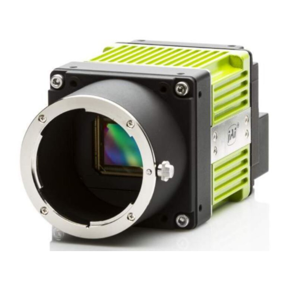
SP-45000M-CXP4
SP-45000C-CXP4
45M CMOS Digital Progressive Scan
Monochrome and color Camera
Document Version: 1.0
SP-45000MC-CXP4_Ver.1.0 _Dec.2019
Thank you for purchasing this product.
Be sure to read this manual before use.
This manual includes important safety precautions and instructions on how to operate the unit. Be sure
to read this manual to ensure proper operation.
The contents of this manual are subject to change without notice for the purpose of improvement.
© 2019 JAI
Advertisement
Table of Contents


Need help?
Do you have a question about the SP-45000M-CXP4 and is the answer not in the manual?
Questions and answers