
Subscribe to Our Youtube Channel
Related Manuals for Unigas RX90


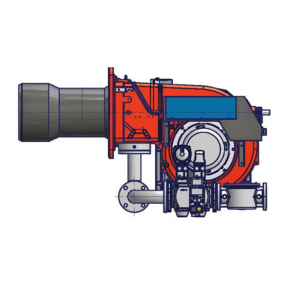
Summary of Contents for Unigas RX90
- Page 1 RX90 - RX91 RX510 - RX515 RX520 Gas burners Low NOx series MANUAL OF INSTALLATION - USE - MAINTENANCE BURNERS - BRUCIATORI - BRULERS - BRENNER - QUEMADORES - ГОРЕЛКИ M039218CD Rel. 3.0 11/2010...
-
Page 2: Table Of Contents
TABLE OF CONTENTS WARNINGS ................................3 PART I: INSTALLATION MANUAL .......................... 5 GENERAL FEATURES ................................... 5 How to interpret the burner’s “Performance curve” ......................... 6 BURNERS FEATURES .................................. 7 Burner model identification ................................7 Technical Specifications ................................. 7 Country and usefulness gas categories ............................8 Overall dimensions .................................. -
Page 3: Warnings
WARNINGS THIS MANUAL IS SUPPLIED AS AN INTEGRAL AND ESSENTIAL PART OF THE PRODUCT AND MUST BE DELIVERED TO THE USER. INFORMATION INCLUDED IN THIS SECTION ARE DEDICATED BOTH TO THE USER AND TO PERSONNEL FOLLOWING PRO- DUCT INSTALLATION AND MAINTENANCE. THE USER WILL FIND FURTHER INFORMATION ABOUT OPERATING AND USE RESTRICTIONS, IN THE SECOND SECTION OF THIS MANUAL. - Page 4 DIRECTIVES AND STANDARDS 3b) FIRING WITH GAS, LIGHT OIL OR OTHER FUELS Gas burners GENERAL European directives: The burner shall be installed by qualified personnel and in com- - Directive 2009/142/EC - Gas Appliances; pliance with regulations and provisions in force; wrong installation Directive 2006/95/EC on low voltage;...
-
Page 5: Part I: Installation Manual
PART I: INSTALLATION MANUAL GENERAL FEATURES Burners of this series represent monobloc burners made in die-cast aluminium housing. The maximum output range is from 2008 to 5800 kW, according to the burner type. They can be provided in progressive or fully-modulating version. Fig. -
Page 6: How To Interpret The Burner's "Performance Curve
How to interpret the burner’s “Performance curve” To check if the burner is suitable for the boiler to which it must be installled, the following parameters are needed: furnace input, in kW or kcal/h (kW = kcal/h / 860); backpressure (data are available on the boiler’s ID plate or in the user’s manual). -
Page 7: Burners Features
Burners are identified by burner type and model. Burner model identification is described as follows. RX510 Type Model (1) BURNER TYPE RX90 - RX91 - RX510 - RX515 - RX520 (2) FUEL M - Natural gas (3) OPERATION (Available versions) PR - Progressive... -
Page 8: Country And Usefulness Gas Categories
RX510 RX515 RX520 BURNER TYPE 800 - 3250 770 - 4400 1000 - 5800 min - max kW Output Natural gas Fuel Category see next paragraph (Stm 85 - 344 81.50 - 466 106 - 614 Gas rate min.-max. min - max mbar Gas pressure see Note 2 400V 3N~ 50Hz... -
Page 9: Overall Dimensions
AD AN AP Omin Omax RX90 1168 35 429 100 290 419 843 422 1294 860 434 228 258 329 360 464 M12 417 295 522 148 374 624 216 649 228 185... - Page 10 O min-max Boiler recommended drilling jig AA AD RX510 1359 1713 1071 642 318 494 540 597 M14 552 390 390 755 150 605 843 216 867 328 270 RX510 1359 1691 1049 642 318 494 540 612 M14 552 390 390 633 150 483 843 292 882 328 270 RX510 1359 1726...
-
Page 11: Performance Curves
Performance Curves RX90 RX91 1000 1400 1800 1200 1600 2000 RX510 RX515 1000 1500 2000 2500 3000 3500 4000 4500 1000 1500 2000 2500 3000 3500 RX520 500 1000 1500 2000 2500 3000 3500 4000 4500 5000 5500 6000 To get the input in kcal/h, multiply value in kW by 860. -
Page 12: Pressure In The Network / Gas Flow Rate Curves
Pressure in the Network / gas flow rate curves RX90 RX91 R p 2" (50) Rp 2" (50) D N 65 DN65 D N 80 DN80 DN100 D N 100 RX510 RX515 Rp 2" (50) Rp 2" (50) DN65 DN65... -
Page 13: Mounting And Connecting The Burner
MOUNTING AND CONNECTING THE BURNER Packing The burners are despatched in wooden crates whose dimensions are: series 9x:1730mm x 1280mm x 1020mm (L x P x H) series 5xx:1730mm x 1430mm x 1130mm (L x P x H) Packing cases of this type are affected by humidity and are not suitable for stacking. The following are placed in each packing case: burner with gas train;... -
Page 14: Matching The Burner To The Boiler
SIDE UP SIDE DOWN RX90-RX91-RX510 Matching the burner to the boiler The burners described in this manual have been tested with combustion chambers that comply with EN676 regulation and whose dimensions are described in the diagram . In case the burner must be coupled with boilers with a combustion chamber smaller in dia- meter or shorter than those described in the diagram, please contact the supplier, to verify that a correct matching is possible, with respect of the application involved. - Page 15 RX515 - RX520 Matching the burner to the boiler The burners described in this manual have been tested with combustion chambers that comply with EN676 regulation and whose dimensions are described in the diagram . In case the burner must be coupled with boilers with a combustion chamber smaller in dia- meter or shorter than those described in the diagram, please contact the supplier, to verify that a correct matching is possible, with respect of the application involved.
-
Page 16: Gas Train Connections
ATTENTION: BEFORE EXECUTING THE CONNECTIONS TO THE GAS PIPE NETWORK, BE SURE THAT THE MANUAL CUTOFF VALVES ARE CLOSED. Burners: RX90-RX91-RX510 Gas train - 1 Gas train with valves group VGD 20/40.. with built-in gas pressure governor + VPS504 gas proving system... - Page 17 Gas train - 4 Gas train with valves group VGD 20/40.. with built-in gas pressure governor + PGCP gas leakage pressure switch INSTALLER MANUFACTURER Gas train - 5 (Rp2) Gas train with valves group MBC 1200SE (2 valves + gas filter + pressure governor) + PGCP gas leakage pressure switch MANUFACTURER INSTALLER Gas train - 6(DN65/80/100)
- Page 18 Burners: RX515-RX520 Gas train - 7 Gas train with valves group VGD 20/40 with built-in gas pressure governor + VPS504 gas proving system MANUFACTURER INSTALLER Gas train - 8 (Rp2) Gas train with valves group MBC 1200SE(2 valves + gas filter + pressure governor) + VPS504 gas proving system MANUFACTURER INSTALLER Gas train - 9 (DN65/80/100)
- Page 19 Gas train - 10: Gas train with valves group VGD 20/40 with built-in gas pressure governor + PGCP MANUFACTURER INSTALLER Gas train - 11 (Rp2): Gas train with valves group VGD 20/40 with built-in gas pressure governor + PGCP MANUFACTURER INSTALLER Gas train 12(DN65/80/100): Gas train with valves group MBC 1900/3100/5000SE (2 valves + gas filter + pressure governor + pressure switch) + PGCP...
-
Page 20: Pilot Gas Train
Pilot gas train (only for RX515/RX520) The pilot gas train is already installed into the burner, the following connections must be carried out: connection from the filter with stabiliser to the gas supply network; connection from valve to the main gas train, by means of the pipe provided with the burner. ... -
Page 21: Assembling The Gas Train
Assembling the gas train To assemble the main gas train, proceed as follows: gas supply network ”direction” arrows for installation Keys 1A..1E Gasket Gas filter Gas valves group Bellows unit Manual valve Fig. 7 - Example for gas train 1-a) in case of threaded joints: use proper seals according to the gas used; 1-b) in case of flanged joints: place a gasket (no. -
Page 22: Siemens Vgd20
Siemens VGD20.. and VGD40.. gas valves - with SKP2.. (pressure governor) Mounting When mounting the VGD.. double gas valve, two flanges are required (as for VGD20.. model, the flanges are threaded); to prevent cuttings from falling inside the valve, first fit the flanges to the piping and then clean the associated parts; ... -
Page 23: Pressure Adjusting Range
MULTIBLOC DUNGS MBC300-700-1200SE (Threaded valves group) Mounting 1. Mount flange onto tube lines. Use appropriate sealing agent (see Fig. 13) 2. Insert MBC...SE. Note position of O rings (see Fig. 14). 3. Tighten screws A – H Fig. 13 4. After installation, perform leakage and functional test. 5. - Page 24 DUNGS MBC valves: Performance range (mbar) 4 - 20 20 - 40 40 - 80 80 - 150 Spring colour black green Siemens VGD valves with SKP actuator : Performance range (mbar) 0 - 22 15 - 120 100 - 250 Spring colour neutral yellow...
-
Page 25: Electrical Connections
ELECTRICAL CONNECTIONS Respect the basic safety rules. make sure of the connection to the earthing system. do not reverse the phase and neutral connections. fit a differential thermal magnet switch adequate for connection to the mains. ATTENTION: before executing the electrical connections, pay attention to turn the plant’s switch to OFF and be sure that the burner’s main switch is in 0 position (OFF) too. - Page 26 Electrical wiring diagram for burners provided with printed circuit (standard configuration). .As far as connections, refer to the terminal block shown on Fig. 18. Fig. 18: Terminal board for connections on printed circuit Connect the signal conductors from the boiler to the burner, as for the next elements (Fig. 19 - Fig. 21): ST: thermostat/pressure switch series TAB: High/low flame thermostat Connect the signal conductors from the burner to the boiler, as for the next elements (Fig.
-
Page 27: Rotation Of Fan Motor
Electrical wiring diagram for burners with no printed circuit provided If the burner is ordered without printed circuit, follow the next connections diagrams. Fig. 22 - Progressive burners Fig. 24 - Fully modulating burners Probes connection by means of the 7-pins plug (Fig. 25) - see Fig. -
Page 28: Adjusting Air And Gas
ADJUSTING AIR AND GAS Combustion head gas pressure curves depending on the flow rate Curves are referred to pressure= 0mbar in the combustion head! The curves referred to the gas pressure in the combustion head, depending on the gas flow rate, are referred to the burner properly adjusted (percentage of residual O in the flues as showed in the “Recommended combustion values”... -
Page 29: Pressure In Combustion Head - Gas Flow Rate Curves
Pressure in combustion head - gas flow rate curves RX90 RX91 RX510 RX515 80 120 160 200 240 280 320 360 400 440 480 RX520... -
Page 30: Adjusting Air And Gas Flow Rates
ADJUSTING AIR AND GAS FLOW RATES Keys 1 Gas filter 3 Gas proving system 4 Gas valves 5 Air pressure switch 6 Adjusting cam 7 Actuator Fig. 27 Gas Filter The gas filters remove the dust particles that are present in the gas, and prevent the elements at risk (e.g.: burners, counters and regu- lators) from becoming rapidly blocked. -
Page 31: Adjusting Air And Gas Flow Rates
Adjusting air and gas flow rates ATTENTION: before starting the burner up, be sure that the manual cutoff valves are open and check that the pres- sure upstream the gas train complies the value quoted on paragraph “Technical specifications”. Be sure that the mains switch is closed. -
Page 32: Air And Gas Flow Rate Settings By Means Of Siemens Sqm40../Berger Stm30.. Actuator
Air and Gas Flow Rate Settings by means of Siemens SQM40../Berger STM30.. actuator mensions Dimensions in SQM4... Actuator cams High flame Stand-by and Ignition Low flame MAN-AUTO MAN-AUTO Berger STM30 Siemens SQM40 check the fan motor rotation (see “Rotation of fan motor” on page 27). Before starting the burner up, drive the high flame actuator microswitch matching the low flame one (in order to let the burner ope- rates at the lowest output) to safely achieve the high flame stage. - Page 33 Dungs MBC..SE Siemens VGD.. To adjust the air flow rate in the high flame stage, loose the RA nut and screw VRA as to get the desired air flow rate: moving the rod TR towards the air damper shaft, the air damper opens and consequently the air flow rate increases, moving it far from the shaft the air damper closes and the air flow rate decreases.
-
Page 34: Adjustment By The Siemens Sql33.. Actuator
Adjustment by the Siemens SQL33.. actuator open the electrical panel to check the fam motor rotation and act directly on the related contactor (see next picture). Turn the burner on by means of its main switch A: if the burner locks (LED B on in the control panel) press the RESET button (C) on the control panel - see chapter “OPERATION”... -
Page 35: Fully Modulating Burners
Note: once the procedure is perfomed, be sure that the blocking nut RA is fasten. Do not change the position of the air damper rods. 10 Only if necessary, change the combusiton head position: see paragraph “Adjusting the combustion head”. 11 the air and gas rate are now adjusted at the maximum output, go on with the point to point adjustment on the SV1 adjusting cam as to reach the minimum output point: gradually move the adjusting cam in order to adjust each of the V1 screws as to set the cam foil shape as described on the next steps:... -
Page 36: Adjusting The Combustion Head
Remeber to fasten V1 and V2 srews. RX90-RX91-RX510: The burner is factory-set with the head in its "all-ahead" position, as for the minimum output. To operate at a ... -
Page 37: Calibration Of Air And Gas Pressure Switches
attached attached RX515 RX520 The smallest holes (pilot holes) are directed towards the flame axis while the biggest ones (main holes) are directed outwards. As for a finest adjustment in the plant, please contact the Technical service. The nozzles can be adjusted as follows: - back and forth adjustment, by means of V1 screws - up and down adjustment, by means of V2 screws Calibration of air and gas pressure switches... - Page 38 Calibration of minimum gas pressure switch As for the gas pressure switch calibration, proceed as follows: Be sure that the filter is clean. Remove the transparent plastic cap. While the burner is operating at the maximum output, test the gas pressure on the pressure port of the minimum gas pressure ...
-
Page 39: Part Ii: Operation
PART II: OPERATION LIMITATIONS OF USE THE BURNER IS AN APPLIANCE DESIGNED AND CONSTRUCTED TO OPERATE ONLY AFTER BEING CORRECTLY CONNEC- TED TO A HEAT GENERATOR (E.G. BOILER, HOT AIR GENERATOR, FURNACE, ETC.), ANY OTHER USE IS TO BE CONSIDE- RED IMPROPER AND THEREFORE DANGEROUS. -
Page 40: Operation
OPERATION BEFORE STARTING UP THE BURNER, BE SURE THAT THE MAIN SWITCH IS ON AND THE MANUAL SHUTOFF VAL- VES ARE OPEN. Turn to the “ON” position the main switch A, on the burner’s control panel (see Fig. 28). Check the control box is not locked (LED B, on) and eventually release it by means of the pushbutton C (reset - for more informa- tion about the device, please refer to the manual’s Appendix). -
Page 41: Part Iii: Maintenance
PART III: MAINTENANCE At least once a year carry out the maintenance operations listed below. In the case of seasonal servicing, it is recommended to carry out the maintenance at the end of each heating season; in the case of continuous operation the maintenance is carried out every 6 months. - Page 42 Removing the combustion head Attention: before adjusting the combustion head, turn the burner off and wait until it gets cold. Remove the cover C. remove the electrodes cables; unscrew the 3 screws V which hold in position the gas manifold G and pull out the complete group as shown in the picture below. ...
-
Page 43: Electrodes Adjustment
RX510: the gap between ignition electrode E and grounded electrode M must be 4mm. RX515-RX520: the electrodes E are placed between the 3rd and the 4th notch of the pilot nozzle U and must match the values (in mm) quoted on Fig. 31. detection electrode RX90-RX91-RX510 RX515-RX520 Fig. 31... -
Page 44: Replacing The Electrodes
“Removing the combustion head”; unscrew VE screws that fasten the electrodes (see next pictures) remove the electrodes and replace them referring to the measures indicated in the previous paragraph; reconnect the electrodes cables; replace the combustion head; replace the burner cover. RX90-RX91-RX510 RX515-RX520... -
Page 45: Cleaning And Replacing The Detection Photocell
Cleaning and replacing the detection photocell (RX515-RX520) To clean/replace the detection photocell, proceed as follows: Disconnect the system from the electrical power supply. Shut off the gas supply remove the photocell from its slot (see next figure); clean the bulbe if dirty, taking care not to touch it with bare hands; if necessary, replace the bulb;... -
Page 46: Replacing The Spring In The Gas Valve Group
Replacing the spring in the gas valve group To replace the spring in the gas valve group,proceed as follows: Carefully twist the protection cap 1 and the O-ring 2. remove the “set value” spring 3 from housing 4. Replace spring 3. Carefully insert the new “set value”... -
Page 47: Troubleshooting
TROUBLESHOOTING TROUBLE CAUSE MAIN SWITCH OPEN LACK OF GAS MAXIMUM GAS PRESSURE SWITCH DEFECTIVE THERMOSTATS/PRESSURE SWITCHES DEFECTIVES OVERLOAD TRIPPED INTERVENTION AUXILIARIES FUSE INTERRUPTED DEFECTIVE CONTROL BOX ... -
Page 48: Burner Exploded View
BURNER EXPLODED VIEW ITEM DESCRIPTION ITEM DESCRIPTION ITEM DESCRIPTION FLANGE 11.12.2 AIR INTAKE DAMPER 13.12 AIR INLET CONE 11.13.1 SPACER 13.13 LEVERAGE INDEX LABEL 11.13.2 SILENCER 13.14 JOINT PRESSURE PLUG 11.13.3 SILENCER 13.15 ACTUATOR SHAFT BUTTERFLY GAS VALVE 12.1 GAS FILTER 13.16 BRACKET BLAST TUBE... -
Page 50: Spare Parts
SPARE PARTS Code Desription RX90 RX91 2020448 2020448 CONTROL BOX DETECTION ELECTRODE 2080106 2080107 IGNITION ELECTRODE 2080269 2080266 2090119 2090119 GAS FILTER - Rp 2” 2090117 2090117 GAS FILTER - DN65 2090112 2090112 GAS FILTER - DN80 2090113 2090113 GAS FILTER - DN100... - Page 51 Desription Code RX510 RX515 RX520 CONTROL BOX 2020448 2020448 2020448 DETECTION ELECTRODE 2080106 IGNITION ELECTRODE 2080269 2080257 2080257 GAS FILTER - Rp 2 2090119 2090119 2090119 GAS FILTER - DN65 2090117 2090117 2090117 GAS FILTER - DN80 2090112 2090112 2090112 GAS FILTER - DN100 2090113 2090113...
-
Page 52: Electrical Wiring Diagrams
ELECTRICAL WIRING DIAGRAMS Wiring Diagrams SE21-018 - RX90 - RX91 - RX510 Wiring Diagrams SE21-015 - RX515 - RX520 ATTENTION: 1- Power supply 400V 50 Hz, 3N a.c. 2- Don’t reverse phase with neutral 3- Ensure burner is properly hearted... -
Page 53: Appendix
APPENDIX consent to start-up by means of the thermostat or pressostat "R" SIEMENS LFL 1.3.. CONTROL BOX start-up program normal burner operation Automatic programme in the event of interruption and indication of posi- tion when interrupted regulation stop caused by "R" By default, in the event of any kind of interruption, the flow of fuel is imme- programmer returns to start-up position A. - Page 54 Ionisation monitor Twin-tube burners (**) voltage in detector electrode Preignition time until the all clear to the pilot burner valve at normal working 330V ±10% terminal 17. test 380V ±10% First safety time (pilot flame strenght); at the end of the safety time short circuit current max.
- Page 55 Programmer diagram pre-ventilation time limit contact switch for damper OPEN position safety time block remote signal '1st safety time main relay (working network) with contacts "ar" pre-ignition time Monitor fuse 'pre-ignition time block relay with "br" contacts interval for creating current between terminals 18 and 19 fuel valve 'interval for creating current between terminals 17 and 19 reset button...
- Page 60 C.I.B. UNIGAS S.p.A. Via L.Galvani, 9 - 35011 Campodarsego (PD) - ITALY Tel. +39 049 9200944 - Fax +39 049 9200945/9201269 web site: www.cibunigas.it - e-mail: cibunigas@cibunigas.it Note: Specifications and and data subject to change. Errors and omissions excepted.
Need help?
Do you have a question about the RX90 and is the answer not in the manual?
Questions and answers