Table of Contents

Subscribe to Our Youtube Channel
Related Manuals for Unigas LAMTEC BT3 Series


Summary of Contents for Unigas LAMTEC BT3 Series
- Page 1 RX92-FGR RX92R-FGR RX512-FGR RX512R-FGR RX515-FGR LAMTEC BT3xx Microprocessor-controlled Gas burners MANUAL OF INSTALLATION - USE - MAINTENANCE BURNERS - BRUCIATORI - BRULERS - BRENNER - QUEMADORES - ГОРЕЛКИ M039486CB Rel 0.0 06/2020...
- Page 2 DANGERS, WARNINGS AND NOTES OF CAUTION THIS MANUAL IS SUPPLIED AS AN INTEGRAL AND ESSENTIAL PART OF THE PRODUCT AND MUST BE DELIVERED TO THE USER. INFORMATION INCLUDED IN THIS SECTION ARE DEDICATED BOTH TO THE USER AND TO PERSONNEL FOLLOWING PRODUCT INSTALLATION AND MAINTENANCE.
- Page 3 3b) FIRING WITH GAS, LIGHT OIL OR OTHER FUELS DIRECTIVES AND STANDARDS Gas burners GENERAL European directives The burner shall be installed by qualified personnel and in compliance -Regulation 2016/426/UE (appliances burning gaseous fuels) with regulations and provisions in force; wrong installation can cause -2014/35/UE (Low Tension Directive) injuries to people and animals, or damage to property, for which the -2014/30/UE (Electromagnetic compatibility Directive)
- Page 4 Burner data plate Type Gas - Light oil burners For the following information, please refer to Model Year European Directives the data plate: S.Number -Regulation 2016/426/UE (appliances burning gaseous fuels) burner type and burner model: must be Output Oil Flow -2014/35/UE (Low Tension Directive) reported in any communication with the Fuel...
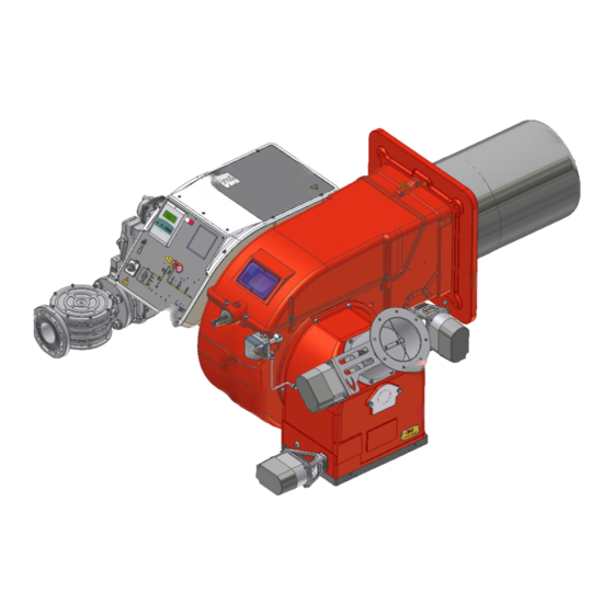
- Page 5 PART I: SPECIFICATIONS PART I: SPECIFICATIONS BURNERS FEATURES Example of burner with FGR Note: the figure is indicative only Control panel with startup switch Gas train Electrical panel Cover Blast tube + Combustion head Flange Air damper Actuator FGR, flue gas recirculation (FGR burners only) 10 Air pressure switch 11 Combustion head adjusting ring nut Gas operation: the gas coming from the supply line, passes through the valves group provided with filter and governor.
- Page 6 PART I: SPECIFICATIONS Burner model identification Burners are identified by burner type and model. Burner model identification is described as follows. Type RX92-FGR Model MD. S. BURNER TYPE RX92-FGR, RX92R-FGR, RX512-FGR, RX512R-FGR, RX515-FGR FUEL M - Natural gas OPERATION (Available versions) MD - Fully modulating BLAST TUBE S - Standard...
- Page 7 PART I: SPECIFICATIONS Technical Specifications RX92-FGR RX92R-FGR RX512-FGR RX512R-FGR RX515-FGR BURNER TYPE M-.. M-.. M-.. M-.. M-.. 680 - 2.504 320 - 1.870 1.280 - 3.600 680 - 2.800 1.065 - 4.160 Output min. - max. kW Fuel M - Natural gas (see next paragraph) Category 72 - 265...
- Page 8 Overall dimensions (mm) - RX92R-FGR, RX92-FGR (AS/AL) (BS/BL) BOILER RECOMMENDED DRILLING TEMPLATE ØXD ØXE FGR FLANGE O min O max BURNER FLANGE 50 1317 1417 135 550 100 390 490 493 868 506 1274 725 439 261 291 228 450 360 464 M12 424 280 310 300 532 148 384 478 481 170 200 549 65 1317 1417 135 564 117 390 490 493 868 506 1520 971 439 261 291 228 447 360 464 M12 424 280 310 300 632 148 484 478...
- Page 9 Overall dimensions (mm) - RX512R - FGR, RX512 - FGR (1.50) 1512 Ø 1555 FGR FLANGE VISTA A BOILER RECOMMENDED BURNER FLANGE DRILLING TEMPLATE...
- Page 10 Overall dimensions (mm) - RX515 - FGR (1.65) 1512 Ø 1577 VISTA A FGR FLANGE BOILER RECOMMENDED BURNER FLANGE DRILLING TEMPLATE...
- Page 11 PART I: SPECIFICATIONS How to read the burner “Performance curve” To check if the burner is suitable for the boiler to which it must be instal- Campo di lavoro bruciatori lled, the following parameters are needed: Tipo P60 Mod. M-xx.x.IT.A.0.50 - M-.xx.x.IT.A.0.65 furnace input, in kW or kcal/h (kW = kcal/h/860);...
- Page 12 PART I: SPECIFICATIONS Performance Curves RX92-FGR RX92R-FGR RX512-FGR RX512R-FGR RX515-FGR To get the input in kcal/h, multiply value in kW by 860. Data are referred to standard conditions: atmospheric pressure at 1013mbar, ambient temperature at 15° C NOTE: The performance curve is a diagram that represents the burner performance in the type approval phase or in the laboratory tests, but does not represent the regulation range of the machine.
- Page 13 PART I: SPECIFICATIONS Pressure in the Network / gas flow rate curves (natural gas) RX92-FGR M-.. RX92R-FGR M-.. RX512-FGR M-.. RX512R-FGR M-.. RX515-FGR M-.. ATTENTION: the gas rate value is quoted on the x-axis, the related network pressure is quoted on the y-axis (pressure value in the combustion chamber is not included).
- Page 14 PART I: SPECIFICATIONS Combustion head gas pressure curves Combustion head gas pressure depends on gas flow and combustion chamber backpressure. When backpressure is subtracted, it depends only on gas flow, provided combustion is properly adjusted, flue gases residual O2 percentage complies with “Recommended combustion values”...
- Page 15 PART I: SPECIFICATIONS Pressure - rate in combustion head curves (natural gas) Curves are referred to pressure = 0 mbar in the combustion chamber! RX92-FGR M-.. RX92R-FGR M-.. RX512-FGR M-.. RX512R-FGR M-.. RX515-FGR M-.. The values in the diagrams refer to natural gas with a calorific value of 8125 kcal/Stm (15°C, 1013 mbar) and a density of 0.714 kg/Stm The values in the diagrams refer to GPL with a calorific value of 22300 kcal/Stm...
- Page 16 PART II: INSTALLATION PART II: INSTALLATION MOUNTING AND CONNECTING THE BURNER Transport and storage ATTENTION! The equipment must be installed in compliance with the regulations in force, following the manufac- turer’s instructions, by qualified personnel. All handling operations must be carried out with appropriate resources and qualified personnel ATTENTION: Use intact and correctly dimensioned hoisting equipment, conforms to the local regulations and health and safety regulations.
- Page 17 PART II: INSTALLATION Fitting the burner to the boiler (RX92R-FGR) To install the burner into the boiler, proceed as follows: make a hole on the closing door of the combustion chamber as described on paragraph “Overall dimensions”) place the burner to the boiler: lift it up and handle it according to the procedure described on paragraph “Handling the burner”; place the 4 stud bolts (5) on boiler’s door, according to the burner drilling template described on paragraph “Overall dimensions”;...
- Page 18 PART II: INSTALLATION Matching the burner to the boiler low NOx burners) The burners described in this manual have been tested with combustion chambers that comply with EN676 regulation and whose dimensions are described in the diagram . In case the burner must be coupled with boilers with a combustion chamber smaller in dia- meter or shorter than those described in the diagram, please contact the supplier, to verify that a correct matching is possible, with respect of the application involved.
- Page 19 PART II: INSTALLATION Sizing of the FGR pipe (FGR burners only) ATTENTION! Performance curve is obtained in a plant designed according to the following guidelines, size the FGR pipe as per the example below. 1111 Keys: 1 Stainless steel FGR pipe, insulated welded to the FGR duct) 2 Burner 5 FGR butterfly valve...
- Page 20 PART II: INSTALLATION GAS TRAIN CONNECTIONS The diagrams show the components of the gas trai included in the delivery and which must be fit- ted by the installer.The diagrams are in compliance with the current laws. Procedure to install the double gas valve unit: - two (2) gas flanges are required;...
- Page 21 PART II: INSTALLATION MultiBloc MBE Actuator VD-V Actuator VD-R Gas filter PS pressure Pressure switch PG min sensor Leakage pressure switch Valve body VB Pressure switch PG max Fig. 7Example of gas train MBE To mount the gas train, proceed as follows: 1-a) in case of threaded joints: use proper seals according to the gas used;...
- Page 22 PART II: INSTALLATION Mounting VD-R & PS-... Actuator VD-R Actuator VD-V 1. Gas pressure regulation is possible with VD-R and PS pressure sensor only. WARNING!!!!. For US/CN installation, the output pressure must be monitoried by min. and max. pressure switches set to +/- 20% of the setpoint. 2.
- Page 23 PART II: INSTALLATION Siemens VGD20.. e VGD40.. Siemens VGD20.. and VGD40.. gas valves - with SKP2.. (pressure governor) - Connect the reference gas pipe (TP in figure; 8mm-external size pipe supplied loose), to the gas pressure nipples placed on the gas pipe, downstream the gas valves: gas pressure must be measured at a distance that must be at least 5 times the pipe size.
- Page 24 PART II: INSTALLATION Integrated proving system burners equipped with BT3x When the burner is switched off, the BT3x device proceeds with an evacuation test, opens the EV1 valve (burner side) and makes sure to bring the test volume (space between EV2 and EV1) to atmospheric pressure. The BT3xx device uses only one pressure switch (PGMIN/LT) mounted between the EV1-EV2 valves which acts as a leak test in the "Gas valve seal"...
- Page 25 PART II: INSTALLATION ELECTRICAL CONNECTIONS WARNING! Respect the basic safety rules. make sure of the connection to the earthing system. do not reverse the phase and neutral connections. fit a differential thermal magnet switch adequate for connection to the mains. WARNING! before executing the electrical connections, pay attention to turn the plant’s switch to OFF and be sure that the burner’s main switch is in 0 position (OFF) too.
- Page 26 PART III: OPERATION PART III: OPERATION LIMITATIONS OF USE THE BURNER IS AN APPLIANCE DESIGNED AND CONSTRUCTED TO OPERATE ONLY AFTER BEING CORRECTLY CONNEC- TED TO A HEAT GENERATOR (E.G. BOILER, HOT AIR GENERATOR, FURNACE, ETC.), ANY OTHER USE IS TO BE CONSIDE- RED IMPROPER AND THEREFORE DANGEROUS.
- Page 27 PART III: OPERATION Fig. 12 - Burner front panel Keys Lock-out LED Hi-flame operation LED Lo-flame operation LED “Ignition transformer operation” LED “Fan motor overload tripped” LED “EV2 opening” LED “EV1 opening” LED “Gas pressure switch signal ” LED Main switch BMS display..
- Page 28 PART III: OPERATION AIR FLOW AND FUEL ADJUSTMENT WARNING! During commissioning operations, do not let the burner operate with insufficient air flow (danger of formation of carbon monoxide); if this should happen, make the fuel decrease slowly until the normal combustion values are achieved.
- Page 29 PART III: OPERATION SETTING THE BURNER CURVE Initial home page: keep thermostat open. Burner Unlock the controller: press ENTER remain in stand-by Info Manual Setting Press the right key to position on the Settings icon (indicated with wrench and hammer) Press ENTER Press ENTER again after selecting 'the key icon'.
- Page 30 PART III: OPERATION Keep the password “0000“ and confirm with ENTER. New page, level 1 unlocked Right click to EDIT. Press ENTER to enter the “curves page”. Air & gas position at burner’s ignition 1 ignition position 2 air servomotor position (digit) 1 gas servomotor position (digit) VALUES VARY FROM BURNER TO BURNER...
- Page 31 PART III: OPERATION Close the thermostat the burner starts. Pre-purge. The controller moves the servomotors to the ignition position and excites the ignition transformer. If the burner starts with those settings, this page will appear: If the burner does not start with those settings the chap- ter "SETTING THE IGNITION POINT WITH BURNER IN STAND-BY”...
- Page 32 PART III: OPERATION Check the lock code & press ENTER to unlock. Press ENTER to modify the positions (burner in stand- Click up to increase the gas opening position or down to decrease it. Clickup to increase the air opening position or down to decrease it.
- Page 33 PART III: OPERATION Press ENTER to save the new settings. CLOSE THE THERMOSTAT LINE BURNER OPERATING: SETTING PARAMETERS Check the combustion quality (with a flue gas analyzer). To modify the combustion valves and adjust servomo- tors position (gas and air), press ENTER. Click up to increase the gas opening position or down to decrease it.
- Page 34 PART III: OPERATION Press ENTER to save the new settings. Click up to quit the ignition position. Check the combustion quality in all positions (from mini- mum to maximum output) and adjust the gas and air setting if necessary (as indicated on chapter “SETTING THE IGNITION POINT WITH BURNER IN STAND?BY”).
- Page 35 PART III: OPERATION Press EXIT again to quit main menu. Press EXIT again to quit settings. The burner runs now in automatic mode. In case of troubles, the burner will go on lock?out mode and thereason will be indicated on the display. Exemple: H009 –...
- Page 36 PART III: OPERATION MultiBloc MBE Regulation VD-R whith PS Setting scale is „Not“ linear! Various sensors available. Output pressure according to sensor‘s measuring range. Increasing pressure Adjust the outlet pressure to the value specified by the burner or equipment manufacturer! Decreasing pressure While making outlet pressure adjustments, do not exceed a value that creates a hazardous condition to the...
- Page 37 PART III: OPERATION Calibration air and gas pressure switches The air pressure switch locks the control box if the air pressure is not the one requested. If it happens, unlock the burner by means of the control box unlock pushbutton, placed on the bur- ner control panel.
- Page 38 PART III: OPERATION Adjusting the combustion head Attention! if it is necessary to change the head position, repeat the air and fuel adjustments described above. .The combustion head position affects the flame stability.The diffuser position must be set during the commissioning according to the regulation needs.
- Page 39 PART IV: MAINTENANCE PART IV: MAINTENANCE At least once a year carry out the maintenance operations listed below. In the case of seasonal servicing, it is recommended to carry out the maintenance at the end of each heating season; in the case of continuous operation the maintenance is carried out every 6 months.
- Page 40 PART IV: MAINTENANCE MultiBloc MBE MultiBloc VD Mounting to push position 1. Position VD on VB, fig. 2+3. 2. Slide VD forward up to the stop, fig. 4. 3. Screw VD on with 2 M5 screws for each, max. 5 Nm/44 in.-lb., fig. 5/6. 4.
- Page 41 PART IV: MAINTENANCE Electrodes Adjustment Important Note: Check the ignition and detection electrodes after removing/adjusting the combustion head. ATTENTION: avoid the ignition and detection electrodes to contact metallic parts (blast tube, head, etc.), other- wise the boiler’s operation would be compromised. Check the electrodes position after any intervention on the combustion head.
- Page 42 PART IV: MAINTENANCE Replacing the ignition electrodes ATTENTION: avoid the ignition and detection electrodes to contact metallic parts (blast tube, head, etc.), otherwise the boi- ler’s operation would be compromised. Check the electrodes position after any intervention on the combustion head. To replace the ignition electrodes, proceed as follows: electrodes - type RX512-FGR, remove the burner cover...
- Page 43 PART IV: MAINTENANCE electrodes - type RX512-FGR, RX512R-FGR To replace the electrodes, proceed as follows: electrodes - type RX92-FGR, RX92R-FGR, RX515R-FGR remove the burner cover C;r disconnect the electrodes cables; emove the combustion head referring to paragraph “Removing the combustion head”; unscrew VE screws that fasten the electrodes (see next pictures) remove the electrodes and replace them referring to the measures indicated in the previous paragraph;...
- Page 44 PART IV: MAINTENANCE TROUBLESHOOTNG GUIDE - Gas operation * No electric power supply * Wait until power supply is back * Main switch open * Close the switch * Thermostats open * Check set points and thermostat connections * Bad thermostat set point or broken thermostat * Set or replace the thermostat * No gas pressure * Restore gas pressure...
- Page 45 PART IV: MAINTENANCE WIRING DIAGRAMS Refer to the attached wiring diagrams. WARNING 1 - Electrical supply 230V / 400V 50Hz 3N a.c. 2 - Do not reverse phase with neutral 3 - Ensure burner is properly earthed...
- Page 46 PART IV: MAINTENANCE...
- Page 48 C.I.B. UNIGAS S.p.A. Via L.Galvani, 9 - 35011 Campodarsego (PD) - ITALY Tel. +39 049 9200944 - Fax +39 049 9200945/9201269 web site: www.cibunigas.it - e-mail: cibunigas@cibunigas.it Note: specifications and data subject to change. Errors and omissions excepted.
- Page 49 Quick Guide LAMTEC BT 3xx SISTEMA DI CONTROLLO ELETTRONICO ELECTRONIC CONTROLSYSTEM SISTEMA DE CONTROL ELECTRÓNICO SYSTÈME DE CONTRÔLE ÉLECTRONIQUE M12929CA 05/2018 ...
-
Page 50: Table Of Contents
1 SUMMARY Summary .................................. 2 OPERATING CONTROL AND DISPLAYS........................ 4 2.1 USER INTERFACE: .......................... 4 2.2 MENU FUNCTIONST: .......................... 4 MAIN MENU ................................ 6 3.1 INFORMATION MENU PATH ...................... 6 3.1.1 INFORMATION PATH: ........................ 6 3.1.2 BURNER DETAILS ........................ 7 3.1.3 Display burner start‐ups ...................... 8 3.1.4 RECALL FAULT HISTORY ...................... 8 3.1.5 SOFTWARE VERSION ........................ 10 3.1.6 DISPLAY OF CHECK SUMS ...................... 10 CRC16 check sums .............................. 10 3.1.7 ... - Page 51 LIST OF FAULT CODES .............................. 27 ASSIGNMENT OF CONFIGURATION FAULT 107 ...................... 30 ASSIGNMENT OF INTERNAL FAULT 999 ........................ 31 SETTING THE BURNER CURVE .......................... 37 SETTING THE IGNITION POINT WITH BURNER IN STAND‐BY ................... 40 SETTING WITH BURNER ON ............................. 42 SETTING OF A NEW CURVE WITH VSD (optional) .................... 45 • This Guide for quick start-up summarises the basic operations that are necessary to start up and set the BT..control unit. The information contained here do NOT replace the user manual and are only intended for qualifie personnel in charge of control unit maintenance.
-
Page 52: Operating Control And Displays
2 OPERATING CONTROL AND DISPLAYS 2.1 USER INTERFACE: Jump to previous window You navigate in the menu using the cursor keys. Enter key: For to confirm the value or operation 2.2 MENU FUNCTIONST: Information Select the INFO path for information about the following: the burner errors that have occurred the software version the serial number actuating drive positions (current damper position for each channel) digital inputs/outputs 4 ... - Page 53 Manual Select the MANUAL to : start and stop the burner manually adjust the internal burner firing‐rate If the burner is switched on manually via display, the BT300 no longer responds to the "Burner ON" signal input at connector X10.2. It is for this reason that the burner will turn off only with the intervention of the “safety chain”, connector X07, which will send it in lock‐out! Settings Select the SETTINGS path for information on, and to make settings or, the following: the password the burner settings (display and settings) the actuator device settings (display) the air/fuel control system the "delete" the display settings 5 ...
-
Page 54: Main Menu
3 MAIN MENU INFORMATION menu path [selected] Display of fuel used Bargraph of internal firing‐rate in % (0 ‐100) MANUAL menu path Access level 2 SETTINGS menu path Window number 3.1 INFORMATION MENU PATH 3.1.1 INFORMATION PATH: Use the cursor keys to select the path and confirm this with Enter Selected burner information [selected] Serial number Fault history Confguration of actual value of actuating outputs (display only) Software version Digital inputs/outputs Check sum display 6 ... -
Page 55: Burner Details
3.1.2 BURNER DETAILS Use the cursor keys to select the path and confirm this with Enter The display shows the "System Information" menu window. For display of operating hours [selected] Number of burner start‐ups Use the cursor keys to select the path and confirm this with Enter The display shows the "Display operating hours" menu window. Pictogram operating hours Total number of operating hours (device connected to mains voltage) Number of operating hours, oil operation Number of operating hours, gas operation 7 ... -
Page 56: Display Burner Start-Ups
3.1.3 DISPLAY BURNER START‐UPS Use the cursor keys to select the path and confirm this with Enter The display shows the "Start‐up counter" menu window Pictogram burner start‐up Number of burner start‐ups, oil operation Number of burner start‐ups, gas operation 3.1.4 RECALL FAULT HISTORY From the home screen, use the cursor keys to select the path and confirm with Enter Use again the cursor keys to select the path and confirm this with Enter Fault history selection menu 8 ... - Page 57 Use the cursor keys to select the path and confirm this with Enter Error code‐display pictogram Fault code (the last 10 faults are stored, in which no. 01 is the most recent fault) Diagnostic code 1 Diagnostic code 2 Number of operating hours at the moment, the fault occurs 9 ...
-
Page 58: Software Version
3.1.5 SOFTWARE VERSION Use the cursor keys to select the path and confirm this with Enter Software version pictogram UI300 software version (user interface) BT3xx software version (BurnerTronic) 3.1.6 DISPLAY OF CHECK SUMS Use the cursor keys to select the path and confirm this with Enter Check sums pictogram Check sum, access level 0 Check sum, access level 1 Check sum, access level 2 Check sum, access level 4 CRC16 CHECK SUMS The check sums are formed from the device parameters. In each case, the BT3xx calculates a check sum for the parameters from access levels 0, 1, 2 and 4. This is displayed as a hex‐adecimal value. The check sums are used to determine whether or not the value for one or more parameters present in the corresponding access level has been changed. 10 ... -
Page 59: Serial Number
3.1.7 SERIAL NUMBER (device BT3xx and display UI300) Use the cursor keys to select the path and confirm this with Enter Serial number pictogram User interface serial number UI300 BurnerTronic serial number BT3xx 3.1.8 DISPLAY POSITIONS OF ACTUATING DRIVES From main page (see paragraf 2.4) use the cursor keys to select the path and confirm this with Enter GAS OFF AIR Actuating drive pictogram Actuating drive channel 1 (air) Actuating drive channel 2 (combustible) Actuating drive channel 3 (off, air, FGR actuator) Optional channel OFF; control of frequency converter Actuatuing drive’s actual position The assignment of the channels is depending on the configuration! 11 ... -
Page 60: Check Digital Inputs/Outputs
3.1.9 CHECK DIGITAL INPUTS/OUTPUTS From main page (see chapter 3) use the cursor keys to select the path and confirm this with Enter Digital inputs pictogram [selected] Digital outputs pictogram Select the menu and confirm this with Enter Page 1 of inputs menu Digital inputs pictogram Jump to next page Fuel selection oil [no] Fuel selection gas [yes] Burner start [yes] – terminal X10 The signals in points 3 and 4, “Page 1 input menu”, are "logical" signals and not "physical". Background: some signals may have more than one source (terminal, LSB, field buses, parameters). 12 ... - Page 61 Use the cursor key to select the next page and confirm this with Enter Page 2 of inputs Digital inputs pictogram Jump to next page Oil pressure min present [no] – terminal X05 Gas pressure min present [yes] – terminal X05 Air pressure min present [yes] – terminal X08 Use the cursor key to select the next page and confirm this with Enter Page 3 of inputs Digital inputs pictogram Jump to previous page Jump to next page Safety interlock chain oil closed [no] – terminal X06 Safety interlock chain gas closed [no] Safety interlock chain boiler closed [no] The signals in points 4 and 5 in Page 2 of inputs menu are "logical" signals, not "physical". The BT3xx supports either oil or gas operation, but cannot be switched. There‐fore there are no separate signals for the oil or gas safety interlock chain. The signal on terminal X06 is thus generally known as "safety interlock chain burner". 13 ...
-
Page 62: Digital Outputs
Use the cursor key to select the next page and confirm this with Enter Page 4 of inputs Digital inputs pictogram Jump to previous page Flame signal present [no] – terminal X21 Fault release [no] – terminal X10 3.1.10 DIGITAL OUTPUTS From previous page (see chapter 3) use the cursor keys to select and confirm this with Enter Page 1 digital outputs Digital outputs pictogram Jump to next page Fan [on] – terminal X25 Error [off] – terminal X24 (adjustable with P 809) Ignition transformer [off] – terminal X04 Use the cursor key to select the next page and confirm this with Enter Page 2 digital outputs Digital outputs pictogram Jump to previous page Jump to next page Oil valve 1 [on] – terminal X01 Oil valve 2 [off] – terminal X02 Oil valve 3 [off] – terminal X03 14 ... - Page 63 Use the cursor key to select the next page and confirm this with Enter Page 3 digital outputs Digital outputs pictogram Jump to previous page Jump to next page Ignition valve [on] – terminal X03 Gas valve 1 [off] – terminal X01 Gas valve 2 [off] – terminal X02 Use the cursor key to select the next page and confirm this with Enter Page 4 digital outputs Digital outputs pictogram Jump to previous page Oil pump [off] – terminal X26 Fuel selection oil [off] – terminal X24 (adjustable with P 809) Fuel selection gas [off] – terminal X24 (adjustable with P 809) 15 ...
-
Page 64: Manual Menu Path
3.2 MANUAL MENU PATH From previous page (see chapter 3) use the cursor keys to select and confirm this with Enter Pictogram Manual Start burner manually [off] Adjust burner manual output Pictogram confirm settings The "Burner ON" control loop does not need to be switched on to start the burner from this menu. The user interface assumes control in this menu. If there is no contact with "Burner ON" signal from other sources (terminal X10.2), the software switches off the burner when you exit the menu. If the burner is switched on manually via display, the BT300 no longer responds to the "Burner ON" signal input at connector X10.2. It is for this reason that limiters, monitors and other similar safety functions must not be used with this input! Leaving the window terminates burner operation! 3.2.1 REGOLAZIONE MANUALE % CARICO BRUCIATORE Use the cursor keys to select the adjustment of the burner firing‐rate in % and confirm this selection with Enter Please note, that you can adjust the burner firing‐rate only while burner is running. Start the burner before you adjust the burner firing‐rate as mentioned above. 16 ... -
Page 65: Settings Menu Path
3.3 SETTINGS MENU PATH From previous page (see chapter 3) use the cursor keys to select and confirm this with Enter Password pictogram (selected) Delete curves Display program settings Setting modulating controller (module LCM100) Read out actuating outputs configuratio Password settings Curve settings Display settings 3.3.1 ENTER PASSWORD Warning: Password level 0 = setting view Password level 1 = change curve points Password level 2 = changing burner parameter settings (pre‐purge, gas leakage, burner parameter, PID, etc.) Use the cursor keys to select and confirm this with Enter Password pictogram (selected) Enter password Access level 2 displayed with access authorisation or acces level 1 with access authorisation depending of the phases Use the cursor keys to select the password fiel you wish to change. b. Change the number with the cursor keys Confirm the password with Enter 17 ... -
Page 66: Program Sequence
3.3.2 PROGRAM SEQUENCE Use the cursor keys to select and confirm this with Enter Duration of pre‐purge [selected] Pilot burner oil operation Duration of post‐purge Valve gas leakage test Pilot burner gas operation SET DURATION OF PRE‐PURGE Use the cursor keys to select and confirm this with Enter Duration of pre‐purge pictogram Pre‐purge time set Accept value by pressing Enter The countdown starts for to confirm the writing value beetwen the display UI300 and burner tronic BT3xx. UI300 pictogram BT3xx pictogram Cancel (back) Parameter number UI300 Parameter number BT300 Transfer by pressing Enter (flashing) Value for UI300 Value for BT300 18 ... - Page 67 Do not accept the value until the values for UI300 and BT300 are the same! The value for the parameter has to be confirmed by pressing Enter in the space of the count‐down (8s)! a‐ Confirm the entry in time by pressing Enter. The value is accepted. The display shows the following page: Display after successfully transferred data UI300 pictogram BT3xx pictogram Parameter number UI300 Parameter number BT300 Pictogram discard parameters Value for BT300 Value for UI300 If both values are equivalent, the value can be accepted by pressing Enter. If there is a discrepancy with the values, terminate the "acceptance" process. b‐ Reject the change made to the parameter select the back key The change made to the parameter is not accepted. The following page appears : Display of invalid data transfer UI300 pictogram BT3xx pictogram Parameter number UI300 Parameter number BT300 Discard parameters pictogram Value for BT300 Value for UI300 19 ...
-
Page 68: Set Duration Of Post-Purge
The following sequence of events for confirming or discarding the entry is exactly the same for all parameter entries. Therefore this process is no longer illustrated in detail in the following explanations for the parameter settings. You will simply find this text: "Accept or discard the entry!" SET DURATION OF POST‐PURGE Use the cursor keys to select and confirm this with Enter The display shows the "Duration of post‐purge". Duration of post‐purge pictogram Set duration of post‐purge Accept setting by pressing Enter Use the cursor keys to select the number you wish to change . Change the value of the number with the cursor keys . Confirm the entry with Enter . "Accept or discard the entry!" LEAKAGE TEST FUNCTIONS Use the cursor keys to select and confirm this with Enter "Gas leakage" menu Leakage test ON/OFF Leakage test before ignition Leakage test after ignition Duration of leakage test “Accept or discard the entry!” Access level 2 is required to set this function! 20 ... -
Page 69: Activate Valve Leakage Test Prior To Ignition
ACTIVATE VALVE LEAKAGE TEST PRIOR TO IGNITION Use the cursor keys to select and confirm this with Enter Change the ON/OFF functional state using the cursor keys and confirm this with Enter The display shows the valve leakage test prior to ignition menu. Valve leakage test prior to ignition menu Valve leakage test prior to ignition pictogram Display valve leakage test (active) Accept setting by pressing Enter The valve leakage test is set! “Accept or discard the entry!” Access level 2 is required to set this function! CHECK VALVE LEAKAGE TEST AFTER FLAME OFF Use the cursor keys to select and confirm this with Enter Change the ON/OFF functional state using the cursor keys and confirm this with Enter The display shows the valve leakage test after flame OFF menu. Valve leakage test after flame OFF Valve leakage test after flame OFF pictogram Display valve leakage test Accept setting by pressing Enter La prova di tenuta valvola è stata impostata! “Accept or discard the entry!” Access level 2 is required to set this function! 21 ... -
Page 70: Set Duration Of Valve Leakage Test
SET DURATION OF VALVE LEAKAGE TEST Use the cursor keys to select and confirm this with Enter Valve leakage test menu Duration of valve leakage test pictogram Set duration of valve leakage test Accept setting by pressing Enter Use the cursor keys to select the number you wish to change. Change the value of the number with the cursor keys Confirm the entry with Enter “Accept or discard the entry!” Access level 2 is required to set this function! ACTIVATE THE PILOT BURNER IN GAS OPERATION Use the cursor keys to select and confirm this with Enter Change the ON/OFF functional state using the cursor keys and confirm this with Enter The display shows the "pilot burner in gas operation"menu Pilot burner in gas operation menu Pilot burner in gas operation pictogram Activate the pilot burner in gas operation Accept setting by pressing Enter “Accept or discard the entry!” Access level 2 is required to set this function! 22 ... -
Page 71: Set Pilot Burner In Oil Operation
SET PILOT BURNER IN OIL OPERATION Use the cursor keys to select and confirm this with Enter Change the ON/OFF functional state using the cursor keys and confirm this with Enter The display shows the "pilot burner in oil operation"menu " Pilot burner in oil operation menu Pilot burner in oil operation pictogram Activate pilot burner in oil operation Accept setting by pressing Enter “Accept or discard the entry!” Access level 2 is required to set this function! CONFIGURATION OF ACTUATING OUTPUTS Use the cursor keys to select and confirm this with Enter GAS OFF OFF AIR Configuration of actuating outputs menu Actuating drive position pictogram Display channel 1, air Display channel 2, combustible Display channel 3, (off, air or actuator FGR) Optional channel, off CURVE SETTING OF ACTUATING DRIVES Use the cursor keys to select and confirm this with Enter If you keep key pressed for more than 2 seconds in the menue "Curve setting of actuating drives" you will cause a fault shut‐down. 23 ... - Page 72 The display shows the curve setting menu ". GAS FGR AIR Curve setting menu Ignition position firing‐rate point Set‐point channel 1, air Actual value channel 1, air Set‐point channel 2, combustible Actual value channel 2, combustible Set‐point channel 3, (off, air or actuator FGR) Actual value channel 3 (off, air or actuator FGR) Curve data for this firing‐rate point already exists Use the cursor keys to set the firing‐rate point and confrm with Enter Set‐point channel 1 is chosen (displayed in reverse). Use the cursor keys to set the channel’s actuator position. Use the cursor keys to switch to the next channel. Use the cursor keys to set actuator’s position in the selected firing‐rate point. Set the position of the actuator at the desired combustion point with the cursor key. The actuators run to the adjusted position immediatelly after adjusting it. The fan motor must run to adjust channel 4. “Accept or discard the entry!” The display changes to the firing‐rate selection menu. The following firing rate point are available: Ignition point , 200, 250, 300, 400, 500, 600, 700, 800, 900, 999 Set your firing rate points as described above and confirm it with Enter If you keep key pressed for more than 2 seconds the m enue "Curve setting of actuating drives" you will cause a fault shut‐down. ...
-
Page 73: Eliminare Curve
ELIMINARE CURVE Use the cursor keys to select and confirm this with Enter Delete curves menu Delete curves pictogram Delete curves selected Confir deletion of curves The display shows the "confirmation prompt". Confirmation prompt of the delete curves menu Back to previous menu Delete values [selected] Proceed with deletion of values Select Enter . The curve values are deleted. The display shows the "values deleted" menu. Values deleted menu Values deleted 25 ... -
Page 74: Ui300 Display Settings
UI300 DISPLAY SETTINGS Display settings menu Display settings menu Brightness Contrast Waiting time for screen saver A "0" value cannot be entered for the screen saver!. 3.4 OTHER DISPLAYS NO CONNECTION BETWEEN UI300 AND BT300 No connection UI300 user interface pictogram Symbol for no connection BT300 burner control Display shown e.g. when using the LSB remote software and the communication between BT300 and UI300 is temporarily not available. TERMINATION Termination Communication error pictogram – no connection available 26 ... -
Page 75: List Of Fault Codes
4 LIST OF FAULT CODES To see the "historical lock‐out" see paragraph 3.1.4 Fault Code Description Unknown fault (internal error) Pre-ventilation signal is still active. Parasitic light detected Flame blow-off during ignition Flame blow-off during operation Flame signal does not appear during the first safety time Flame signal extinguishes during stabilization time Flame signal extinguishes during first safety time Flame signal extinguishes during the second safety time Flame signal does not appear during the safety time... - Page 76 Invalid drop of ignition position acknowledgement Invalid drop of the boiler safety interlock chain Invalid drop of the gas safety interlock chain Invalid drop of the oil safety interlocj chain Gas pressure too low Air pressure signal is missing Permanent pilot flame extinguishes during operation Oil pressure too low Invalid change of the operation mode Internal state information...
- Page 77 Dynamic range test recognizes an invalid feedback Channel Change-over during staged operation takes too much time VSM diagnosis error possible cause of error: BurnerTronic Fuel selection relay in the DFM is defective or inconsistent Plausibility test of actuator feedback in programmed curve failed Power failure Secure parameter writing could not be finished.
- Page 78 5 ASSIGNMENT OF CONFIGURATION FAULT 107 Description Too many channels in configuration parameter 804. No channel at all configured. Permanent ignition burner configured (parameter 302, 303), but no ignition flame monitoring device present (parameter 800). Prepurge suppression via external signal not implemented. Fuel change via Off and an unlimited post ventilation configured. Prepurge time is smaller than minimal prepurge time.
-
Page 79: Assignment Of Internal Fault 999
6 ASSIGNMENT OF INTERNAL FAULT 999 0-1999 internal faults generated from within System API Description return value of m_PwrOn_uiInitAPI() m_PwrOn_uiInitAPI() failed CRC32 check of ROM failed Cyclic CRC32 check of ROM during runtime failed Erroneous State State machine for CRC32 check during runtime ran into an invalid state m_PwrOn_bLoadEEPROM() failed Directive... - Page 80 ucPin2Test Pin short circuit test detected an error!Short-circuit between pins, pull-up of input stage defective or pin is externally stuck at 0 sIO.sIn.uiTestSignalTimeout expired Main power relay (K2) does not switch correctly to off when out of power. ucRelay Relay does not switch correctly, when relay power is enabled (for details see enum teRelais) uiFaultParam Failure of relais power switching or readback of relay coils of...
- Page 81 1290 uiMyFlames XOR uiPartnerFlames Flame signals on both controllers are inconsistent (bit 0: main flame, bit 1: ignition flame) 1300 Pointer to transmit buffer is NULL 1400 psActuator->ucSANumber H_SA_INTERFACE_INVALID_ACTUATOR_TYPE 1401 psActuator->ucSANumber H_SA_INTERFACE_INVALID_DIRECTION 1405 H_SA_INTERFACE_WRONG_RAMP_CALCULATION 1406 ulGradientMax <= ulGradientDesired 1410 H_SA_INTERFACE_WRONG_RAMP_CALCULATION 1411 H_SA_INTERFACE_ERROR_TIMING 1415...
- Page 82 2209 Data request for data block, but no transmission. 2300 Invalid state 2301 Invalid state 2302 Deleting curve, end of EI 2303 Invalid state 2304 Invalid state 2305 Invalid parameter number (does not exist) 2306 Invalid state (cold check) 2307 Cold check 2308 Cold check...
- Page 83 3304 Sequence control pre ventilation default case entered 3305 Sequence control Ingnition default case entered 4000-4999 Internal faults generated from within Application (Fuel/Air Ratio Control) Description 4000 No curve point to the load of the ignition point 4001 ucPIdx_R >= ucPunktAnzahl 4100 sRampe.ucState invalid value of sRampe.ucState...
- Page 84 5004 Timers for the control of the stage switching time do not fit together: Switch-ing time of internal load < supervised time for set load 5005 Invalid stage curve with internal load set by the stage controller 5007 Invalid load value while adjusting the staged oil curve 5008 Invalid stage- activation control mode 6000-6999 Internal faults generated from within UP Application-Control (Fuel/Air Ratio Control)
-
Page 85: Setting The Burner Curve
7 SETTING THE BURNER CURVE Initial home page: keep thermostat open. Burner remain in stand-by Unlock the controller: press ENTER Info Manual Setting Press the right key to position on the Settings icon (indicated with wrench and hammer) Press ENTER 37 ... - Page 86 Press ENTER again after selecting 'the key icon '. Keep the password “0000“ and confirm with ENTER. New page, level 1 unlocked Right click to EDIT. Press ENTER to enter the “curves page”. 38 ...
- Page 87 Air & gas position at burner’s ignition ignition position, air servomotor position (digit) gas servomotor position (digit) VALUES VARY FROM BURNER TO BURNER Close the thermostat the burner starts. Pre-purge. The controller moves the servomotors to the ignition position and excites the ignition transformer.
-
Page 88: Setting The Ignition Point With Burner In Stand-By
8 SETTING THE IGNITION POINT WITH BURNER IN STAND‐BY In case of troubles, the burner will go on lock‐out mode and the reason will be indicated on the display. Check the lock code & press ENTER to unlock. Press ENTER to modify the positions (burner in stand‐by). Click up to increase the gas opening position or down to decrease it. Right click to move from gas servomotor adjustment to air servomotor adjustment. 40 ... - Page 89 Clickup to increase the air opening position or down to decrease it. Press ENTER to save the new settings. CLOSE THE THERMOSTAT LINE 41 ...
-
Page 90: Setting With Burner On
9 SETTING WITH BURNER ON Check the combustion quality (with a flue gas analyzer). To modify the combustion valves and adjust servomotors position (gas and air), press ENTER. Click up to increase the gas opening position or down to decrease it. Right click to move from gas servomotor adjustment to air servomotor adjustment. Click up to increase the air opening position or down to decrease it. Press ENTER to save the new settings. 42 ... - Page 91 Click up to quit the ignition position. Check the combustion quality in all positions (from minimum to maximum output) and adjust the gas and air setting if necessary (as indicated on chapter “SETTING THE IGNITION POINT WITH BURNER IN STAND‐BY”). Set the maximum load position 999, according to the maximum output required by the boiler. If necessary, set the inlet gas pressure (at the exit of the gas pressure reducer). Check the output combustible and the quality of combustion in all positions and adjust gas and air if necessary (see chapter “SETTING THE IGNITION POINT WITH BURNER IN STAND‐BY”). Press EXIT to quit the combustion settings. Press EXIT again to quit main menu. 43 ...
- Page 92 Press EXIT again to quit settings. The burner runs now in automatic mode. In case of troubles, the burner will go on lock‐out mode and the reason will be indicated on the display. Exemple: H009 – lock‐out code D1 ‐ diagnostic 1 D2 ‐ diagnostic 2 xxh ‐ operation hours Check the lock code & press ENTER to unlock. If the ignition setting is not good enough (e.g. too much air), the burner cannot start. In that case adjust again the ignition point see chapter “SETTING THE BURNER CURVE”. Otherwise make sure that no other reason may cause the ignition failure. 44 ...
-
Page 93: Setting Of A New Curve With Vsd (Optional)
8 SETTING OF A NEW CURVE WITH VSD (OPTIONAL) With VSD modify the curve points only with burner on. With burner on STANDBY, press Enter With the arrows go on the icon press Enter With the arrows go on the icon press Enter Check the password 0000 press Enter to confirm 45 ... - Page 94 With the arrows go on the icon press Enter press Enter to cancel the curve press Enter to confirm curve cancellation Now the working curve has been cancelled press Enter press Exit 46 ...
- Page 95 With the arrows go on the icon press Enter Close the “thermostat line” The burner carries out the pre‐purge The burner reaches the ignition point Wait for the air/gas servomotors to reach 0 degrees The VSD is set at 30 Hz press Enter 47 ...
- Page 96 press Enter and set the ignition point using the arrows Set the values and press Enter press Enter to confir the ignition point . the burner discharges and opens the valves. With burner on, check the combustion with a combustion analyser. Modify using the arrows and press Enter to store. Press to move onto the (minimum burner) load 200 Press Enter 48 ...
- Page 97 Press to set the minimum burner output press Enter to confirm Press to move onto the maximum load 999 press Enter Press to set the maximum burner output Press Enter to confirm Check the combustion in all curve points (800‐700‐600‐500‐400‐300‐ 250) as in previous the points. Once the adjustment is done, press three times 49 ...
- Page 101 CIB UNIGAS 600V CONTROLLER USER’S MANUAL COD. M12925CA Rel 1.2 08/2014 SOFTWARE VERSION 1.0x code 80379 / Edition 01 - 06/2012 1 • INSTALLATION 2 • TECHNICAL SPECIFICATIONS Display 2x4 digit green, high display 10 and 7mm Keys 4 of mechanical type (Man/Aut, INC, DEC, F) •...
- Page 102 3 • DESCRIPTION OF FACEPLATE Function indicators Indication of output states Indicates modes of operation OUT 1 (AL1); OUT 2 (OPEN); OUT 3 (CLOSED) MAN/AUTO = OFF (automatic control) ON (manual control) PV Display: Indication of process variable Error Indication: LO, HI, Sbr, Err PRE-HEATING = ON (running) LO= the value of process variable is <...
- Page 103 5 • “EASY” PROGRAMMING and CONFIGURATION S4 Jumper THE EASY CONFIGURATION (Pro=0...12) IS SUITABLE FOR (CPU) VERSIONS WITH AL1/OPEN/CLOSED LEVEL 1 MENU P.V. / S.V. Process variable P.V. / S.V. (PV display) Work Setpoint (SV display) or control output value with controller in manual Password Local Setpoint...
- Page 104 • InFo Display Information display Software version 0 No Error Self diagnostic 1 Lo error code 2 Hi 3 ERR 4 SBR OUTPUT 2 OUTPUT 3 SERIAL COMMUNICATION 0 = None 0 = None 0 = None +8 error OUT2 card recognition 1 = Relay 1 = Relay +16 error OUT3 card recognition...
- Page 105 • InP Input settings S, R range 0...1750°C; error < 0.2% f.s. (t > 300°C) / for other sp. r 0 default (remote setpoint present) Def. remote setpoint range; error < 0.5% f.s. error < 0.2% f.s. (t > -150°C) range 44...1800°C;...
- Page 106 • Out Output settings Select a1. r reference signal for alarm1 AL.1.r AL.x.r Variable to be compared PV (process variable) AL.1.t AL.x.t Direct (high limit) Absolute or Normal 2/3 for a1. t Inverse (low limit) relative to Symmetrical alarm 1 active setpoint (window) direct...
- Page 107 • Prot Protection code Prot Display Modification SP, Hy.P, Hy.n, AL.2, AL.3, PoS, OuP, INF SP, Hy.P , Hy.n, AL.2, AL.3, PoS SP, Hy.P, Hy.n, AL.2, AL.3, PoS, OuP, INF SP, OuP, INF + 4 to disable InP, Out + 8 to disable CFG + 16 to disable SW “power-up - power down”...
- Page 108 ld. 1 Function of LEDs Val. Function none MAN/AUTO controller ld. 2 HOLD Selftuning enabled Autotuning enabled ld. 3 Error present Softstart running Set point gradient running Pre-heating running + 16 LED flashes if active • Lin Custom linearization for main input Step 0 beginning Display limits s.
- Page 109 7 • CONSENT FOR BURNER AL1 Obtain burner consent by configuring alarm 1 as inverse deviation with positive hysteresis Hy.P and negative hysteresis Hy.n 8 • PRE-HEATING FUNCTION Enable the pre-heating function by setting parameters GS.0, Ht.0, GS.1 other than zero. It consists of three phases that are activated sequentially at firing: - Ramp 0 phase Enabled by setting GS.0 >...
- Page 110 9 • ADJUSTMENT WITH MOTORIZED VALVE In an adjustment process the adjustment valve has the function of varying fuel delivery (frequently corresponding to the thermal energy introduced into the process) in relation to the signal coming from the controller. For this purpose it is provided with an actuator able to modify its opening value, overcoming the resistances produced by the fluid passing inside it.
- Page 111 Valve control modes With the controller in manual, the setting of parameter At.y ≥ 8 allows direct control of the valve open and close commands through the keyboard Increments and Decrements on the front seats. V0 - for floating valve without potentiometer Model V0 have similar behaviour: every manoeuvre request greater than the minimum impulse t.Lo is sent to the actuator by means of the OPEN/CLOSE relays;...
- Page 112 11 • MANUAL TUNING A) Enter the setpoint at its working value. B) Set the proportional band at 0.1% (with on-off type setting). C) Switch to automatic and observe the behavior of the variable. It will be similar to that in the figure: Process D) The PID parameters are calculated s follows: Proportional band Variable...
- Page 113 15 • ACCESSORIES • Interface for instrument configuration Kit for PC via the USB port (Windows environment) for GEFRAN instruments configuration: KIT PC USB / RS485 o TTL Lets you read or write all of the parameters • A single software for all models •...
- Page 115 21/06/2012 rev. 0 Set-up for 600V RRR0-1-T73 regulator Set up for temperature probe Pt100 (ex Siemens QAE2120 130°C max.) The regulator comes out of the factory preset with the corresponding values of the Siemens RWF40.000 and RWF50.2x Verify wiring of the sensor Regulation of the set-point = 80 It can be modified by using arrows "up"...
- Page 116 A1.r … A1.t 3 (operating mode AL1 =inverse-relative-normal) … rL.1 2 (AL1) rL.2 18 (open) rL.3 19 (close) A.ty 9 (type of servocontrol command) Ac.t 12 (servocontrol running time: SQN72.4…/STA12..=12; SQM40.265=30) t_Lo t_Hi t.on t.oF dE.b 0,1 (dead zone in % of end scale) 99 then push and keep pushed F until visualization of Hrd …...
- Page 117 Set up for temperature probe Pt100 for high temperature (350°C max.) Verify wiring of the sensor Regulation of the set-point = 80 It can be modified by using arrows "up" and "down". By pushing F you go to parameters: Hy.P 10 (hysteresis positive for output 1 terminals 21-22 (ex Q13-Q14) Hy.n -5 (hysteresis negative for output 1 terminals 21-22 (ex Q13-Q14)
- Page 118 A1.r … A1.t 3 (mode AL1 =inverse-relative-normal) … rL.1 2 (AL1) rL.2 18 (open) rL.3 19 (close) A.ty 9 (type of servocontrol command) Ac.t 12 (servocontrol running time: SQN72.4…/STA12..=12; SQM40.265=30) t_Lo t_Hi t.on t.oF dE.b 0,1 (dead zone in % of end scale) 99 then push and keep pushed F until visualization of Hrd …...
- Page 119 Set up for pressure transmitter 2 wires signal 4÷20mA With pressure transmitters first we need to enable their power supply: remove the part as shown below, then, on the CPU unit, move the bridge from Pt100 to +Vt IN/OUT cards Signal selection on terminal 3 Verify wiring of the sensor...
- Page 120 …. 44 (4÷20mA) … dP_S 2 (decimals num.) Transmitter 1,6bar 3bar 10bar 16bar 25bar 40bar Lo.S 0,00 0,00 0,00 0,00 0,00 0,00 min. sensor scale Hi.S 1,60 3,00 10,00 16,00 25,00 40,00 max sensor scale offset of input correction Lo.L 0,00 0,00 0,00...
- Page 121 Set -up for thermocouples type Verify wiring of the sensor Regulation of the set-point = 80 It can be modified by using arrows "up" and "down". By pushing F you go to parameters: Hy.P 10 (hysteresis positive for output 1 terminals 21-22 (ex Q13-Q14) Hy.n -5 (hysteresis negative for output 1 terminals 21-22 (ex Q13-Q14) Keep pushing F until you see PASS, release F and through the arrows set 99, push F and visualize Pro...
- Page 122 A1.r … A1.t 3 (mode AL1 =inverse-relative-normal) … rL.1 2 (AL1) rL.2 18 (open) rL.3 19 (close) A.ty 9 (type of servocontrol command) Ac.t 12 (servocontrol running time: SQN72.4…/STA12..=12; SQM40.265=30) t_Lo t_Hi t.on t.oF dE.b 0,1 (dead zone in % of end scale) 99 then push and keep pushed F until visualization of Hrd …...
- Page 125 QF-A QF-B...
- Page 128 VERSIONE (MD) = CON "LCM100" TOGLIERE IL PONTE TRA I MORSETTI 6 - 7 E PARAMETRO BT3xx 0040 = 1 (REGULATOR ON) (MD) VERSION = REMOVE THE BRIDGE BETWEEN TERMINALS 6 -7 AND PARAMETER BT3xx 0040 = 1 (REGULATOR ON)
- Page 133 QF-B QF-A VERSIONE (MD) = CON "LCM100" TOGLIERE IL PONTE TRA I MORSETTI 6 - 7 E PARAMETRO BT3xx 0040 = 1 (REGULATOR ON) (MD) VERSION = REMOVE THE BRIDGE BETWEEN TERMINALS 6 -7 AND PARAMETER BT3xx 0040 = 1 (REGULATOR ON)
- Page 134 VERSIONE (MD) = CON "LCM100" TOGLIERE IL PONTE TRA I MORSETTI 6 - 7 E PARAMETRO BT3xx 0040 = 1 (REGULATOR ON) (MD) VERSION = REMOVE THE BRIDGE BETWEEN TERMINALS 6 -7 AND PARAMETER BT3xx 0040 = 1 (REGULATOR ON)
Need help?
Do you have a question about the LAMTEC BT3 Series and is the answer not in the manual?
Questions and answers