
Related Manuals for Unigas RG515


Summary of Contents for Unigas RG515
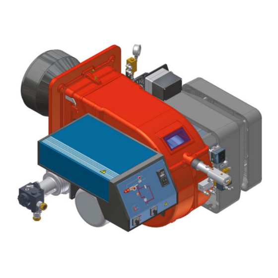
- Page 1 RG91 - RG92 - RG93 RG510 - RG515 RG520 - RG525 Progressive - Fully modulating Light oil burners MANUAL OF INSTALLATION - USE - MAINTENANCE BURNERS - BRUCIATORI - BRULERS - BRENNER - QUEMADORES - ГОРЕЛКИ M039214CC Rel. 2. 11/2010...
-
Page 2: Table Of Contents
TABLE OF CONTENTS WARNINGS ................................3 PART I: INSTALLATION ............................5 GENERAL FEATURES ................................... 5 How to interpret the burner’s “Performance curve” ......................... 6 Technical specifications .................................. 7 Performance curves ..................................8 Overall dimensions ..................................9 MOUNTINGS AND CONNECTIONS ............................11 Packing ...................................... -
Page 3: Warnings
WARNINGS THIS MANUAL IS SUPPLIED AS AN INTEGRAL AND ESSENTIAL PART OF THE PRODUCT AND MUST BE DELIVERED TO THE USER. INFORMATION INCLUDED IN THIS SECTION ARE DEDICATED BOTH TO THE USER AND TO PERSONNEL FOLLOWING PRO- DUCT INSTALLATION AND MAINTENANCE. THE USER WILL FIND FURTHER INFORMATION ABOUT OPERATING AND USE RESTRICTIONS, IN THE SECOND SECTION OF THIS MANUAL. - Page 4 DIRECTIVES AND STANDARDS 3b) FIRING WITH GAS, LIGHT OIL OR OTHER FUELS Gas burners GENERAL European directives: The burner shall be installed by qualified personnel and in com- - Directive 2009/142/EC - Gas Appliances; pliance with regulations and provisions in force; wrong installation Directive 2006/95/EC on low voltage;...
-
Page 5: Part I: Installation
PART I: INSTALLATION GENERAL FEATURES The burners of this series represent monoblock burners made in die-cast aluminium housing with relative flange to work on heating generators. The maximum output range is from 2100kW to 8000kW (according to the model).They can be provided in progressive or fully-modulating version. -
Page 6: How To Interpret The Burner's "Performance Curve
Burners are identified by burner type and model. Burner model identification is described as follows. * *. Type RG520 Model RG91 - RG92 - RG93 - RG510 - RG515 - RG520 - RG525 (1) BURNER TYPE G - Light oil (2) FUEL... -
Page 7: Technical Specifications
Operating temperature °C -10 ÷ +50 Storage temperature °C -20 ÷ +60 Working service * Intermittent BURNERS RG510 RG515 RG520 RG525 Output min. -max. kW 1314 - 3953 1628 - 4884 2326 - 6977 2000 - 8000 Fuel Light oil Light oil rate min. -
Page 8: Performance Curves
RG91 RG92 1200 1600 2000 2400 2800 1200 1600 2000 2400 RG93 500 1000 1500 2000 2500 3000 3500 4000 4500 RG510 RG515 1000 1800 2600 3400 4200 1200 2000 2800 3600 4400 5200 RG525 RG520 2000 2800 3600 4400 5200 6000 6800 7600... -
Page 9: Overall Dimensions
Overall dimensions (mm) boiler recommended dril- ling template burner flange Omin Omax (AS) (AL) (BS) (BL) RG91 1345 1518 1045 RG92 1339 1512 1045 RG93 1339 1512 1045 *AS/BS: measure referred to burner with standard blast tube provided *AL/BL: measure referred to burner with extended blast tube provided... - Page 10 1671 219 217 246 35 468 1141 571 1313 642 329 369 540 496 M14 552 390 390 766 328 270 RG515 1451 1671 219 217 246 35 508 1141 571 1323 642 350 390 540 496 M14 552 390 390...
-
Page 11: Mountings And Connections
MOUNTINGS AND CONNECTIONS Packing The burners are dispatched in wooden packages whose dimensions are: series 9x: 1720 mm x 1270 mm x 1020 mm (L x P x H) series 5xx: 1800 mm x 1500 mm x 1300 mm (L x P x H) Packing cases of this kind are affected by humidity and are not suitable for stacking. -
Page 12: Handling The Burner
Handling the burner ATTENTION! The lhandling operations must be carried out by specialised and trained personnel. If these opera- tions are not carried out correctly, the residual risk for the burner to overturn and fall down still persists. To move the burner, use means suitable to support its weight (see paragraph “Technical specifications”). The unpacked burner must be lifted and moved only by means of a fork lift truck. -
Page 13: Installation Diagram Of Light Oil Pipes
Fig. 5 - Suction circuit Manual valve Light oil filter Light oil feeding pump One way valve Flexible hoses Relief valve NOTE: in plants where gravity or ring feed systems are provided, install an automatic interception device (see n. 4 - Fig. 6). Installation diagram of light oil pipes PLEASE READ CAREFULLY THE “WARNINGS”... -
Page 14: About The Use Of Fuel Pumps
Suntec TA Pumps To change from a 1-pipe system to a 2-pipe-system, insert the by-pass plug G (as for ccw-rotation- referring to the pump shaft). Caution: Changing the direction of rotation, all connections on top and side are reversed. ... -
Page 15: Light Oil Pumps
Light oil pumps The pumps provided with these burners are Suntec TA (except mod. RG525). RG525: Suntec T pump and Suntec TV pressure governor are provided. Suntec TA.. Oil viscosity 3 ÷ 75 cSt Oil temperature 0 ÷ 150°C Min. suction pressure - 0.45 bar to avoid gasing Max. -
Page 16: Assembling The Light Oil Flexible Hoses
Assembling the light oil flexible hoses To connect the flexible light oil hoses to the pump, proceed as follows, according to the pump provided: remove the closing nuts A and R on the inlet and return connections of the pump; screw the rotating nut of the two flexible hoses on the pump being careful to avoid exchanging the inlet and return lines: see the arrows marked on the pump that show the inlet and the return (see prevoius paragraph). -
Page 17: Oil Circuit
Oil circuit The fuel is pushed into the pump 1 to the nozzle 3 at the delivery pressure set by the pressure governor. The solenoid valve 2 stops the fuel immission into the combustion chamber. The fuel flow rate that is not burnt goes back to the tank through the return circuit. The spill-back nozzle is feeded at constant pressure, while the return line pressure is adjusted by means of the pressure governor controlled by an actuator coupled to an adjusting cam. - Page 18 RG525 Oil circuit The fuel is pushed into the pump 1 to the nozzle 3 at the delivery pressure set by the pressure governor. The solenoid valve 2 stops the fuel immission into the combustion chamber. The fuel flow rate that is not burnt goes back to the tank through the return circuit. The spill-back nozzle is feeded at constant pressure, while the return line pressure is adjusted by means of the pressure governor controlled by an actuator coupled to an adjusting cam.
-
Page 19: Electrical Connections Diagram
Electrical connections diagram RESPECT THE BASIC SAFETY RULES. MAKE SURE OF THE CONNECTION TO THE EARTHING SYSTEM. DO NOT REVERSE THE PHASE AND NEUTRAL CONNECTIONS. FIT A DIFFERENTIAL THERMAL MAGNET SWITCH ADE- QUATE FOR CONNECTION TO THE MAINS. STRICTLY OBSERVE THE DATA PLATE. ... -
Page 20: Adjusting Air And Light Oil Flow Rate
RETURN PRESSURE (bar) BERGONZO A3 11 - 13 5 (recommended)) FLUIDICS WR2/UNIGAS M3 7 (recommended) 19 - 20 Example: as far as over 100kg/h nozzle the 80% of the nozzle rated flow rate is achieved with 18bar return pressure (see Fig. 20). - Page 21 Fig. 21...
-
Page 22: Adjustments - Brief Description
ATTENTION: before starting the burner up, be sure that the manual cutoff valves are open. Be sure that the mains switch is closed. Before starting up the burner, make sure that the return pipe to the tank is not obstructed. Any obstruction would cause the pump seal to break. - Page 23 ;start the burner up by means of the thermostat series and wait until the pre-purge time comes to an end; drive the burner to high flame stage, by means fo the thermostat TAB (as far as fully-modulating burners, see the related para- graph).
- Page 24 the rod TR towards the air damper shaft, the air damper opens and consequently the air flow rate increases, moving it far from the shaft the air damper closes and the air flow rate decreases. Note: once the procedure is perfomed, be sure that the blocking nut RA is fasten. Do not change the position of the air damper rods.
-
Page 25: Adjustment By The Siemens Sql33.. Actuator
Adjustment by the Siemens SQL33.. actuator Check the fan motor rotation (see page 19). owith the electrical panel open, prime the oil pump acting directly on the related CP contactor (see next picture): check the pump motor rotation and keep pressing for some seconds until the oil circuit is charged; bleed the air from the M pressure gauge port (Fig. - Page 26 manually drive the adjusting cam SV to the high flame position and set the actuator to the AUTO mode (by the related switch - see picture) to lock the adjusting cam. 10 the nozzle supply pressureis already factory-set and must not be changed. Only if necessary, adjust the supply pressure as fol- lows (see related paragraph);insert a pressure gauge into the port shown on Fig.
- Page 27 sting cam as to reach the minimum output point: gradually move the adjusting cam in order to adjust each of the V screws as to describe the cam foil shape. 15 to change the SV position set the actuator on the manual mode (MAN), turn the adjusting cam SV and set again the actuator to the AUTO mode to lock the adjusting cam;...
-
Page 28: Fully Modulating Burners
Fully modulating burners To adjust the fully-modulating burners, use the CMF switch on the burner control panel (see next picture), instead of the TAB thermo- stat as described on the previous paragraphs about the progressive burners. Go on adjusting the burner as described before, paying attention to use the CMF switch intead of TAB. -
Page 29: Part Ii: Operation
PART II: OPERATION LIMITATIONS OF USE THE BURNER IS AN APPLIANCE DESIGNED AND CONSTRUCTED TO OPERATE ONLY AFTER BEING CORRECTLY CONNEC- TED TO A HEAT GENERATOR (E.G. BOILER, HOT AIR GENERATOR, FURNACE, ETC.), ANY OTHER USE IS TO BE CONSIDE- RED IMPROPER AND THEREFORE DANGEROUS. -
Page 30: Operation
OPERATION ATTENTION: before starting the burner up, be sure that the manual cutoff valves are open. Be sure that the mains switch is closed. Set to the ON position the switch A on the control panel of the burner. Check the control box is not in the lockout position (light B must be off); in such a case reset it by the reset pushbutton C. Check that the series of thermostats (or pressure switches) enables the burner to operate. -
Page 31: Part Iii: Maintenance
PART III: MAINTENANCE At least once a year carry out the maintenance operations listed below. In the case of seasonal servicing, it is recommended to carry out the maintenance at the end of each heating season; in the case of continuous operation the maintenance is carried out every 6 months. -
Page 32: Removing The Combustion Head
Removing the combustion head Remove the top cover C; remove the photoresistor from its seat; unscrew the revolving connectors (E in figure) on the fuel pipes (use 2 spanners to avoid loosening the connections attached to the distributor block); loosen VRT screw to free the threaded rod AR, then screw out the 2 screws V holding the washer R and the screw VRT again; remove the whole assembly as shown in figure;... -
Page 33: Correct Position Of Electrodes And Combustion Head
Correct position of electrodes and combustion head ATTENTION: avoid the ignition electrodes to get in touch with metallic parts (blast tube, head, etc.), otherwise the boiler’s operation would be compromised. Check the electrodes position after any intervention on the combustion head. To guarantee a good ignition the measures (in mm) shown on the next pictures must be observed. -
Page 34: Seasonal Stop
Checking the detection current To measure the detection signal follow the diagram in Fig. 30. If the signal is not in the advised range, check the electrical contacts, the cleaning of the combustion head, the position of the photoresistor and if necessary replace it. series 9x: LMO MC TERMINAL BLOCK series 5xx: LAL25... -
Page 35: Troubleshooting
TROUBLESHOOTING MAIN SWITCH OPEN LINE FUSE INTERVENTION MAX. PRESSURE SWITCH FAULT FAN THERMAL CUTOUT INTERVENTION AUXILIARY RELAIS FUSES INTERVENTION CONTROL BOX FAULT SERVOCONTROL FAULT SMOKEY FLAME ... -
Page 36: Spare Parts
BURNER MODULATOR 2590118 2590119 2590120 PUMP mod. SUNTEC 2610202 2610202 NOZZLE mod. BERGONZO A3 2610203 NOZZLE mod. FLUIDICS WR2 50° 2610230 NOZZLE mod. UNIGAS M3 45° 2700217 2700217 27002xx OIL GUN (standard) 2700223 2700223 27002xx OIL GUN (extended) 3060160 3060161... - Page 37 2590121 2590121 2590124 PUMP mod. SUNTEC 2610203 2610203 2610203 2610203 NOZZLE mod. FLUIDICS WR2 2610230 2610230 2610230 2610230 NOZZLE mod. UNIGAS M3 45° 2700225 2700225 2700253 2700253 OIL GUN (standard) 2700224 2700224 2700254 2700255 OIL GUN (long) 3060163 3060164 3060165...
-
Page 38: Burner Exploded View
BURNER EXPLODED VIEWД ITEM DESCRIPTION ITEM DESCRIPTION ITEM DESCRIPTION FLANGE STANDARD BLAST TUBE 14.2 OIL MANIFOLD AIR INLET CONE AIR DAMPER INDEX 14.3 CONNECTOR CLOSING PLATE 12.1 15.1 LONG IGNITION ELECTRODE INDEX LABEL 12.2 MOTOR 15.2 OIL GUN HOLDER RING NUT 12.3 COUPLING 15.3... -
Page 40: Electrical Wiring Diagrams
Wiring diagram 07-479 - Burners fully modulating - RG91 - RG92 - RG93 Wiring diagram 11-272 - Burners progressive - RG510 - RG515 - RG520 Wiring diagram 11-293 - Burners fully modulating - RG510 - RG515 - RG520 Wiring diagram 11- 344 - Burners progressive - RG525... -
Page 41: Appendix
APPENDIX The multicolour «LED» is the key indicating element for both visual diagnosis and interface diagnosis. SIEMENS OIL BURNERS AUTOMATIC CONTROLLER SIEMENS LMO14 - LMO24 - LMO44 The LMO... burner controls are designed for the start-up and supervision of single- or 2-stage forced draught oil burners in intermittent operation. Yellow Yellow-burning flames are supervised with photoresistive detectors QRB..., blue-burning flames with blue-flame detectors QRC... - Page 42 LMO14 LMO24 - LMO44 A ´ μC control μC1 μC2 t 3n t 3n t 3n 7130a01e/0700 LMO24 - LMO44 7130d03e/ 0700 µC cont r ol µC 1 µC 2 Alarm device kbr... Cable link (required only when no oil pre-heater is used) BV...
- Page 43 6 in the bottom of the base General unit data 6 lateral threaded knockout holes for cable entry glands Pg11 or M20 Mains voltage AC 230 V +10 % / -15 % Operation AC 120 V +10 % / -15 % Mains frequency 50...60 Hz ±6 % Flame detector and flame simulation test are made automatically during...
- Page 44 t3’ Long preignition time: «Z» connected to terminal 15. Postignition time: Lockout indication - «Z» must be connected to terminal 15 - With short preignition, «Z» remains on until «TSA» has elapsed connec- tion to terminal 16. Interval «BV1 – BV2» or «BV1 - LR»: On completion of «t4», vol- tage is present at terminal 19.
- Page 45 Sequence diagram Control output at terminal t3 n t3" t1 6 V II V III X II t10* X III X IV Lockout position indication Prepurge time with air damper fully open Safety time Preignition time, short («Z» connected to terminal 16) T3’...
- Page 48 C.I.B. UNIGAS S.p.A. Via L.Galvani, 9 - 35011 Campodarsego (PD) - ITALY Tel. +39 049 9200944 - Fax +39 049 9200945/9201269 web site: www.cibunigas.it - e-mail: cibunigas@cibunigas.it Note: Specifications and and data subject to change. Errors and omissions excepted.
Need help?
Do you have a question about the RG515 and is the answer not in the manual?
Questions and answers