Table of Contents
Advertisement
Quick Links
Advertisement
Table of Contents

Related Manuals for ESAB MIGMATIC 250


Summary of Contents for ESAB MIGMATIC 250
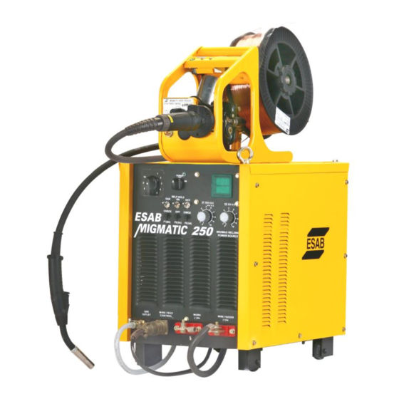
- Page 1 MIGMATIC 250 MIG/MAG Power Source Instruction manual...
- Page 2 MIGMATIC 250 Instruction manual Installation, Operation & General maintenance...
-
Page 3: Table Of Contents
C O N T E N T S Item Page No. SAFETY MIGMATIC 250 POWER SOURCE Assembling Accessories List Rating Cautions for Installation Items for Installation Front Panel Welding Operation Maintenance & Inspection After Sales Service Fault Finding MIGMATIC WIRE FEEDER... -
Page 4: Safety
SAFETY Users of ESAB welding equipment have the ultimate responsibility for ensuring that anyone who works on or near the equipment observes all the relevant safety precautions. Safety precautions must meet the requirements that apply to this type of welding equipment. - Page 5 Read and understand the instruction manual before installing or operating. ESAB can provide you with all necessary welding protection and accessories. WARNING Arc welding and cutting can be injurious to yourself and others. Take precautions when welding. Ask for your employer’s safety practices which should be based on manufacturers’...
-
Page 6: Migmatic 250 Power Source
MIGMATIC WIRE FEEDER with accessories Welding Torch PSF 250 Regulator cum Flowmeter or Regulator with Flowmeter Heater Core ACCESSORIES LIST FOR MIGMATIC 250 MIG/MAG WELDING POWER SOURCES Fuse, element 3A 2 piece Fuse, element 8A 1 piece Instruction Manual 1 piece... -
Page 7: Cautions For Installation
CAUTIONS FOR INSTALLATION Capacity of Equipment Input Voltage 415 VAC ±10 % Number of Phase & Frequency 3 phase, 50 Hz Maximum rating of Equipment 9.5 KVA Capacity of Fuse (B Class) 16 Amps HRC Output Cable More than 38 mm •... -
Page 8: Items For Installation
ITEMS FOR INSTALLATION Item MIGMATIC 250 Welding Power Source Wire feeder (Migmatic) Welding Torch PSF 250 Base Metal Gas Regulator Gas cylinder Switch Box Return Cable with Earth Clamp Inlet Gas Hose from Gas cylinder to Welding Machine Heater with cable for connection to socket on Machine... - Page 9 List of Items Item No. Description / Code Power ON Lamp / 1651685051 Power ON-OFF Selector Switch / 1651685115 Voltage Selector Switch. / 0466401001 Gas Check Switch / 1651685177 Self-Hold ON/ OFF Selector Switch / 1651685116 OCV Check Switch / 1651685177 Gas Outlet to Welding Torch / Socket for Wirefeeder Control cable connection / Output Power Terminals / 1651685125...
-
Page 10: Front Panel
WELDING OPERATION The welding operation can be adjusted from the front panel of the power source. 1. The ON/OFF switch on the front panel switches on the Power Source. This will cause the light emitting diode on the front panel to light up. Cooling fan will start rotating. - Page 11 • The weld lies on top of the material and does not flow out. Remedy: Increase the setting of the voltage selector switch to a higher value. • Holes are burnt in the material. Welding current too high. Remedy: Reduce the current. •...
- Page 12 Switch on the potentiometer (t1) and then set for welding time (graded 1- 10). Switch on the potentiometer (t2) and then set it for interval duration (off time) (graded 1-10) Both welding time and interval duration can be set Steplessly between 0.2 and 2 sec. Welding voltage and current are set as described earlier.
-
Page 13: Maintenance & Inspection
MAITENANCE & INSPECTION The maintenance and inspection should be carried out only after the switches in the switch box are certainly turned OFF. Try to maintain and inspect the set regularly as per the following guidelines. Regular Inspection Every 3-6 months, depending on operation frequency: Inspection Portion Inspection Point Maintenance Method... -
Page 14: After Sales Service
In case of any abnormality observed during usage of the equipment, which could not be rectified at site, please contact immediately Area Sales Manager of the nearest unit of ESAB INDIA LIMITED with the following details: Serial number of the equipment & type Nature of the complaint with the relevant details, if possible and the details of Input Supply. -
Page 15: Fault Finding
FAULT FINDIG Fault Cause Corrective Action On switching on the Power Fuse F3(3A) has Opened. Check and replace fuse Source the fan does not rotate Fault In AC Input supply Check the three phase AC supply. Power LED does not glow on Fuse (8A) has blown Check &... -
Page 16: Rating
MM 250 WIREFEEDER UNIT RATING Parameter Value Applicable wire diameter 0.8 mm to 1.2 mm Wire feed motor 18V, D.C. Max Applicable wire spool Shaft Dia 50 mm Outer Dia 280 mm or less Width 105 mm or less Length of cable and hose 5 Mts Weight (Without Inter-Connection) 6 Kgs... - Page 17 Wire Setting Wire Inching Turn Power Source ON Loosen the spool locknut-1 Press Inch Button-4 Wire Feeder Place the Wire Spool-2 Release inch button when wire comes out Lock with the Nut 1-2 cm from Torch tip Lift the Pressure Arm-3 Insert wire 2-3 cm in SUS Tube...
-
Page 18: Maintenance
MOTOR AND FEEDROLL BLOCK ASSEMBLY MOTOR PRESSURE ADJUSTMENT KNOB PRESSURE FEED ROLLER MAINTENANCE • SUS Tube: Wipe of dust or dirt once a week • Feed Roller: If the groove is badly deformed or worn out, change the roller V-groove as per the diameter of the wire used. -
Page 19: Wiring Diagram
WIRING DIAGRAM... -
Page 20: Spares List For Power Source And Wire Feeder
SPARES LIST FOR MIGMATIC 250 POWER SOURCE ITEM CODE DESCRIPTION SPARES HOLDING FOR 6 AND ABOVE 1651686015 CRATER PCB MIG-250 0466401001 VOLTAGE SELECTOR SWITCH 1611642018 FUSE ELEMENT 3A 1611642301 DIGITAL V/A METER 1651684041 COOLING FAN 1651685051 POWER ON LED LAMP (GREEN) -
Page 21: Rated Specification And Accessories
WELDING TORCH PSF 250 RATED SPECIFICATIONS: MODEL PSF 250 ORDERING CODE: 4650692900- PSF 250 3 M 4650692901- PSF 250 4.5 M Permitted Welding 250A Current at 60 % Duty Mixed Gas, Argon (Al) 225A cycle Cooling system Self cooled Torch shape Curved type with 360 degree swiveling facility Recommended Gas Flow 8-13 litres / min. - Page 22 • Replacing the Wire Liner: 1. Fit the correct nipple 2. Remove Gas Nozzle and Tip Adaptor 3. Fit the wire liner in the hose package 4. Cut the wire guide to the correct length. During cutting, the welding torch must be extended with the wire guide fully inserted into the rear connector.
-
Page 23: Maintenance
• The gas nozzle and front parts of torch must be kept free of weld spatter. Spray anti-spatter agent at an angle into the gas nozzle from two directions. Use ESAB Anti spatter agent to prevent spatter sticking. • The contact tip has to be replaced when the hole has become more than twice... -
Page 24: List Of Consumables & Accessories
CONSUMABLE ACCESSORIES APPLICABLE FOR THE TORCH DESCRIPTION SPARES CODE HOLDING TIPCU-CR-ZR 0.8 (M6) 1651691921 1.0 (M6) 1651691909 1.2 (M6) 1651691911 1.6 (M6) 1651691630 1.6 (M8) 1651691910 TIPCU Std 1651691923 0.8 (M6) 1.0 (M6) 1651691924 1.2 (M6) 1651691904 1.2 (M8) 1651691928 Plastic Nut for swan neck 1651691050 Swan neck... -
Page 25: Weld Defects, Possible Causes & Corrective Actions
GAS METAL ARC WELDING Welding Defects, Possible Causes And Corrective Actions This welding process produces high quality welds when proper welding procedures are used. The absence of flux of electrode covering eliminates slag inclusions in the weld. Some dross formation may occur when highly deoxidized steel electrodes are used, and it should be removed before the next weld bead or pass is made. - Page 26 Possible causes Corrective actions Lack of penetration Improper point preparation Joint design must be adequate to provide access to the bottom of the grove while maintaining proper nozzle-to-work distance and arc characteristics. Reduce root face height. Provide or Increase the root opening in butt joints.
- Page 27 Possible causes Corrective actions Excessive melt-through Excessive heat input Reduce the electrode feed rate and arc voltage. Increase the travel speed. Reduce excessive root opening. Increase root face height. Incomplete fusion A. Weld zone surfaces not free of film Clean all groove faces and weld zone or scale surfaces of any mill scale or impurities prior to welding.
- Page 28 Web: www.esabindia.com...
Need help?
Do you have a question about the MIGMATIC 250 and is the answer not in the manual?
Questions and answers