Table of Contents
Advertisement
Quick Links
Instruction Manual
D104742X012
Fisher
easy-Drive
™
Contents
. . . . . . . . . . . . . . . . . . . . . . . . . . . . . . . . .
. . . . . . . . . . . . . . . . . . . . . . . . . . . . .
. . . . . . . . . . . . . . . . . . . . . . . . . . . . . . . . .
. . . . . . . . . . . . . . . . . . . . . . . . . . . . . . .
. . . . . . . . . . . . . . . . . . . . . . . . . . . . . . . . . . . . .
. . . . . . . . . . . . . . . . . . . . . . . . . . . . . . . . . .
. . . . . . . . . . . . . . . . . . . . . . . . . .
. . . . . . . . . . . . . . . . . . . . . . . . . . . . . .
. . . . . . . . . . . . . . . . . . . . . . . . . . . . .
. . . . . . . . . . . . . . . . . . . . . . . . . . . .
. . . . . . . . . . . . . . . . . . . . . . . . . . . . .
. . . . . . . . . . . . . . . . . . . . . . . . . . . . . . . .
. . . . . . . . . . . . . . . . . . . . . . . . . . . . . . . .
. . . . . . . . . . . . . . . . . . . . . . . . . . . . . . .
. . . . . . . . . . . . . . . . . . . . . . . . . . . . . . . . . . .
. . . . . . . . . . . . . . . . . . . . . . . . . . . . . . . . . . .
. . . . . . . . . . . . . . . . . . . . . . . . .
. . . . . . . . . . . . . . . . . . . . . . . . .
Introduction
Scope of Manual
This instruction manual provides installation, maintenance, and parts information for the easy-Drive
200R. Do not install, operate, or maintain an easy-Drive 200R without being fully trained and qualified in
valve, actuator, and accessory installation, operation, and maintenance. To avoid personal injury or
property damage, it is important to carefully read, understand, and follow all the contents of this
manual, including all safety cautions and warnings. If you have any questions about these instructions,
contact your
Description
The easy-Drive 200R electric rotary actuators are used on rotary-shaft valve bodies for throttling or on-off applications.
The 200R has an ISO 5211 mating interface that allows installation to non-Fisher valves. Style F mounting is available
for coupling with Fisher rotary valves. This actuator is ideal for use on pressure and flow control applications for Fisher
Vee-Ball NPS 1-6, HPBV NPS 2-4 and non-Fisher 90° rotary valves with 9 mm, 11 mm, 14 mm, or 19 mm square shaft
connections, and 5/8-inch or 3/4-inch splined shaft connections. In applications that require a known loss of power
position, an RPU-100 can be used to drive the easy-Drive actuator open or
Instruction Manual (D104551X012).
www.Fisher.com
™
. . . . . . . . . . . . . . . . . . . . . . . . .
. . . . . . . . . . . . . . . . . . . . .
. . . . . . . . . . . .
. . . . . . . . . . . . . . . .
. . . . . . . . . . . . . . . . . .
. . . . . . . . . . . . . . . . . .
. . . . . . . . .
Emerson sales office
200R
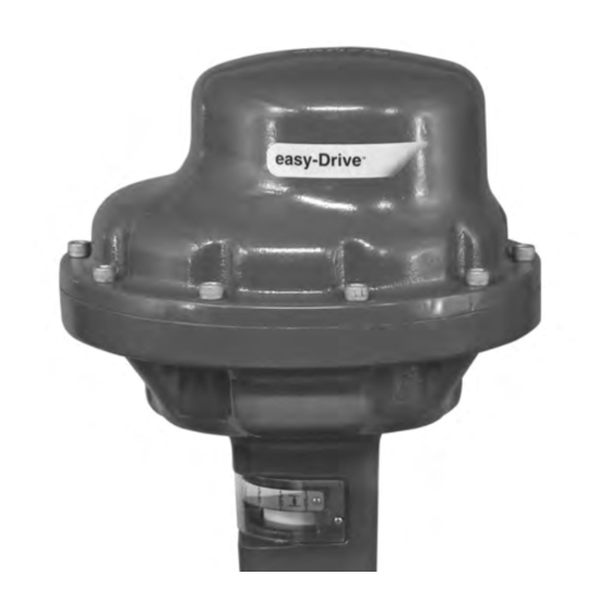
Figure 1. Fisher easy-Drive 200R
1
1
1
3
3
3
4
5
5
11
11
11
12
13
13
17
17
18
X1913
19
22
22
22
26
27
32
before proceeding.
closed.
Consult the easy-Drive RPU-100
easy-Drive 200R
November 2023
Advertisement
Table of Contents

Related Manuals for Emerson Fisher easy-Drive 200R


Summary of Contents for Emerson Fisher easy-Drive 200R
-
Page 1: Table Of Contents
™ Contents Figure 1. Fisher easy-Drive 200R Introduction ....... . . - Page 2 Instruction Manual easy-Drive 200R November 2023 D104742X012 Table 1. Specifications Material Temperature Capabilities Torque Electric Actuator Assembly: Rated: 124 N•m (1100 in•lbf) -40 to 70°C (-40 to 158°F) Nominal Stroke Speed Available Actuator Configurations 9° per second at 24 VDC Positioning Hazardous Area Approvals Compatible Fisher Valve Types and Sizes...
-
Page 3: Specifications
Table 1 lists specifications for the easy-Drive 200R. Some of the specifications for a given actuator as it originally comes from the factory are stamped on a nameplate located on the lower actuator enclosure. Educational Services Emerson Educational Services Phone: 1-800-338-8158 E-mail: education@emerson.com emerson.com/mytraining... -
Page 4: Installation
Instruction Manual easy-Drive 200R November 2023 D104742X012 Installation WARNING Always wear protective gloves, clothing, and eyewear when performing any installation operations to avoid personal injury. To avoid personal injury or property damage caused by bursting of pressure‐retaining parts or by uncontrolled process fluid, be certain the service conditions do not exceed the limits shown on the valve nameplate and in table 1. -
Page 5: Special Instructions For "Safe Use" And Installations In Hazardous Locations
Instruction Manual easy-Drive 200R D104742X012 November 2023 Special Instructions for “Safe Use” and Installations in Hazardous Locations WARNING To avoid static discharge from the enclosure, do not rub or clean the enclosure with solvents. To do so could result in an explosion. - Page 6 7. Externally adjustable travel stops are used to limit the degree of rotation at both ends of the actuator stroke to calibrate valve to the actuator. 8. Calibrate the actuator. See Calibration Instructions section of this manual. Figure 2. Fisher easy-Drive 200R CONTROLLER POWER AND...
- Page 7 Instruction Manual easy-Drive 200R D104742X012 November 2023 Figure 3. Fisher easy-Drive 200R Wiring Diagram FIELD WIRING CONNECTIONS POWER AND CONTROL TERMINAL GE47302-7 TOP VIEW CONTROLLER Power Requirements Ensure a stable DC power source is available, maintaining less than 5% ripple and sufficiently surge protected for the application.
- Page 8 Instruction Manual easy-Drive 200R November 2023 D104742X012 Figure 4. Wiring - Analog Input Figure 5. Wiring - Dual Dry Contact...
- Page 9 Instruction Manual easy-Drive 200R D104742X012 November 2023 Figure 6. Wiring - Single Dry Contact Figure 7. Wiring - Modbus Input...
- Page 10 Instruction Manual easy-Drive 200R November 2023 D104742X012 Figure 8. Wiring - Auxiliary Digital I/O set to input (40080=0) Figure 9. Wiring - Auxiliary Digital I/O set to output 10 V, 25 mA max...
-
Page 11: Configuration
All configuration within the actuator is done by setting values in Modbus registers. Configuration software, providing a visual interface to the registers, is available through your Emerson sales office or at www.emerson.com/en-us/catalog/fisher-easy-drive. Control and monitoring can be done using any Modbus master (flow computer, PLC, PC). -
Page 12: Connecting Using The Fisher Easy-Drive Configuration Software
Instruction Manual easy-Drive 200R November 2023 D104742X012 Connecting using the Fisher easyDrive configuration software The Fisher easyDrive Configurator software allows configuration and diagnosing of the Fisher easyDrive electric actuator with a graphical interface. Connect a PC to the actuator using a serial or USB to RS-485 device using the wiring instructions above. -
Page 13: Initial Setup
Instruction Manual easy-Drive 200R D104742X012 November 2023 Initial Setup The control method selection determines the control signal to which the valve will respond. Only the control signal selected will result in movement of the valve; all others will be ignored. D Control Methods H Dual Contact On/Off H Dual Contact Stepped Control... - Page 14 Instruction Manual easy-Drive 200R November 2023 D104742X012 Span Calibration It will be necessary to perform a span calibration. A span calibration is accomplished by the following method: Note If the actuator is equipped with a RPU-100, the RPU-100 must be disabled via the Disable switch prior to powering off the actuator. 1.
- Page 15 Instruction Manual easy-Drive 200R D104742X012 November 2023 5. For On/Off operation using dualinput dry contact: a. Close the contact to create a short between pins COMMON and CLOSE. If Span is currently uncalibrated, valve ball/disk will not move at this time. b.
- Page 16 Instruction Manual easy-Drive 200R November 2023 D104742X012 5. Set the 4-20 mA signal to the desired value for when the valve is to be open. 6. Enter this value into the Commanded mA Signal text box and press Next. Figure 15. Fisher easy-Drive Configuration Software 7.
-
Page 17: Operational Verification
Instruction Manual easy-Drive 200R D104742X012 November 2023 Operational Verification WARNING To avoid personal injury or property damage, be aware that the valve will move and respond to an input signal during start 1. Before turning on power to the unit, be sure that a closed signal is being commanded to the unit. D Single DryContact: contact is open. -
Page 18: Maintenance
Instruction Manual easy-Drive 200R November 2023 D104742X012 2. Unit does not respond to 420 mA signal a. Green heartbeat LED will pulse near Modbus terminals when power is present. Verify the 12VDC to 24VDC is present on the power terminals as shown on the cover. b. -
Page 19: Disassembly
Instruction Manual easy-Drive 200R D104742X012 November 2023 WARNING Avoid personal injury from sudden release of process pressure or bursting of parts. Before performing any maintenance operations: D Do not remove the actuator from the valve while the valve is still pressurized. D Always wear protective gloves, clothing, and eyewear when performing any maintenance operations to avoid personal injury. - Page 20 Instruction Manual easy-Drive 200R November 2023 D104742X012 2. Remove any positioning licenses to a license dongle if you wish to use them on a different device. 3. Perform a Restore to Defaults operation on the control board if the control board is to be used on a different actuator.
- Page 21 Instruction Manual easy-Drive 200R D104742X012 November 2023 Figure 18. Fisher easy-Drive 200R Actuator Dimensions 320.1 12.60 393.6 15.50 inch GE69539...
-
Page 22: Parts Ordering
WARNING Use only genuine Fisher replacement parts. Components that are not supplied by Emerson should not, under any circumstances, be used in any Fisher actuator, because they may void your warranty, might adversely affect the performance of the actuator, and could cause personal injury and property damage. - Page 23 Instruction Manual easy-Drive 200R D104742X012 November 2023 Figure 19. Fisher easy-Drive 200R Exploded View GE69539_3...
- Page 24 Instruction Manual easy-Drive 200R November 2023 D104742X012 Figure 20. Fisher easy-Drive 200R Actuator Exploded View GE69539...
- Page 25 Instruction Manual easy-Drive 200R D104742X012 November 2023 Figure 21. Fisher easy-Drive 200R Mounting Positions VALVE INLET LEFT HAND MOUNTING VALVE INLET RIGHT HAND MOUNTING POSITION 1 POSITION 3 POSITION 4 POSITION 2 (PREFERRED) CONDUIT CONDUIT CONDUIT CONDUIT FLOW FLOW FLOW...
-
Page 26: Actuator Mounting
Instruction Manual easy-Drive 200R November 2023 D104742X012 Actuator Mounting Configuration (Figure 21) Position 1 is preferred for both right or left hand mounted options. This has the conduit ports facing down below the centerline of the valve body, and the 210.1 mm (8.72 in) dimension of the actuator above the centerline of the valve, in either configuration. -
Page 27: Appendix A - Modbus
Instruction Manual easy-Drive 200R D104742X012 November 2023 Appendix A - Modbus A.1 Register Summary Table 5. easy-Drive 200R Modbus Map Type Name MB Register Default Values Notes Modbus command value with one implied decimal place (1000=100.0%). R/W at all times but only used in Modbus position command uint16 40001... - Page 28 Instruction Manual easy-Drive 200R November 2023 D104742X012 Table 3. easy-Drive 200L Modbus Map (cont.) Type Name MB Register Default Values Notes The time remaining in seconds at the current Dual Dual Contact Stepped uint16 40031 0-60001 Contact Stepped Position. If time is 60001, this Remaining Time position will be held until dual contact is closed.
- Page 29 Instruction Manual easy-Drive 200R D104742X012 November 2023 Table 3. easy-Drive 200L Modbus Map (cont.) Type Name MB Register Default Values Notes When the valve is in 4-20mA on/off mode, this value is Analog on/off open position uint16 40056 1-1000 the point at which the valve will open. It must be set to (100-10.0%) a larger value than the analog on/off close position.
- Page 30 Instruction Manual easy-Drive 200R November 2023 D104742X012 Table 3. easy-Drive 200L Modbus Map (cont.) Type Name MB Register Default Values Notes When dual contact is Open, the actuator will move to this position following position 1. It will remain at this position for the number of seconds specified in Dual uint16 Dual Contact Stepped Position 2 40084...
- Page 31 The actuator has experienced a fatal error and shut 0x1000 0001 0000 0000 0000 System or Watchdog fault 4096 down. Contact your Emerson sales office. The analog values entered do not match the Analog Input calibration value not in expected 0x0800 0000 1000 0000 0000 2048 analog signal level.
-
Page 32: Appendix B - Certificate Of Conformance
Instruction Manual easy-Drive 200R November 2023 D104742X012 Appendix B - Certificate of Conformance -continued-... - Page 33 Instruction Manual easy-Drive 200R D104742X012 November 2023 Appendix B - Certificate of Conformance (cont.)
- Page 34 Instruction Manual easy-Drive 200R November 2023 D104742X012...
- Page 35 Instruction Manual easy-Drive 200R D104742X012 November 2023...
- Page 36 Fisher and easy-Drive are marks owned by one of the companies in the Emerson business unit of Emerson Electric Co. Emerson and the Emerson logo are trademarks and service marks of Emerson Electric Co.
Need help?
Do you have a question about the Fisher easy-Drive 200R and is the answer not in the manual?
Questions and answers