Emerson Fisher 299H Series Instruction Manual
Pressure reducing regulators
Hide thumbs
Also See for Fisher 299H Series:
- Instruction manual (21 pages) ,
- Installation manual (9 pages) ,
- Manual (19 pages)
Advertisement
Instruction Manual
Form 5497
January 2014
299H Series Pressure Reducing Regulators
WARNING
!
Failure to follow these instructions or
to properly install and maintain this
equipment could result in an explosion
and/or fire causing property damage and
personal injury or death.
Fisher
regulators must be installed,
®
operated and maintained in accordance
with federal, state and local codes, rules
and regulations and Emerson Process
Management Regulator Technologies, Inc.
(Regulator Technologies) instructions.
If the regulator vents gas or a leak
develops in the system, service to the unit
may be required. Failure to correct trouble
could result in a hazardous condition.
Call a gas service person to service the
unit. Only a qualified person must install
or service the regulator.
Introduction
Scope of the Manual
This Instruction Manual provides installation, adjustment
and maintenance instructions and parts ordering
information for the 299H Series regulators. Complete
instructions and parts list for the 67C Series filtered pilot
supply regulator and other Fisher equipment are found
in separate instruction manuals.
Description
The 299H Series pressure reducing regulators provide
a broad capacity of controlled pressure ranges and
capacities in a wide variety of distribution, industrial
and commercial applications. A 299H Series regulator
has a pilot integrally mounted to the actuator casing.
The 299H Series regulators can handle inlet pressures
up to 175 psi / 12.1 bar depending on orifice size.
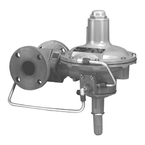
W7513
Figure 1. 299H Series Pressure Reducing Regulator
The integral token relief on the Types 299HR and
299HSR regulators is located in the pilot and opens
to relieve minor overpressure.
The Type 299HS provides overpressure or overpressure
and underpressure protection by completely shutting off
the flow of gas to the downstream system. It comes with
a Type VSX-2 slam-shut device which can be configured
for Ovepressure Shutoff (OPSO) or Overpressure and
Underpressure Shutoff (OPSO/UPSO). The slam-shut
device's actions are independent of the main valve and
of variations to the inlet pressure. The Type VSX-2
slam-shut device has internal or external registration.
External registration requires a downstream sensing line.
www.fisherregulators.com
299H Series
Advertisement
Table of Contents

Related Manuals for Emerson Fisher 299H Series


Summary of Contents for Emerson Fisher 299H Series
- Page 1 ® operated and maintained in accordance with federal, state and local codes, rules and regulations and Emerson Process Management Regulator Technologies, Inc. (Regulator Technologies) instructions. If the regulator vents gas or a leak develops in the system, service to the unit may be required.
-
Page 2: Specifications
299H Series Specifications Specifications for 299H Series constructions are given below. Some specifications for a given regulator as it originally comes from the factory are stamped on a nameplate located on the actuator upper casing. Available Constructions Minimum and Maximum Trip Pressure Ranges Type 299H: Pilot-operated pressure reducing See Table 3 regulator with a pilot integrally mounted to the... - Page 3 299H Series Table 2. Outlet Pressure Ranges TYPE PILOT CONTROL SPRING OUTLET (CONTROL) PRESSURE RANGE 299HR, Free Length Wire Diameter 299H 299HS and Part Number Color 299HSR Inch w.c. mbar Inch Inch 3.5 to 6 9 to 15 T13707T0012 Black 1.86 47.2 0.055...
-
Page 4: External Registration
299H Series OUTLET OUTLET 3/4 NPT DOWNSTREAM CONTROL LINE CONNECTION EXTERNAL REGISTRATION 3/4 NPT CONTROL LINE INLET CONNECTION 3/4 NPT PILOT SUPPLY CONTROL LINE SCREEN INLET CONNECTION PILOT SUPPLY SCREEN 3/4 NPT DOWNSTREAM CONTROL LINE INTERNAL CONNECTION REGISTRATION E0070 DUAL REGISTRATION INLET PRESSURE OUTLET PRESSURE ATMOSPHERIC PRESSURE... -
Page 5: Principle Of Operation
July 2008 July 2008 Type 299HS Type 299HS 299H Series OUTLET TION E0069 EXTERNAL REGISTRATION EXTERNAL REGISTRATION EXTERNAL REGISTRATION 3/4 NPT CONTROL LINE INLET CONNECTION PILOT SUPPLY SCREEN E0070 INTERNAL REGISTRATION INTERNAL REGISTRATION INTERNAL REGISTRATION TION INLET PRESSURE E0072 INLET PRESSURE OUTLET PRESSURE OUTLET PRESSURE INLET PRESSURE... -
Page 6: Overpressure Protection
299H Series Once the ball is released, the spring force on the stem This creates a higher pressure on the top side of the will push the stem and disk to the closed position main diaphragm (E) than on the bottom side, forcing against the seat shutting off all gas flow. - Page 7 299H Series if this regulator is overpressured or is within ratings does not preclude the possibility of installed where service conditions could damage from external sources or from debris in the exceed the limits for which the regulator lines. A regulator should be inspected for damage was designed or where conditions exceed periodically and after any overpressure condition.
- Page 8 299H Series In many instances, it will be necessary to enlarge the control line, block the body pitot tube with a screw downstream piping to keep flow velocities within good and gasket (keys 10 and 11, Figure 7). Remove the engineering practices.
-
Page 9: Maintenance
299H Series (key 36). Turning the adjusting screw clockwise into Use the following procedure to adjust the Underpressure the spring case increases the controlled or reduced Trip Spring: pressure setting. Turning the screw counterclockwise 1. Use the Type VSX adjusting tool to decreases the reduced pressure setting. - Page 10 299H Series 8. Loosely reassemble the diaphragm and diaphragm Note post parts so that the bolt holes in the diaphragm The regulator body may remain in the align with the corresponding holes in the lower pipeline during maintenance procedures. casing (key 1) when the lever (key 26) is fitted properly into the pusher post.
- Page 11 299H Series Main Body Valve Disk and Orifice Follow this procedure to inspect, clean or replace the main body valve disk or to inspect or replace the orifice. Part key numbers are referenced in Figures 5 and 6. Note The regulator body may remain in the pipeline during maintenance procedures.
-
Page 12: Parts Ordering
299H Series 11. When all maintenance is complete, refer to the 3. Remove the bonnet (key 34), spring seat (key 33) Startup section to put the regulator back into and control spring (key 32). operation and adjust the pressure setting. Tighten 4. -
Page 13: Parts List
299H Series T80391-6 T80391-6 TYPE 299H PILOT WITHOUT RELIEF VALVE TYPE 299HR PILOT WITH TOKEN RELIEF VALVE APPLY ANTI-SEIZE COMPOUND (L2) / ADHESIVE (A) Figure 4. 299H Series Pilot Assemblies Parts List Description Part Number O-ring, Nitrile (NBR) T12587T0012 299H Series Regulator (Figures 4, 5 and 6) Valve Stem Assembly 1L1426000A2 Valve Body... - Page 14 299H Series HEX NUTS APPLY CONSTANT HAND PRESSURE SPRING SEAT UPPER SPRING CASE CLOSING SPRING DIAPHRAGM POST LOCKING DOWN THE SPRING SEAT TO FACILITATE INSTALLING THE HEX NUTS T80391-2 EXTERNAL REGISTRATION T80391-3 INTERNAL REGISTRATION APPLY MULTI-PURPOSE LUBRICANT (L1) / MULTI-PURPOSE POLYTETRAFLUOROETHYLENE (PTFE) THREAD SEALANT (S1) Figure 5.
- Page 15 299H Series 3/4 NPT DOWNSTREAM CONTROL LINE CONNECTION T80391 T80391-4 T80391-7 DUAL REGISTRATION 299H SERIES PILOT TRIM APPLY MULTI-PURPOSE LUBRICANT (L1) / ANTI-SEIZE COMPOUND (L2) / THREAD LOCK SEALANT (S1) / ADHESIVE (A) Figure 5. 299H Series Interior Assembly (continued)
- Page 16 299H Series T80391-1 299H SERIES EXTERIOR VIEW TYPE 67CF PILOT TYPE 67CF PILOT SUPPLY REGULATOR SUPPLY REGULATOR T80391-5 T80391-5 TUBING AND FITTINGS WITH TUBING AND FITTINGS WITH OPTIONAL OPTIONAL TYPE P590 FILTER TYPE 67CF PILOT SUPPLY REGULATOR APPLY ANTI-SEIZE COMPOUND (L2) / MULTI-PURPOSE PTFE THREAD SEALANT (S1). Figure 6.
- Page 17 299H Series Parts List (continued) Description Part Number Diaphragm Head, Steel (2 required) T13812T0012 299H Series Regulator (Figures 4, 5 Insert (for Types 299HS and 299HSR only, and 6) (continued) see Figure 7) Aluminum T14013T0012 O-ring (for Types 299HS and 299HSR only, see Figure 7) Nitrile (NBR) T1072606562 Description...
- Page 18 299H Series VIEW A 10 11 VIEW A T80423 NOTE: FOR KEYS 12, 13, 17, 82 AND 83, REFER TO 299H SERIES REGULATORS PARTS LIST. Figure 7. Type VSX-2 Assembly (for Types 299HS and 299HSR)
- Page 19 299H Series USE THIS END FOR UNDERPRESSURE TRIP ADJUSTMENT USE THIS END FOR OVERPRESSURE TRIP ADJUSTMENT TYPE VSX ADJUSTING TOOL TYPE VSX TOOL BEING USED TO ADJUST A TYPE VSX-2 Figure 8. Type VSX Adjusting Tool...
- Page 20 For further information visit www.emersonprocess.com/regulators The Emerson logo is a trademark and service mark of Emerson Electric Co. All other marks are the property of their prospective owners. Fisher is a mark owned by Fisher Controls International LLC, a business of Emerson Process Management.
Need help?
Do you have a question about the Fisher 299H Series and is the answer not in the manual?
Questions and answers
do you have videos of operation of the 299H pressure reducing regulator, available on ur website? thank you.